Dual-Channel Power Meter ¸NRVD - Rohde & Schwarz
Dual-Channel Power Meter ¸NRVD - Rohde & Schwarz
Dual-Channel Power Meter ¸NRVD - Rohde & Schwarz

Create successful ePaper yourself
Turn your PDF publications into a flip-book with our unique Google optimized e-Paper software.
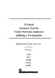
Thermal power sensors measure theaverage power irrespective of the signalshape and meet the highest demandson accuracy. Diode sensors are moresensitive – they are able to measurepower down to the pW range – but theirmeasurement accuracy is impaired whenhigh-level, non-sinusoidal signals are tobe measured. In the medium sensitivityrange, it is recommended to use diodesensors with integrated attenuator, e.g.the ¸NRV-Z2. This combination notonly allows considerably faster levelmeasurements in the range between10 µW and 100 µW than a thermalpower sensor; it also offers bettermatching than a highly sensitive diodedetector and still measures true rmspower.The peak envelope power of modulatedsignals can be measured by means of apeak power sensor of the ¸NRV‐Z3xseries. These sensors are suitablefor sync peak power measurementson TV transmitters and transmitterpower measurements on TDMA radioequipment or for general applications.Peak power sensors, which consist of afast diode detector followed by a peakholdcircuit, are calibrated individuallylike all <strong>Rohde</strong> & <strong>Schwarz</strong> power sensors.Besides the ¸NRV-Z power sensors,all ¸URV5-Z voltage probes can beused with the <strong>¸NRVD</strong>.Measurement accuracyThe accuracy of an RF powermeasurement essentially depends onthe characteristics of the sensor. Errorsencountered in this case are a functionof level, temperature and frequencyand cannot be eliminated completely bydesign.Error sources of power sensors:◆ Non-linearity◆ Level-dependent temperature effect◆ Frequency responseTo be able to measure correctly underany conditions, deviations from the idealmust be registered numerically andtaken into account in the measurementresult. The usual way to obtain accurateresults is to calibrate the sensors withthe aid of a generator prior to their use.The disadvantages of this method areobvious: a calibration has to be performedbefore each measurement, foreach individual sensor and even atintervals during a measurement (in thecase of temperature variations). For thisreason, <strong>Rohde</strong> & <strong>Schwarz</strong> has for yearsbeen producing sensors that offer greatconvenience to the user, although at ahigher expenditure on the part of themanufacturer. This technique can besummarized as:Plug in and goAll relevant parameters are measuredin the factory individually for eachsensor and then stored in the sensor.The level-dependent temperature effectis represented as a two-dimensionalcharacteristic with a great number ofmeasurement points.Each sensor comprises a temperaturesensor, the signal of which is evaluatedin the power meter at regular intervals.From the measured temperature andlevel values, the stored characteristicyields the correction values for the outputvoltage of the sensor. The inputpower is then calculated from thiscorrected voltage with the aid of atransfer function which is also stored inthe sensor.Finally, frequency-response correction iscarried out. The <strong>¸NRVD</strong> multipliesthe calculated input power withthe correction factor for the signalfrequency. This frequency is eitherobtained from the frequency input ofoption <strong>¸NRVD</strong>-B2 or entered by theuser.This comprehensive error correctiontechnique offers the followingadvantages:◆ Unrestricted exchange of sensors dueto individual calibration◆ Optimum measurement accuracy◆ Calibration of sensors directlytraceable to PTB standards◆ Fast and convenient operationIn spite of all these corrective measures,one uncertainty remains which is notcaused by the sensor but by a possiblemismatch of sensor and signal source.As an example, the power applied froma source to a load with a characteristicimpedance Z 0(50 W or 75 W) is to bemeasured. The output impedance of thesource and the input impedance of thesensor, which acts as a load, deviatefrom Z 0to some extent. This mismatchat both ends causes a measurementerror which is often ignored becauseit cannot be specified for the sensorseparately. The error depends on thedegree of mismatch between sourceand sensor (see diagram on page 8).Since, generally, the SWR of the sourcecannot be varied, the measurementaccuracy can only be increased byselecting a low‐reflection sensor. Sinceall ¸NRV‐Z power sensors offerexcellent SWR characteristics, no wrongchoice can be made.<strong>Dual</strong>-<strong>Channel</strong> <strong>Power</strong> <strong>Meter</strong> <strong>¸NRVD</strong>
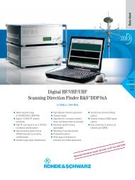
ApplicationsSWR measurementSimultaneous measurement of forwardand reflected power allows direct readoutof reflection coefficient, SWR orreturn loss.<strong>¸NRVD</strong>ROHDE & SCHWARZAB<strong>Power</strong> sensor A<strong>Power</strong> sensor BGeneratorGDUTDirectional couplerSweep tester with automaticfrequency response correctionFor correcting the frequency response ofa sensor, the <strong>¸NRVD</strong> is able to calculatethe test frequency from a voltageas is available at the sawtooth outputof a sweep generator. The result is aneasy-to-use sweep tester with automaticfrequency response correction.Sensor<strong>¸NRVD</strong>ROHDE & SCHWARZA BDC (FREQ) DC 1SweepgeneratorXYGDUTXYrecorderAttenuation measurementsThis setup is used for highly accurateattenuation measurements. By usinga reference sensor (A), test resultsare independent from generator levelvariations. The power splitter reducesmatching errors.<strong>¸NRVD</strong>ROHDE & SCHWARZAB<strong>Power</strong> sensor A<strong>Power</strong> sensor BGeneratorG<strong>Power</strong> splitterDUT<strong>Dual</strong>-<strong>Channel</strong> <strong>Power</strong> <strong>Meter</strong> <strong>¸NRVD</strong>
Probes¸URV5-Z7395.2615.02With 20 dB plug-on divider 1)With 40 dB plug-on divider 1)RF Probe200 µV to 10 V, 20 kHz to 1 GHz2 mV to 100 V, 1 MHz to 500 MHz20 mV to 1000 V, 500 kHz to 500 MHzFor measurements in RF circuits at low capacitive and resistive loadThe 20 dB and 40 dB plug-on dividers increase the voltage measurement range ofthe RF probe; the high Q factor of the capacitive divider makes the resistive loadingnegligible; the capacitive loading goes down to 0.5 pF (40 dB divider)With 50 W adapter¸URV-Z50With 75 W adapter¸URV-Z3¸URV5-Z1395.0512.02200 µV to 10 V, 20 kHz to 1 GHz With integrated termination for power or level measurements on test items with asource impedance of 50 W up to 1 GHz, BNC male/female connector200 µV to 10 V, 20 kHz to 500 MHz With integrated termination for power or level measurements in 75 W systems suchas antenna arrays or video equipment, BNC maleDC ProbesFor low-capacitance DC voltage measurements in RF circuits at minimum loading1 mV to 400 V, 9 MW ll 3 pF1)Part of ¸URV-Z6.Automatic filter setting depending on measurement rangeResolutionFilter numberHIGH 0.001 dB 11 9 7 7 7 7 7MEDIUM 0.01 dB 9 7 3 3 3 3 3LOW 0.1 dB 7 3 0 0 0 0 0¸NRV-Z1, -Z3, -Z4, -Z6, -Z15 10 nW 100 nW 1 µW 10 µW 100 µW 1 mW 20 mW¸NRV-Z2, -Z5 1 µW 10 µW 100 µW 1 mW 10 mW 100 mW 500 mW¸NRV-Z31 – 1 µW 10 µW 100 µW 1 mW 20 mW –¸NRV-Z32 – 100 µW 1 mW 10 mW 100 mW 2 (4) W –¸NRV-Z33 – 1 mW 10 mW 100 mW 1 W 20 W –¸NRV-Z51, -Z52, -Z55 10 µW 100 µW 1 mW 10 mW 100 mW – –¸NRV-Z53 1 mW 10 mW 100 mW 1 W 10 W – –¸NRV-Z54 10 mW 100 mW 1 W 10 W 30 W – –¸URV5-Z2, -Z7 – 1 mV 10 mV 100 mV 1 V 10 V –¸URV5-Z4 – 10 mV 100 mV 1 V 10 V 100 V –Measurement time in seconds (from trigger to output of first byte) depending on filter settingFilter number 0 1 2 3 4 5 6 7 8 9 10 11 12¸NRV-Z1 to -Z15 0.045 0.05 0.06 0.08 0.15 0.27 0.49 0.95 1.85 3.6 7.2 14.5 28.5¸NRV-Z31 model 02 1.04 1.04 1.05 1.07 1.13 1.24 1.44 1.84 2.7 4.3 7.5 14 27¸NRV-Z31/-Z33 model 03/04 0.135 0.14 0.15 0.17 0.23 0.34 0.54 0.94 1.77 3.4 6.6 13 26¸NRV-Z32 model 04 0.135 0.14 0.15 0.17 0.23 0.34 0.54 0.94 1.77 3.4 6.6 13 26¸NRV-Z32 model 05 0.435 0.44 0.45 0.47 0.53 0.64 0.84 1.24 2.07 3.7 6.9 14 27¸NRV-Z51 to -Z55 0.115 0.12 0.13 0.15 0.21 0.32 0.52 0.92 1.75 3.4 6.6 13 26¸URV5-Z2, -Z4, -Z7 0.065 0.07 0.08 0.10 0.20 0.38 0.72 1.45 2.8 5.5 11 22 44<strong>Dual</strong>-<strong>Channel</strong> <strong>Power</strong> <strong>Meter</strong> <strong>¸NRVD</strong>
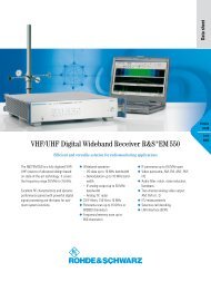
0.1 %0.5 %5 %1 VTransfer function at 33 °CP eU aTransducerϑU aP eTemperature sensor1 mV1 µV1 nW 10 µW 10 mW+ 5%Temperature response0%-10%023ϑ1 nW50 °CP20 mW+ 1dBFrequency response1 0–1.5 dB10 MHz 10 µW 10 GHzfThe individual calibration data is stored in a non-volatile memory in the connector of each sensor1.510 %VSWR S e n s or1.11 %2 %1.050.2 %1.021.02 1.05 1.11.5 2.0VSWRSourceLimits of power measurement error caused by mismatch of sensor andsignal sourceRear panel of the <strong>¸NRVD</strong>; for use in test systems, the unit is alsoavailable with rear-panel sensor inputs<strong>Dual</strong>-<strong>Channel</strong> <strong>Power</strong> <strong>Meter</strong> <strong>¸NRVD</strong>
Thermal <strong>Power</strong> Sensor¸NRV-Z 53SpecificationsMeasurement functionsFrequency and level rangeSensorsunmodulated and modulated power (average power, pulse power, peak envelope power, AM), reflection,DC and AC voltage (depending on sensor)DC to 40 GHz, 100 pW to 30 W (depending on sensor)all ¸NRV-Z and ¸URV5-Z voltage and power sensorDisplay LCD for figures, units, user prompting and analog display; adjustable backlightingReadoutAbsoluteRelativeNumeric displayAnalog displayW, dBm, V, dBV, dBµVdB, difference, %, ratio, referenced to a stored reference value or to the second measurement channel;SWR, reflection coefficient, return loss in dB, modulation depth with AMsingle-channel display: numeric readout of one channel and display of correction frequency or measurementuncertainty (not with all sensor) or dual-channel displaysingle-channel, automatic or with selectable scaleResolution of digital display5 digits max., resolution adjustable in 3 steps: HIGH: 12000 steps or 0.001 dB; MEDIUM: 1200 steps or0.01 dB; LOW: 120 steps or 0.1 dBAveraging filterover 1 to 512 readings for reducing the display noiseSetting manual or automatic setting depending on measurement range and resolution, see table on page 7Display noisesee data sheet of sensorsMeasurement rate see table on page 7Error limits of power readout in W (excluding sensor)18 °C to 28 °C 0.013 dB (0.3 %) + 1 digit10 °C to 40 °C 0.035 dB (0.8 %) + 1 digit0 °C to 50 °C 0.057 dB (1.3 %) + 1 digitZero adjustmentmanual or via IEC/IEEE bus, duration approx. 4 sFrequency response correctionstored frequency response of sensor taken into account by numeric entry of test frequency (manually orvia IEC/IEEE bus) or (optionally) by applying a frequency-proportional DC voltageAttenuation compensationattenuation or gain connected ahead taken into account; entry of attenuation value (±200 dB) viakeyboard or IEC/IEEE busReference valueone reference value per channel for relative measurements: numeric entry via keyboard or IEC/IEEE bus,use of stored measured value or current value of second channelReference impedancefor conversion between voltage and power, automatic readout of reference impedance from data memoryin sensor or numeric entry via keyboard or IEC/IEEE bus (for RF probe)Remote controlcontrol of all instrument functions via IEC 625/IEEE 488 interface in line with SCPI;interface functions: SH1, AH1, T6, L4, SR1, RL1, DC1, DT1, PP1Test generatorOutput power1.00 mW; factory set to ±0.7 % (traceable to PTB)Deviation from nominal1.2 % worst case (0.9 % RSS) at 0 °C to 50 °C for one yearFrequency50 MHzSWR ≤1.03RF connectorN female; N male/SMA female adapter for ¸NRV-Z6/-Z52/-Z15/-Z55 included<strong>Dual</strong>-<strong>Channel</strong> <strong>Power</strong> <strong>Meter</strong> <strong>¸NRVD</strong>
I/O Option <strong>¸NRVD</strong>-B2Analog outputsOutput impedanceVoltage rangeResolutionDC input for analog frequency response correctionVoltage rangeInput impedanceTrigger inputReady outputtwo, for simultaneous output of measurement results of both channels1 kW0 V to 3 V1 mV, deviation from nominal ≤5 mV±12 V1 MWTTL, active lowTTL, active highGeneral dataTemperature range meets EN 60068-2-1/EN 60068-2-2Operating 0 °C to +50 °CStorage –40 °C to +70 °CPermissible humiditySinusoidal vibrationRandom vibrationmax. 80 %, without condensation5 Hz to 55 Hz, max. 2 g; 55 Hz to 150 Hz, 0.5 g const. (meets EN 60068-2-6, IEC 1010-1 andMIL-T-28800 D, class 5)10 Hz to 500 Hz, 1.9 g rmsShock 40 g shock spectrum (in line with MIL-STD-810 D), meets EN 60068-2-27EMC meets EMC directive of EU, MIL-STD-461 C, RE 02, CE 03, RS 03, CS 02Safety meets EN 61010-1<strong>Power</strong> supplyDimensions (W × H × D), weightOrdering information100 V/120 V/220 V ±10 %, 230 V –6/+15 %, 47 Hz to 400 Hz, 25 VA219 mm × 147 mm × 350 mm, 4.5 kg<strong>Dual</strong>-<strong>Channel</strong> <strong>Power</strong> <strong>Meter</strong> <strong>¸NRVD</strong> 857.8008.02I/O Option <strong>¸NRVD</strong>-B2 857.8908.02Recommended extrasRack Adapter ¸ZZA-98 827.4533.00Service Kit <strong>¸NRVD</strong>-S1 1029.2808.02Certified Quality SystemISO 9001DQS REG. NO 1954 QMCertified Environmental SystemISO 14001DQS REG. NO 1954 UM¸ is a registered trademark of <strong>Rohde</strong> & <strong>Schwarz</strong> GmbH & Co. KG · Trade names are trademarks of the owners · Printed in Germany (Pe ch)PD 5213.5551.32 · <strong>¸NRVD</strong> · Version 04.00 · December 2005 · Data without tolerance limits is not binding · Subject to changewww.rohde-schwarz.comEurope: +49 1805 12 4242, customersupport@rohde-schwarz.comUSA and Canada: 1-888-837-8772, customer.support@rsa.rohde-schwarz.comAsia: +65 65130488, customersupport.asia@rohde-schwarz.com