Frequency-domain displacement sensing with a fiber ring-resonator ...
Frequency-domain displacement sensing with a fiber ring-resonator ...
Frequency-domain displacement sensing with a fiber ring-resonator ...

You also want an ePaper? Increase the reach of your titles
YUMPU automatically turns print PDFs into web optimized ePapers that Google loves.
This article was originally published in a journal published byElsevier, and the attached copy is provided by Elsevier for theauthor’s benefit and for the benefit of the author’s institution, fornon-commercial research and educational use including <strong>with</strong>outlimitation use in instruction at your institution, sending it to specificcolleagues that you know, and providing a copy to your institution’sadministrator.All other uses, reproduction and distribution, including <strong>with</strong>outlimitation commercial reprints, selling or licensing copies or access,or posting on open internet sites, your personal or institution’swebsite or repository, are prohibited. For exceptions, permissionmay be sought for such use through Elsevier’s permissions site at:http://www.elsevier.com/locate/permissionusematerial
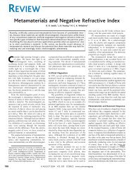
F. Vollmer, P. Fischer / Sensors and Actuators A 134 (2007) 410–413 411Fig. 1. (A) Ring-<strong>resonator</strong> <strong>with</strong> a variable gap, evanescently coupled to a buswaveguide. A tunable, narrow-linewidth laser is connected to the bus waveguideand a photodetector records the transmission spectrum. Profiling of a reflectingsample surface is possible for geometries where two <strong>fiber</strong> ends are aligned (B),or where a circulator is part of the <strong>ring</strong> (C).free-space part) of the <strong>fiber</strong>-loop:n eff C = mλ, (1)where n eff is an effective index used to describe the entire <strong>fiber</strong>loop<strong>resonator</strong> <strong>with</strong> unperturbed gap. n eff corresponds to theround-trip phase 2πn eff C/λ acquired by a resonant mode at λ.Ifthe waveguide part of the <strong>ring</strong>-<strong>resonator</strong> remains unperturbed,then a shift in the resonance wavelength occurs if either thedimension of the gap or the refractive index (medium) in thegap changes. We have recently shown that the latter can be usedto measure refractive indices and circular biref<strong>ring</strong>ences (opticalactivities) in the frequency <strong>domain</strong> [8]. A change L in the gapdimension results in a shift λ of the resonance wavelengthλλ= LC . (2)3. Experiments and resultsIn the present study the gap contains air and only its dimensionis changed. In its simplest form the gap is defined by twoaligned, cleaved waveguide ends (see Fig. 1A). However, differentgeometries allow for non-contact profiling of a partiallyreflecting surface (Fig. 1B), and use of a circulator allows <strong>displacement</strong>measurements <strong>with</strong> only one <strong>fiber</strong> or waveguide end(Fig. 1C).Our experiments are based on a <strong>fiber</strong>-loop <strong>ring</strong>-<strong>resonator</strong> (seeFig. 1A) built <strong>with</strong> a single mode 50/50 <strong>fiber</strong> coupler, where oneoutput port of the coupler is connected back to an input-port [3].The circumference of the <strong>ring</strong> is ∼0.63 m. A 20 mW tunable,narrow-linewidth, distributed feedback (DFB) laser diode operatingat ∼1311 nm nominal wavelength is connected to the buswaveguide through an optical isolator. The transmitted intensityis recorded by an InGaAs photodetector. We tune the laser frequencyby modulating the diode current <strong>with</strong> a saw-tooth shapedfunction. The laser diode tuning coefficient has been determined<strong>with</strong> a wavemeter and is ∼0.0067 nm/mA. The scan frequencyis typically 100–300 Hz, and 1000 points per transmission spectrumare recorded <strong>with</strong> a computer. The dynamic range in thepresent setup is limited due to real-time data analysis in Labview,but in principle the laser diode current could be modulatedat MHz to GHz frequencies. Resonances appear as Lorentzianshapeddips (Fig. 2A). The computer determines the reso-Fig. 2. (A) Transmission spectra of a ∼0.63 m <strong>fiber</strong>-loop <strong>ring</strong>-<strong>resonator</strong> <strong>with</strong> gapof length L ∼ 10 m, recorded <strong>with</strong> a tunable DFB laser of ∼1311 nm nominalwavelength. Resonances appear as Lorentzian dips <strong>with</strong> a finesse ∼7.8. Theinset shows the cleaved ends of the single mode <strong>fiber</strong>, 125 m in diameter. The<strong>fiber</strong> ends are aligned <strong>with</strong> two opposed, three-axis stages. (B) Transmissionspectra for the same <strong>fiber</strong> loop <strong>with</strong> a larger gap, L ∼ 300 m and finesse ∼2.8.The inset shows a picture of the aligned <strong>fiber</strong> ends.nance wavelength λ from the recorded transmission spectrum<strong>with</strong> a parabolic minimum fit using ∼20 points, and tracks itschange λ.A variable gap of nominal length L (insets in Fig. 2A andB) is introduced by cleaving the closed <strong>fiber</strong> loop at one pointand aligning the <strong>fiber</strong> ends using two, three-axis mechanicalstages equipped <strong>with</strong> piezoelectric actuators. Fig. 2A and Bshow the transmission spectra for two fixed gap lengths of L∼10 and ∼300 m <strong>with</strong> finesse of ∼7.8 and ∼2.8, respectively.The gap length can be changed by a small distanceL through modulation of the piezo actuators <strong>with</strong> a controlvoltage (64 mV P-P /m) set by an arbitrary waveform functiongenerator.In Fig. 3 we demonstrate that the shift of the resonancewavelength λ directly follows the gap <strong>displacement</strong> L.Fig. 3A depicts the gap and Fig. 3B the modulated gap lengthL (dotted line) and the corresponding shift of the resonancewavelength λ (solid line). The 3 Hz carrier is amplitudemodulated at 0.15 Hz, such that L changes by as much as±0.225 m.Author's personal copy
412 F. Vollmer, P. Fischer / Sensors and Actuators A 134 (2007) 410–4134. DiscussionFig. 3. (A) Illustration of a gap of variable <strong>displacement</strong> L. (B) The gap <strong>displacement</strong>L is modulated ±0.225 m <strong>with</strong> piezoelectric actuators and plottedvs. time (dotted line, <strong>displacement</strong> scale for L on right axis). The resonancewavelength shift λ of the <strong>ring</strong>-<strong>resonator</strong> is a direct measure of the gap <strong>displacement</strong>and plotted in the same graph (solid line, wavelength scale for λon left axis). (C) A gap <strong>displacement</strong> of L ∼ 10 nm is measured from thecorresponding shift λ (∼0.024 pm) of a resonance wavelength in a ∼0.63 m<strong>fiber</strong>-loop <strong>ring</strong>-<strong>resonator</strong>. (D) Shift of the resonance wavelength as a function of<strong>displacement</strong> (data from (B)), where the straight line is a linear fit to the data.An estimate of the sensitivity of the current setup <strong>with</strong> a∼0.63 m <strong>ring</strong> can be obtained from the data in Fig. 3C, where a∼10 m nominal gap length is modulated sinusoidally <strong>with</strong> anamplitude of L = 10 nm at 3 Hz. It is seen that subwavelength(∼10 nm) <strong>displacement</strong> measurements are already possible <strong>with</strong>the relatively large, low-finesse <strong>fiber</strong> loop <strong>resonator</strong>. The magnitudeof the associated wavelength shift λ is ∼0.024 pm, orabout 1/10th of the linewidth (∼0.28 pm, corresponding spectrumis shown in Fig. 3A). The shift of the resonance wavelengthλ is inversely proportional to the overall length (circumference)C of the <strong>ring</strong>-<strong>resonator</strong>, and is given by Eq. (2). It followsthat smaller <strong>ring</strong>-<strong>resonator</strong>s of similar geometry and linewidthallow for even smaller <strong>displacement</strong> measurements. From Eq.(2) it is seen that sub-nanometer sensitivity can be expectedfrom a <strong>fiber</strong>-loop <strong>resonator</strong> <strong>with</strong> a circumference ∼1 cm,which could be microfabricated or built from a tapered <strong>fiber</strong>[4].The current measurements are susceptible to overall drift.Common-mode noise may be eliminated by tracking the relativeshift between resonances [8]. For example in a geometrysuch as the one shown in Fig. 1C a mode can give rise to twodistinct resonances if in addition to the reflection at the surface,it is partially back reflected at the (possibly coated) <strong>fiber</strong>tip. In this configuration the <strong>ring</strong>-<strong>resonator</strong> may be applied inmeasurements where conventional (i.e. non-circular and mirrorbased)Fabry–Perot <strong>resonator</strong>s have been successfully used, e.g.,for thin-film characterization by <strong>displacement</strong> spectroscopy [14]or for <strong>fiber</strong>-optic vibration and <strong>displacement</strong> <strong>sensing</strong> [15,16]or for pressure <strong>sensing</strong> [17]. Similarly, it may be possible touse orthogonally polarized modes for relative shift measurements,provided the coupling of the modes can be suppressed[8].An increase in finesse and thus sensitivity of the <strong>ring</strong><strong>resonator</strong>can be expected, if optical losses are compensated for,e.g., by optical amplification as demonstrated for a closed <strong>fiber</strong>loop<strong>resonator</strong> that contains a section of pumped Erbium-doped<strong>fiber</strong> [18]. Furthermore, the <strong>fiber</strong> ends could hold provisionssuch as gradient refractive index lenses for efficient waveguidecoupling.5. ConclusionIn summary, we demonstrate that lateral <strong>displacement</strong>s can bemeasured in the frequency <strong>domain</strong> <strong>with</strong> a narrow-linewidth laserby tracking the resonance wavelength of a suitable <strong>resonator</strong>. Weshow that introduction of a gap enables a RR to be used for noncontactwaveguide-<strong>displacement</strong> measurements. A single mode,variable gap <strong>fiber</strong>-loop <strong>ring</strong>-<strong>resonator</strong> <strong>with</strong> a circumference of∼0.63 m connected to a tunable DFB is shown to be sensitiveto <strong>displacement</strong>s of ∼10 nm. Dramatically smaller waveguide<strong>displacement</strong>s should be measurable in rigid, micro-fabricated<strong>resonator</strong>s containing one or more gaps or in RRs that containan optical circulator.AcknowledgementsThe authors acknowledge Rowland Junior Fellowships andthank Chris Stokes for help <strong>with</strong> the electronics of the piezostagecontroller.References[1] P.L. Knight, A. Miller (Eds.), Steel Interferometry, Cambridge Studies inModern Optics (No. 1), Cambridge University Press, Cambridge, 1986.[2] H Hariharan, Interferometrs, in: M. Bass (Ed.), Handbook of Optics, vol.2, 2nd ed., McGraw-Hill, New York, 1995 (Chapter 21).[3] L.F. Stokes, M. Chodorow, H.J. Shaw, All-single-mode <strong>fiber</strong> <strong>resonator</strong>, Opt.Lett. 7 (1982) 288–290.[4] M. Sumetsky, Y. Dulashko, J.M. Fini, A. Hale, Optical micro<strong>fiber</strong> loop<strong>resonator</strong>, Appl. Phys. Lett. 86 (2005) 11611081–111611083.[5] J. Niehusmann, A. Vorckel, P.H. Bolivar, T. Wahbink, W. Henschel, H.Kurz, Ultrahigh-quality-factor silicon-on-insulator micro<strong>ring</strong> <strong>resonator</strong>,Opt. Lett. 29 (2004) 2861–2863.Author's personal copy