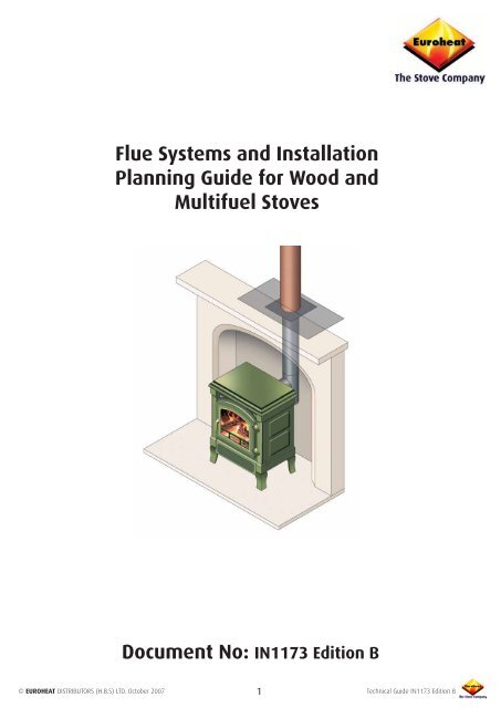
Flue Systems and Installation Planning Guide for Wood - Paul Burns ...
Flue Systems and Installation Planning Guide for Wood - Paul Burns ...
Flue Systems and Installation Planning Guide for Wood - Paul Burns ...

You also want an ePaper? Increase the reach of your titles
YUMPU automatically turns print PDFs into web optimized ePapers that Google loves.
flue is an anagram of fuel;both need to be correct ifyour stove is to work satisfactorily.Cannotbeassumed to workThe document has been written to highlight the importance of the flue in any stove installation <strong>and</strong> to give youan insight into why such an apparently simple item is far more complex than imagined when working.Although we have illustrated flue installations to show some of the many options available, this document is notintended to be an installation guide, <strong>and</strong> it should be noted that all flue installations <strong>and</strong> modifications to existingchimneys <strong>and</strong> flues are governed by so many regulations <strong>and</strong> legal requirements that no person should attemptany such work without being appropriately qualified.No installation should be undertaken unless the installer is suitably qualified or LocalAuthority Building Control Department permission has been granted.The installation, replacement of or alteration to the position of a solid fuel combustion appliance is subject toBuilding Regulations. Be<strong>for</strong>e proceeding with such works the householder is required by law to give building noticeor deposit full plans with the Local Authority Building Control Department <strong>and</strong> obtain permission to proceed.However, <strong>for</strong> Engl<strong>and</strong> <strong>and</strong> Wales, only, the coming into <strong>for</strong>ce on 1st April 2002 of SI 2002 No 440 exempts thehouseholder from this legal requirement <strong>for</strong> the installation of solid fuel fired appliance whose rated heat outputis 50kW or less in a building having no more than 3 storeys (excluding any basement) if a "Competent Engineer"is employed who is registered under the Registration Scheme <strong>for</strong> Companies <strong>and</strong> Engineers involved in the<strong>Installation</strong> <strong>and</strong> Maintenance of Domestic Solid Fuel Fired Equipment operated by HETAS Ltd. These registeredCompetent Engineers may also carry out associated building work necessary to ensure that the installed appliancecomplies with Building Regulations without involving the Local Authority Building Control Department.Further in<strong>for</strong>mation on the operation of Building Regulations <strong>and</strong> the exemptions under SI 2002 No 440 can beobtained from the Explanatory Booklet entitled “Building Regulations” which is available from the Office of theDeputy Prime Minister, PO Box 236, Wetherby, WestYorkshire, LS23 7NB.In Scotl<strong>and</strong> SI 2002 No 440 <strong>and</strong> its permitted exemptions do not apply. However, HETAS Ltd in its guide also listsunder the scheme contractors in Scotl<strong>and</strong> employing competent engineers which have met the HETAS scheme’srequirements <strong>for</strong> Registration.© EUROHEAT DISTRIBUTORS (H.B.S) LTD. October 2007 2Technical <strong>Guide</strong> IN1173 Edition B
If the chimney has a clay or salt glazed lining system it should be impervious to the effects of acids but thesystem was designed <strong>for</strong> open fires rather than a stove. The diameter will be bigger than many stoves require<strong>and</strong> the thermal losses through the clay to the masonry of the chimney will be large, so the problems of heatloss, tar deposits <strong>and</strong> condensation may manifest themselves as diluted tar running into the stove or appearingas dirty puddles on the hearth.If the existing flue is one of a number serving rooms in the house it will probably be found that the route takenfrom the room it is serving to the terminal will have nothing to do with any aspect of thermal per<strong>for</strong>mance, itwill be taken to facilitate a neat row of chimney pots at the top of the building. The routes taken were oftenpurposely made even more torturous to allow any rain falling down to hit almost horizontal sections <strong>and</strong> beabsorbed by the masonry rather than fall into the fireplace. While it is possible to coax a flexible stainless steelliner through many twists <strong>and</strong> turns, all changes of direction reduce the efficiency of the flue.The term "effective height" of a flue is the height of an equivalent flue that is vertical with no changes of direction.Each change of direction requires a vertical distance to provide the motivation to overcome the resistance to theflow of gasses these changes of direction impose. Various <strong>for</strong>mulae <strong>and</strong> "rules of thumb" giving the straightvertical length necessary to overcome each change of direction have been published. Care should be takenwhen using any of these because they give absolute angles with direction changes, something that is impossibleto achieve when using a flexible liner, <strong>and</strong> because many are based on gas burning appliances they have notallowed <strong>for</strong> differing surfaces, gas speeds, deposits in the flue <strong>and</strong> seldom adequately allow <strong>for</strong> heat losses in theflue because these will be unknown until the flue is operating, by which time the per<strong>for</strong>mance will be a realityrather than a theoretical estimation.If an existing flue has operated satisfactorily with an open fire it would be reasonable to assume that when linedwith the correct sized <strong>and</strong> insulated liner it will work with a multifuel stove. If you are not sure as to the flue'sper<strong>for</strong>mance look firstly at it its height, any flue less than 5 metres will be a potential problem. Check that theflue cross sectional area specified by the stove manufacturer can be accommodated <strong>and</strong> that if there are anychanges of direction that these can be negotiated with a flexible liner. Finally look to ensure it is possible toinsulate the liner adequately because this may be necessary rather than optional if the flue's route is complex.Back filling the void between the flue liner <strong>and</strong> existing flue way with vermiculite or other suitable insulatinggranules is both an effective insulation <strong>and</strong> a relatively simple operation.© EUROHEAT DISTRIBUTORS (H.B.S) LTD. October 2007 6Technical <strong>Guide</strong> IN1173 Edition B
Yet More Thermal Influences.Even be<strong>for</strong>e any wind blows a flue is affected by other factors, because a flue does not operate in isolation, it isa component of a system which includes the stove <strong>and</strong> house. Whilst we normally think of flues only when thestove is operating, the same rules of heat induced flow apply although the stove is not operating. If the houseis hotter than the outside air, the flue will gently draw air from the room if the stove's air controls are open.However, on those odd days when it suddenly becomes warm <strong>and</strong> the outside temperature is higher than thetemperature in the house, the flue will operate in reverse <strong>and</strong> draw down outside air, together with sooty smells,into the house, <strong>and</strong> <strong>for</strong> this reason the air control on the stove should be closed whenever the stove is not beingused. We call the phenomenon of downward flue flow the "Spring <strong>and</strong> Autumn Syndrome" because it is thesetimes of year it occurs <strong>and</strong> people have difficulty lighting their stove. The reversed air flow may provide sufficientair <strong>for</strong> the stove to ignite <strong>and</strong> burn poorly, but the products of combustion will spill into the house, <strong>and</strong> becauseso little of the heat from the stove is entering the flue the fire will either extinguish or fill the house with smoke.Solutions to the Spring Autumn Syndrome are detailed on page 31.A more complex example of thermally induced reversed flow in flues occurs in houses with multiple flues servingdifferent floor levels or low extensions with flue terminals well below the terminals of existing flues. The problemis made worse when natural, or advantageous, ventilation isreduced with improvements to door <strong>and</strong> window sealing, <strong>and</strong>the tendency <strong>for</strong> the taller flue to draw air down the shorter flueis increased, making the lighting of an appliance at the shortflue difficult. If the taller flue is being heated with an operatingappliance, air will almost certainly be drawn down the shorterflue, <strong>and</strong> if the outside temperature is colder than the insidetemperature, the room will be subjected to a flue smelling colddraught. This will make lighting an appliance at the shorter fluealmost impossible <strong>and</strong> it will inevitably be a smelly <strong>and</strong> smokytask. Installing adequate ventilation to the room with the shortflue will help, but the disparity between flue heights will alwaysbe a potential danger if they are being used at the same time.A typical example would be where both an open fire burning with a tall flue <strong>and</strong> generating a high flue draft <strong>and</strong>a stove with the short flue <strong>and</strong> generating a low <strong>and</strong> ideal flue draught are operating at the same time. Underthese conditions it is possible <strong>for</strong> the shorter flue to reverse its flow <strong>and</strong> the stove to emit poisonous products ofcombustion <strong>and</strong> not all of these gasses have an easily detected unpleasant smell. So far we have assumed onlyone tall flue, but the reality is that many houses have multiple flues that will be balanced against a single shortflue <strong>and</strong> the problem becomes <strong>and</strong> almost certainly a safety hazard. Installing a fan to assist the shorter flue isnot a solution because the fan will fail during a power cut, or may fail due to mechanical failures at any time. Ifthe shorter flue is the only one required in the property "capping off" the taller flues may be the only possibleoption if the shorter flue cannot be extended to the outlet levels of the other flues.© EUROHEAT DISTRIBUTORS (H.B.S) LTD. October 2007 7Technical <strong>Guide</strong> IN1173 Edition B
Looking at the Wind.Typical drawings to be found showing the effects of wind on flues illustrate a symmetrical house, "A" with highpressure areas on the windward side <strong>and</strong> low pressure areas on the leeward side. These drawings are similar tothose used in building manuals to show the loadings to walls <strong>and</strong> roofs caused by blocked <strong>and</strong> stalled air in highwinds. There is scant, if any, text with these drawings to explain why the wind would affect the flue draughtin the neat little house illustratrated. Explanations seen to be reserved <strong>for</strong> a drawing, "B" showing an additionalflue incorrectly terminating in either a high or low pressure area, <strong>and</strong> the permitted flue termination positionsallowed by the British St<strong>and</strong>ards are often given to support these sorts of drawings <strong>and</strong> whatever explanationsare given. Some illustrations go further byshowing what happens when a door orwindow is opened, again neatly directly onthe windward or leeward side of the house.The effect will of course be dramatic but doors<strong>and</strong> windows are seldom opened on a coldwindy day <strong>and</strong> the drawings explain nothingabout why a flue should work as an extractionsystem when the wind blows <strong>and</strong> the doors <strong>and</strong>windows are tightly closed to conserve heat.Even those with little interest in science <strong>and</strong> have never heard of Bernoulli's Principle will know that a fast movingtrain or car tends to draw you towards it as it passes. You need know nothing about Ludwig Pr<strong>and</strong>tl to knowaeroplanes fly, but even if you paid no attention to science at school you might like to know that not st<strong>and</strong>ingclose to a station plat<strong>for</strong>m edge, aeroplanes flight, <strong>and</strong> wind causing havoc to flue draught are <strong>for</strong> the samereason.As a child you may have blown over a piece of paper to cause it to lift, if not, now is your opportunity to holdthe edge of a piece of paper horizontally just below your bottom lip <strong>and</strong> blow, this will cause the whole pieceof paper to lift horizontally because the air above the paper is travelling faster, with a lower pressure, than theair below the paper. Looking at an aeroplane wing will reveal that its top surface is much more rounded than itsunderside which means that air passing over the top of the wing has to travel further <strong>and</strong> there<strong>for</strong>e faster thanthe air passing the underside of the wing. Because the air is travelling faster its pressure reduces <strong>and</strong> so the upperwing surface is pulled upwards. If you have ever stood on a cold, windy, station plat<strong>for</strong>m you might not agreethat the air is relatively static but compared with the air being <strong>for</strong>ced to push around a fast moving train it is. Theair at the plat<strong>for</strong>m is at a higher pressure than the air surrounding the fast moving train <strong>and</strong> so you are pulledtowards the train as it passes. The same happens when wind blows over a house, the air, having to travel over<strong>and</strong> around the house, has to travel further <strong>and</strong> faster to keep up with the general flow <strong>and</strong> its pressure drops,so air passing over the flue terminal will be at a lower pressure than the air within the house, causing the flue toexhaust more easily whenever the wind blows.If you are beginning to grasp the theory of pressure dropping with air speed you might like to contemplate whathappens when a ball is thrown with <strong>and</strong> without a spin. Or, if you have a ping pong ball <strong>and</strong> a vacuum cleanerthat will blow through the hose, try balancing the ball on the vertical stream of air, it is easier than imagined <strong>and</strong>it balances <strong>for</strong> the same reason that wind induces flue draught.© EUROHEAT DISTRIBUTORS (H.B.S) LTD. October 2007 8Technical <strong>Guide</strong> IN1173 Edition B
Knowing the cause of increased flue draught when the wind blowsshould make it easier to control, but we have only found the primesource <strong>and</strong> we need to look at the other influential factors. Goingback to our little simplistic house being subjected to wind we c<strong>and</strong>raw the air flow travelling over the roof <strong>and</strong> it becomes obvioushow much further the air has to travel to pass over the roof. Wecan illustrate the area of low pressure with shading where the airreaches its highest speeds but however simplistic we make thedrawing the profile of the house is very different from an aeroplanewing <strong>and</strong> the smooth flowing lines showing the air as travelling inconvenient lamina strata are unrealistic because air will only holdtogether if the changes of direction are smooth <strong>and</strong> proportioned toits speed. A house roof <strong>and</strong> chimney are not shaped to give smoothair flow <strong>and</strong> the abrupt changes of direction they cause the air flowto take results in the air flow fragmenting to <strong>for</strong>m pockets that spin<strong>and</strong> travel in differing directions as the wind speed increases.Because the directions of these pockets of air are often oppositeto that of the main flow they briefly <strong>for</strong>m zones of high pressurewhich may cause the flue system to stall or even reverse flowmomentarily. If you can bring yourself to st<strong>and</strong> <strong>and</strong> look at theterminal when a wind is accompanied by snow, the confused airflow will be seen easily. Early chimney builders knew nothingabout the science of air flow but they knew that putting a chimneyterminal high above the roof lessened the tendency of the flueto have a draught fluctuating between positive <strong>and</strong> negativewith each wind gust. The humble chimney pot took the terminalaway from even the turbulence caused by the straight sides <strong>and</strong>squared edges of the chimney stack. The stove manufacturerswho underst<strong>and</strong> flue draught have always tried to reduce thecross sectional area of the flue to the minimum possible, not onlyto reduce the thermal losses through the flue walls but becausethe area exposed to wind induced draught will also be minimised. Some more modern houses have often beenbuilt with little or no consideration to flue per<strong>for</strong>mance <strong>and</strong> often have the terminal only just higher than theroof ridge, causing the terminal to be in the worst area of changing pressures. In very recently built houses youmight notice the terminations below the roof ridge, this is not because of a reversal of scientific knowledge butrather a chimney with no flue way, put up as a non-functional roof ornamentation.So far we have looked at the wind induced flue draught associated with our little symmetrical, two dimensional,house, but it is enough that we underst<strong>and</strong> the very basics of what is happening when the wind blows over ahouse. Trying to analyse what happens when a multi chimney, asymmetrical house is subjected to wind willproduce differing results with each small change of wind direction <strong>and</strong> would make aeronautics look like child'splay. Again, watching the terminal during a snow storm will demonstrate what is happening when the windtravels over the roof <strong>and</strong> terminal <strong>and</strong> this will be especially interesting because you can relate it to the way thewind is affecting the stove's per<strong>for</strong>mance.What part Ludwig Pr<strong>and</strong>tl plays in some aeroplanes having the abilityto fly upside down will be discussed in a later document.© EUROHEAT DISTRIBUTORS (H.B.S) LTD. October 2007 9Technical <strong>Guide</strong> IN1173 Edition B
Whilst we are not going to look at wind passing over the house in any more detail several other issues that affectthe wind induced draught need to be looked at. Firstly if all this air is travelling up the flue it needs to be replacedwith air entering the house <strong>and</strong> how we do this in a planned manner will be looked at later but all doors <strong>and</strong>opened windows will affect the flue's per<strong>for</strong>mance. An opening to the windward side will increase the draught<strong>and</strong> opening to the leeward side will reduce the draught <strong>and</strong> if you have been paying attention you will knowthat wind rushing past open windows midway between windward <strong>and</strong> leeward will reduce the flue draught.Having looked at the house itself it is important that its location <strong>and</strong> surroundings are looked at to see how theywill affect the wind be<strong>for</strong>e it reaches the house. Much of this will be an educated guess because again it willchange with each change of wind direction <strong>and</strong> the permutations are endless, but it is possible to identify somepotential problems by looking at the contours of the ground which will affect the wind.If be<strong>for</strong>e looking <strong>for</strong> potential problems with the property that may be caused by obstructions nearby, a far widerarea should be looked at, taking time to look at other chimneys. If every old house nearby has what seems to bea disproportionately tall chimney it will be because of difficult wind patterns in the area <strong>and</strong> not because everybuilder liked working at high altitudes.Obstructions near to the property may cause problems <strong>and</strong> trees in particular should be noted because withoutleaves they may have little or no effect on the passage of wind but when the stove is operated during the coldspells in spring when the trees are in leaf they may cause havoc to the flue draught; not having caused a problemall through the winter they are often overlooked as the cause of any flue problems. For similar reasons trees thathave been planted <strong>for</strong> many years may not have caused a problem, but one year they may reach a critical height<strong>and</strong> width to completely disrupt the wind flow.There is rarely a simple <strong>and</strong> totally satisfactory solution to overcoming the problems with the effects of windturbulence.© EUROHEAT DISTRIBUTORS (H.B.S) LTD. October 2007 10Technical <strong>Guide</strong> IN1173 Edition B
Methods of Controlling the <strong>Flue</strong>.The Barometric Damper.If there is to be any hope of controlling the flue it must be installed to put the terminal in the best possibleposition, it must have sufficient height <strong>and</strong> it must maintain temperature. So returning to the situation wherethe flue needs to operate on a mild, still day there will be too much negative pressure on a cold day, when thedensity differences between the atmosphere <strong>and</strong> the flue gasses are greater. If we add a strong wind to ourcold day the result would be far too much flue draught. The device <strong>for</strong> sorting out this little problem is called a“barometric damper” or “flue stabilizer”, which can be fitted to the flue. It consists of a hinged flap with the hingepoint above the centre point so the flap always tends to adopt the closed position. As the air pressure within theflue falls, the air on the outer side of the flap pushes the flap open, spilling air into the flue way this immediatelyreduces the excessive air flow through the stove <strong>and</strong> because the air allowed into the flue is relatively cold slowsthe flue's thermally induced flow. An adjustable counterbalance weight allows the flap to be held closed until thenecessary pressure difference has been reached.With the draught pressurebelow its set point thestabilizer remains closed.Draught Stabilizer <strong>Installation</strong>When the draught pressureexceeds its maximum theflap opens to spill in cool air.The adjustable counter balanceallows the damper to be setcorrectly <strong>for</strong> a wide range of flues.1. A stabilizer must have the same cross sectional area as the flue.2. The stabilizer must be fitted to the manufacturers instructions<strong>and</strong> must not be modified.3. The stabilizer should ideally be fitted no closer than 600mm to theflue outlet of the appliance. In certain instances where there is notenough clearance above the stove to give 600mm it is permissableto fit the stabilizer closer to the flue outlet, however it should neverbe fitted less than 300mm from the flue outlet.600mm300mm4. The flue stabilizer should be fitted in the same room as the stoveinstallation.5. Where a flue draught stabilizer is used the total free air areashould be 300mm² <strong>for</strong> each kW/hr of rated output of the stoveup to 5kW. Above 5kW of rated output the free air area should be850mm² per kW above 5kW11© EUROHEAT DISTRIBUTORS (H.B.S) LTD. October 2007 Technical <strong>Guide</strong> IN1173 Edition B
The Chimney Cowl.We now move to the top of the flue <strong>and</strong> look at the terminal itself. While you were outside watching the snowswirling <strong>and</strong> travelling in any direction other than those drawn in “wind passing terminal” drawings you may havenoticed that the simple chimney pot, which has been used <strong>for</strong> hundreds of years, is finally being replaced by morescientific terminals. With so many diverse shapes <strong>and</strong> sizes you would be <strong>for</strong>given <strong>for</strong> wondering which sciencethey were based on, <strong>and</strong> indeed many of us wonder. In an age where technology with computer modelling <strong>and</strong>all the necessary test equipment have narrowed the discrepancies between the designs of solutions to problemsit is interesting that cowls would seem to be the exception. But perhaps even more interesting is that each cowldesign will have a number of people who regard it to be a perfect solution <strong>and</strong> a similar number of people whoregard it as worse than useless. None of them will prevent the low pressure zone over the house when the windblows but they can smooth or redirect the flow of air at the terminal, changing the effect that wind has on theflue.In its simplest <strong>for</strong>m the chimney cowl is nothing more than a rain cap. These were unnecessary in a brick chimneybecause most of the rain falling down was absorbed by the bricks <strong>and</strong> the absorbed water evaporated outwhenever the fire was lit. With appliances like stoves so little heat is wasted that we have to line <strong>and</strong> insulatethe flue which gives rain a direct passage to the stove. The following drawings show that fitting a rain cap on achimney pot will almost reverse the effect of vertically rising or falling wind.Almost all winds moving in an upward direction will be caught by the cowl to <strong>for</strong>m an area of high pressure abovethe flue, but wind moving in a downward direction will also be able to blow into the flue as its angle decreases.When this angle is reached the effect will be a sudden change <strong>and</strong> all sudden changes are difficult to control.Changing the diameter of the cowl <strong>and</strong> its height above the flue in an attempt to stop this will make the flue worsein upward wind directions or let the rain in. Be<strong>for</strong>e dismissing the simple rain cap cowl it must be rememberedthat we have given no consideration to effects the house itself will have on the wind direction <strong>and</strong> those togetherwith other pressure factors might make a cowl like this of certain proportions the perfect terminal.It is this unknown element which makes the choice of cowl so difficult. A cowl which gives the solution to oneproblem flue may exacerbate the problems of a flue with a seemingly identical problem in a similar house ina different location, but cowls can be put into very loose categories as to their purpose. Whilst almost all cowlsclaim to be “anti down draught” others purport to do more.The left h<strong>and</strong> snorkel is mounted on the chimney pot on a bearing allowing it to be rotated by wind blowing atits vane <strong>and</strong> causing the opening to face down wind consistently. Whilst solving some problems, by maximizingthe effect of wind, the resultant difference in flue draught between wind <strong>and</strong> windless conditions is too great <strong>for</strong>any stove <strong>and</strong> draught control system to cope with. The cowl on the right is often seen as an enormous terracottaaffair on low or badly sited old chimneys <strong>and</strong> works by ensuring that all air passing is redirected, resulting in allair flow causing air to be drawn out of the flue. This cowl manages to cope with almost every wind direction<strong>and</strong> a modern, light weight version is available, but as with the snorkel it tends to amplify the differences in theflue’s per<strong>for</strong>mance.© EUROHEAT DISTRIBUTORS (H.B.S) LTD. October 2007 12Technical <strong>Guide</strong> IN1173 Edition B
There are many variations using the basic principles of these cowls with varying degrees of success but all arecapable of increasing the flue draught beyond the limitation of our control <strong>for</strong> stoves because they were originallydesigned <strong>for</strong> open fires.Another approach to a cowl which should give less variation in wind generated flue draught is to cover the mouthof the flue with a box vented with slots, louvers or course mesh in an attempt to slow the wind speed passingthe mouth of the flue. These may slow the air speed but because the box will need to be large enough to spreadthe area of the flue diameter it creates its own negative pressure on the downwind side while the upwind side,if the slots are doing anything at all will be limiting the higher pressure entering. The net result will be a slowerair flow but an increase in the negative pressure over the flue mouth caused by the box obstructing the air flow<strong>and</strong> creating a negative pressure pocket on the downwind side. The effects of winds blowing in anything buta horizontal direction will depend on many things but the angle of the air stream may be such that it is notprevented from acting directly onto the flue mouth. Increasing the diameter of the box to prevent this will onlyincrease the negative pressures generated at the downwind side.Another solution to the problem of varying wind speed is to direct air passing over the flue downwards, <strong>and</strong> socreate a high pressure zone above the flue which is proportional to the negative pressure <strong>and</strong> thereby cancellingeach other out.If the flue terminal was some hundred feet in the air, with nothing but flat l<strong>and</strong> <strong>for</strong> a radius of a mile, the airwould be passing the terminal in only one plane <strong>and</strong> this would work well. However flue terminals do not existin isolation, they exist in close proximity to obstructions which divert the wind to act in many planes which willvary with wind direction. Whatever shape above the flue caused a high pressure zone when the wind passed ithorizontally will not produce an identical effect with an air stream at anything other than horizontal flow. It canbe improved by adding disks to divert the air into a horizontal flow <strong>and</strong> these will improve the ability to cope withair flow away from the horizontal, but the efficacy of the discs will be related to their diameter <strong>and</strong> at some pointaway from horizontal the air will simply slip past the discs. At the point at which the discs fail they will only serveto increase the effective diameter of the flue resulting in a greater negative pressure if the air stream is upwards.What happens when the air stream is downwards will depend on the proximity of any obstruction.© EUROHEAT DISTRIBUTORS (H.B.S) LTD. October 2007 13Technical <strong>Guide</strong> IN1173 Edition B
A more complex approach to the problem is the range of cowls that would seem to have been designed on akitchen table using an assortment of mixing bowls. These cowls are designed to divert the air over the largerbowl creating a high pressure zone at the middle. This bowl has an open top through which a smaller bowlprotrudes. The high pressure restricts the flue gasses passing up through the cowl, sending them downwards toexit under the rim of the larger bowl. The shape <strong>and</strong> combination of the two bowls restricts the air flow out ofthe cowl when the air stream is in an upwards direction creating a positive pressure to counteract the negativepressure that would have been created above the flue mouth. The effect of a downwards flowing air stream willbe diverted away from the flue mouth <strong>and</strong> again the combination of openings at the top <strong>and</strong> bottom of the largerbowl will prevent flue down draught affecting the flue. Un<strong>for</strong>tunately, the differing sizes <strong>and</strong> shapes of the dishesmeans that their influence will not remain consistent with each <strong>for</strong> all wind speeds <strong>and</strong> all directions.No cowl will solve all problems <strong>and</strong> no cowl will per<strong>for</strong>m identically in every installation because no flue operatesconsistently. A flue which is operating at a low temperature is very different to one operating at its maximumtemperature <strong>and</strong> flow rate. Cowls are tested as an isolated piece of equipment <strong>and</strong> some cowl manufacturersrecognize that so many other factors will affect its per<strong>for</strong>mance that they offer a guarantee to accept its return ifit fails to per<strong>for</strong>m as anticipated in any particular installation. Although this gives the opportunity to try severalcowls, simply fitting cowls r<strong>and</strong>omly is not recommended because the novelty of scaffolding <strong>and</strong> the adrenalinerush of roof walking are fickle emotions <strong>and</strong> may evaporate be<strong>for</strong>e you find a suitable model. The correct choiceof cowl is often a case of two wrongs nearly making a right <strong>and</strong> be<strong>for</strong>e seeking the advice of cowl manufacturersyou should identify what the problem is <strong>and</strong> if possible rectify it be<strong>for</strong>e resorting to the expense of having acomplex cowl fitted. © EUROHEAT DISTRIBUTORS (H.B.S) LTD. October 2007 14Technical <strong>Guide</strong> IN1173 Edition B
Cowl <strong>Installation</strong>A cowl must be fitted to a chimney pot to raise the cowl away from the chimney brickwork. The pot must be inperfect condition <strong>and</strong> be securely embedded into the chimney masonry. Do not fit a cowl to any other than asimple pot, those with louvers or any ornementation are unsuitable.XXXManufacturers' InstructionsThe manufacturers' fitting instructions must be followed implicitely, no improvised fixing methods or alternativepositioning should be used. Some cowls have extra security fittings available as an optional extra if you live inan exeptionally windy area. Ensure the cowl is approved <strong>for</strong> solid fuel combustion.XXXXCowl <strong>and</strong> LinerThe liner must extend to the mouth of the chimney pot. If the liner terminates at the base of the pot, the cowl maynot per<strong>for</strong>m as it is designed to do, due to increase in diameter, <strong>and</strong> heat losses caused by the cold pot will causeturbulance. The liner must have asupport plate fitted to secure the liner<strong>and</strong> the cowl must be fitted exactlyto the manufacturers' instructions.If room exists an insulating materialsuch as glassfibre wool can be fittedbetween the liner <strong>and</strong> pot.X© EUROHEAT DISTRIBUTORS (H.B.S) LTD. October 2007 15Technical <strong>Guide</strong> IN1173 Edition B
<strong>Installation</strong> into an Existing ChimneyInsulationCowl to preventingress of rain, birds<strong>and</strong> to assist with fluestabilization.<strong>Flue</strong> liner reaching to top of thetermination <strong>and</strong> insulated.<strong>Flue</strong> liner support collar whichis required <strong>for</strong> both flexible <strong>and</strong>single wall liners.Weatherproof chimneycapping <strong>and</strong> pot.XSound chimney brick work.Stainless steel liner.<strong>Flue</strong> height 5m or more.Flexible to single walladapter if flexible lineris fitted.Register plate preventing theescape of heat, positionedas low as practicable to aidconvection.Access <strong>for</strong> cleaning.Level <strong>and</strong> stable supportinghearth.Sufficient clearance behind stove <strong>for</strong>maintenance <strong>and</strong> to allow the air tocirculate to <strong>and</strong> from the stove .The diagram above shows an unsuitable installation.A masonary chimney which has not been lined.Unstable brick work within the chimney allowing soot to betrapped so increasing the chance of a chimney fire.Unstable chimney pot.The stove installed with no clearance behind it.The flue pipe installed at an angle.No cleaning access to either the flue pipe or chimney.The total height of the flue less than 4m.No cowl fitted to prevent ingress of rain, birds <strong>and</strong>/or to assistwith flue stabilization.© EUROHEAT DISTRIBUTORS (H.B.S) LTD. October 2007 16Technical <strong>Guide</strong> IN1173 Edition B
<strong>Installation</strong> into an Existing ChimneyMaximum 150mmhorizontal runCleaningaccessAccess <strong>for</strong> cleaning, minimumhorizontal path, 150mm or less.With no flue liner fitted, no access <strong>for</strong> cleaning<strong>and</strong> positioned on an insufficient hearth makesthis installation dangerous <strong>and</strong> illegal.Register plate incorrect positionAccess door<strong>for</strong> cleaningRegister plate toohigh, allowing hotair to accumulatewithin the fireplaceT piecedebris trapStove positioned to allowheated air from the stove tocirculate easily <strong>for</strong> cleaningWith no flue liner fitted, incorrect 90 degreebend badly fitted, no protection against flueblockage, no access <strong>for</strong> cleaning <strong>and</strong> thestove badly positioned on an insufficienthearth makes this installation dangerous<strong>and</strong> illegal.© EUROHEAT DISTRIBUTORS (H.B.S) LTD. October 2007 17Technical <strong>Guide</strong> IN1173 Edition B
Register PlateIf an existing fireplace is to be used to house the stove all but an opening to allow the new flue pipe of the originalflueway throat will need to be sealed off. This plate is called a register or closure plate <strong>and</strong> needs to be givenmore than a little thought. The plate must be manufactured using 1.5mm thick rust resistant metal to con<strong>for</strong>mto building regulations. If the plate is to be painted, do not use ordinary household paint, it must be a heat proofpaint. If the space between the old flue <strong>and</strong> new liner is to be back filled with vermiculite or similar insulatingmaterial the a steel plate can be one complete sheet but if the space is not to be insulated a closable apertureshould be made in the plate to allowthe removal of debris that willinevitably collect as the chimneydrys <strong>and</strong> combustable deposits fallfrom the brickwork.The plate should be secured byfixing a continuous ledge of angleiron around the opening, fill withmortar any gaps left by unevenbrickwork <strong>and</strong> screw the registerplate to the angle iron. This not onlygives a very secure fixing it alsoallows its removal <strong>and</strong> replacementto be done simply <strong>and</strong> quickly ifaccess is ever required.The position of the register plate is a conflict between being irritated by seeing the plate <strong>and</strong> the need to haveair flowing around the stove, circulating to the room easily. Positioning the plate high into the throat of the flueway will render it invisible but it will trap hot air from the stove that should be heating the room rather thanthe masonry of the fire place. Do not be missled into believing that the masonry becomes a heat store becausea high proportion of this heat will be lost if the chimney is against an outside wall. A well fitted plate paintedin a suitable colour, with heat proof paint, will eventually become all but invisible, but the loss of heat will be aconstant expense <strong>and</strong> irritation when the room gains temperature too slowly <strong>and</strong> looses it rapidly.XIf you are tempted tofit concealed lightingto illuminate the spacebehind the stove, yourelectrician must bemade aware of the hightemperatures that thefireplace <strong>and</strong> especiallythe register plate willoperate at, <strong>and</strong> thatordinary fittings, cable<strong>and</strong> even light bulbswill be unsuitable.These considerationswill apply even if thelights are intendedto be illuminated onlywhen the stove is notoperating.© EUROHEAT DISTRIBUTORS (H.B.S) LTD. October 2007 18Technical <strong>Guide</strong> IN1173 Edition B
VentilationHaving achieved a reliable flue draught to exhaust the products of combustion our attention now turns to thesupply of fresh air, <strong>and</strong> it will come as no surprise to learn that getting air into the house is almost as complicatedas it was pushing it up the flue. If the stove has the facility to draw its air <strong>for</strong> combustion directly from outsideof the property no additional ventilation but it is law that a stove has sufficient ventilation into the room it isinstalled if it is supplied with air from that room. The legal requirements <strong>for</strong> ventilation give the size of ventilationthat must be fitted to achieve sufficient air supply <strong>for</strong> specific stove sizes. The term "equivalent area" has takenover the old term of "free air" because so many ventilation grills were available that purported to allow air flowwith no draughts. Given that draught is air flow I have no idea what science they were based upon but many werelittle more than a complicated obstruction behind the opening grill to restrict the air flow <strong>and</strong> hence the need<strong>for</strong> all ventilation grills to be marked with their effective air flow. With the law requiring us to fit a permanent,meaning one that cannot be closed, ventilator of a specific size, we now have to find a suitable position to installit. The legal requirement is <strong>for</strong> the area of ventilation but makes no mention of this area being achieved witha single or multiple ventilators nor where they should be positioned, apart from allowing air from outside theproperty directly to the room in question,Our little house has not had the wall removed <strong>for</strong> ventilation but tosimplify my drawing of the air coming in at the left side <strong>and</strong> blowingup the chimney. If the ventilator is in a wall facing the wind it willbe subjected to a high pressure as the air struggles to find its wayaround the obstruction. This will obviously cause a great deal of airto enter the ventilator, slightly pressurising the house <strong>and</strong> ensuringthe stove has a more than adequate air supply. If the ventilator ispositioned at the opposite end of the room to the stove the roomwill be subjected to a draught, whatever patented draught reducingdevice may be fitted <strong>and</strong> this air will obviously be cold or therewould be no reason to have lit the stove. For how long differingpeople will tolerate a cold draught be<strong>for</strong>e becoming irritated is theproverbial piece of string, but the string will eventually snap <strong>for</strong>everyone <strong>and</strong> the ventilator will be at least partially blocked withan item of furniture or piece of card. This might not be a problem if the wind is strong <strong>and</strong> facing directly at theventilator, but all winds eventually blow themselves out leaving the property with an insufficient air supplybecause it is unlikely that the obstruction will be removed. It is there<strong>for</strong>e important to position the ventilationpoint as close to the stove as possible to minimise the cold air passing through <strong>and</strong> cooling the room <strong>and</strong> itsoccupants.What happens when the wind blows inthe completely opposite direction will bethe complete opposite to the previousexample. The ventilator will now be facingthe low pressure side of the house <strong>and</strong>any wind blowing will tend to cause theventilator to evacuate rater than supplyair to the house. This is obviously anunsatisfactory situation <strong>and</strong> by knowingthat if air is rushing past the ventilator theventilator will again evacuate rather thansupply air we have our ventilator supplyingair only when the wind is blowing fromone of the four possible directions. (Amore obscure example of a ventilator working to evacuate rather than supply air is where the vent has beenfitted to a wall very close to a road <strong>and</strong> is affected by every large vehicle passing.) As with all the effects of windwe have looked at, the reality is far more complex than wind coming from neatly defined directions to hit ourlittle symetrical house, <strong>and</strong> ensuring reliable ventilation whatever the wind is doing is something that cannot beachieved easily <strong>and</strong> is often overlooked as the cause of a badly per<strong>for</strong>ming flue.© EUROHEAT DISTRIBUTORS (H.B.S) LTD. October 2007 19Technical <strong>Guide</strong> IN1173 Edition B
Further Regulations Applicable to a House with an "easily ignited roofcovering"1800mmA600mmBBAt least2300mmAt least1800mmOutlets shouldbe above theshaded areasAreaABLocation of flue outletat least 1800 mm vertically above the weather surface<strong>and</strong> at least 600 mm above the ridgeat least 1800 mm vertically above the weather surface <strong>and</strong> atleast 2300 mm horizontally from the weather surfaceSundry Items of Legislation That Govern <strong>Installation</strong>s.Debris Collection SpaceWhere a chimney cannot be cleaned through the appliance, a debris collecting space which is accessible<strong>for</strong> emptying, <strong>and</strong> suitable sized opening(s) <strong>for</strong> cleaning should be provided at appropriate locations in thechimney.Masonry <strong>and</strong> <strong>Flue</strong> Block ChimneyMasonry chimneys should be built in accordance with Document J paragraphs 1.27 <strong>and</strong> 1.28. <strong>Flue</strong> block chimneyswould be built in accordance with Document J paragraphs 1.29 <strong>and</strong> 1.30. The thickness of the walls around theflues, excluding the thickness of any flue liners shall be in accordance with Document J diagram 2.4.Separation of Combustible Material from Fireplaces <strong>and</strong> <strong>Flue</strong>sCombustible material should not be located where it could be ignited by the heat dissipating through the wallsof fireplaces or flues. A way of meeting the requirement would be to follow the guidance in Document J diagram2.5 so that combustible material is at least:a) 200 mm from the inside surface of a flue or fireplace recess; orb) 40 mm from the outer surface of a masonry chimney or fireplace recess unless it is a floorboard, skirtingboard, dado or picture rail, mantel-shelf or architrave. Metal fixings in contact with combustible materials shouldbe at least 50 mm from the inside surface of a flue.© EUROHEAT DISTRIBUTORS (H.B.S) LTD. October 2007 22Technical <strong>Guide</strong> IN1173 Edition B
Pre-fabricated <strong>Flue</strong>sMade in interlocking sections with a stainless steel outer casing surrounding high per<strong>for</strong>mance insulation <strong>and</strong> aflue liner made of stainless steel. Some systems have a ceramic or refractory concrete flue liner which offers evenbetter resistance to corrosion.The metal lined systems should give a normal life of 10 to 15 years or more when correctly installed, operated <strong>and</strong>maintained. However, prolonged periods of slow burning particularly using solid fuels, combined with inadequatecleaning of the flueways can cause corrosion damage which may reduce the expected life of the liner. If there isa risk that these conditions can occur the non-metallic lined systems are a better choice <strong>and</strong> under normal useshould give a life in excess of 20 years.APPROVALSThese systems must have a British St<strong>and</strong>ard Kitemark to BS 4543:1990 (1996) Part 2 (Note: Part 3 deals only with suitability <strong>for</strong> oilfiring systems) or to BS EN 1856-1: 2003. Alternatively a BSRIAcertificate or similar test reporting e.g. by TÜV that indicatesthe product can satisfy Building Regulation requirements withrespect to the burning of solid fuel. The Approval Status listed<strong>for</strong> the products was correct at the time of printing but it isrecommended that the manufacturer be consulted on the currentapproval status prior to specification or purchase of the product.NOTE: BS 4543 was withdrawn in March 2005. It was replacedby BS EN 1856-1:2003. Products meeting the requirement ofthe 2002 Edition of Approved Document J <strong>and</strong> the ‘ApprovedDocument J: 2002 Edition: Guidance <strong>and</strong> SupplementaryIn<strong>for</strong>mation on the UK Implementation of European St<strong>and</strong>ards<strong>for</strong> Chimneys <strong>and</strong> <strong>Flue</strong>s should have an equivalent designationaccording to BS EN 1856-1 of T400 N1 D Vm L40040 Gxx whereL40040 is the minimum material specification in the NationalAnnex to BS EN 1856-1 <strong>and</strong> xx is the necessary separation fromcombustible materials, when the product is tested in the fullyenclosed arrangement specified in BS EN 1859:2000 includingfirestops. Alternatively products may have the designation T400N1 D V3 L40040 Gxx having been independently tested <strong>for</strong> theircorrosion resistance according to Annex A3 of BS EN 1856-1:2003.Such products will carry a CE mark.IMPORTANTThe manufacturers, instructions <strong>for</strong> the installation of the fluesystems must be complied with at all times.© EUROHEAT DISTRIBUTORS (H.B.S) LTD. October 2007 23Technical <strong>Guide</strong> IN1173 Edition B
<strong>Installation</strong> into a <strong>Flue</strong> Block SystemFactory Made Precast Block Built ChimneysPrecast concrete blocks incorporating a flue way <strong>for</strong> building into brick or block walls, or freest<strong>and</strong>ing over limitedheights. These lightweight units are easy to h<strong>and</strong>le <strong>and</strong> there<strong>for</strong>e can offer a reduction in the cost of installing achimney in a new house. The sections are designed to fit together <strong>and</strong> require only a small amount of mortar toprovide an airtight joint.The minimum dressing to the finished chimney is a cement wash although the chimney can be brick clad abovethe roof level.When correctly installed, operated <strong>and</strong> maintained these systems should last the life of the dwelling.APPROVALS The chimney block system must satisfy BuildingRegulations. This can be achieved by meeting the requirementsof the 2002 Edition of Approved Document J that specifies“flueblocks" whose per<strong>for</strong>mance is at least equal to thatcorresponding to the designation T450 N2 S D3, as describedin BS EN 1443:1999 (now 2003 with the changed designationT450 N2 D 3 Gxx where xx is the necessary separation fromcombustible materials).Reference is made to the example of clay flueblocks at leastmeeting the requirements <strong>for</strong> Class FB1 N2 as described inBS EN 1806:2000. Concrete flueblocks at least meeting therequirements <strong>for</strong> Class C2 as described in BS EN 1858:2003(equating to T400 N2 D3 Gxx) are also considered suitable byreference to the ‘Approved Document J: 2002 Edition: Guidance<strong>and</strong> Supplementary In<strong>for</strong>mation on the UK Implementation ofEuropean St<strong>and</strong>ards <strong>for</strong> Chimneys <strong>and</strong> <strong>Flue</strong>s’.In the absence of there being a UK Notified Body coveringtesting to these st<strong>and</strong>ards, manufacturers may seek tohave their chimney block systems tested by a recognizedindependent body that provides a certificate confirming theper<strong>for</strong>mance levels on the basis of testing to the relevantprocedures specified in the appropriate st<strong>and</strong>ard. Recognizedtesting bodies might include the BBA, BRE Certification, BSRIA<strong>and</strong> CERAM. Other solutions <strong>for</strong> demonstrating compliance withthe Building Regulations may be acceptable as defined in theApproved Document J.It is recommended that the validity of certification <strong>for</strong> theliners or evidence of compliance with Building Regulations bechecked prior to purchase.IMPORTANTThe manufacturers' instructions <strong>for</strong> the installation of the fluesystems must be complied with at all times.© EUROHEAT DISTRIBUTORS (H.B.S) LTD. October 2007 24Technical <strong>Guide</strong> IN1173 Edition B
Examples of <strong>Flue</strong> <strong>Installation</strong>sExample 1Using an Existing Chimney or Claypot Lined <strong>Flue</strong>.Rear exit using a Tee piece <strong>and</strong> the claypot lined flue lined with an approved stainless steel liner the samediameter as the flue outlet of the stove.Mulitfuel cowlChimney potFlexible linerClay liner (when fitted)Horizontal register plate<strong>Flue</strong> with debris trap<strong>and</strong> cleaning accessProvision ofnon-combustiblehearth© EUROHEAT DISTRIBUTORS (H.B.S) LTD. October 2007 25Technical <strong>Guide</strong> IN1173 Edition B
Example 1b:Using an Existing Chimney or Claypot Lined <strong>Flue</strong>.External flue cleaning access, the liner being the same diameter as the flue outlet on the stove.Clay liner (if fitted)Flexible linerLiner support bracket<strong>Flue</strong> cleaning access(external wheneverpossible)Register plateProvision ofnon-combustiblesupport hearth© EUROHEAT DISTRIBUTORS (H.B.S) LTD. October 2007 26Technical <strong>Guide</strong> IN1173 Edition B
Example 2:Precast Chimney Block System Internal to the PropertyPrecast chimney blocksWarm airducts to roomChimneyadaptorWarm air ductsto roomChimney support lintelwith warm air ductingfacilitiesChimney breastsupport lintelCleaningaccessProvision ofnon-combustiblesupport hearth© EUROHEAT DISTRIBUTORS (H.B.S) LTD. October 2007 27Technical <strong>Guide</strong> IN1173 Edition B
Example 3:Precast Chimney Block System External to the PropertyMultifuel cowlBrick claddingPrecast chimney blocksVitreous enamelflue withcleaningaccessProvision ofnon-combustiblesupport hearth<strong>Flue</strong> cleaning access(external wheneverpossible)© EUROHEAT DISTRIBUTORS (H.B.S) LTD. October 2007 28Technical <strong>Guide</strong> IN1173 Edition B
Example 4:Prefabricated Twin Walled Chimney System Internal to the PropertyThe stove Situated in a Fireplace Recess.Twinned walled metalflue to suitable heightwith cowlThrough roof flashingCeiling support plateFire stop plate<strong>Flue</strong> supportbracketCleaning accessChimney breastsupport lintelOptional fireplacesurroundprovision ofnon-combustiblehearth(with supportswhere required)© EUROHEAT DISTRIBUTORS (H.B.S) LTD. October 2007 29Technical <strong>Guide</strong> IN1173 Edition B
Example 5:Prefabricated Twin Walled Chimney System Internal <strong>and</strong> External to the PropertyThe Stove is Free St<strong>and</strong>ing in the Rroom.Twin walled metalflue to suitable heightwith cowlThrough roof flashingTwin walled metalflue to suitable heightwith cowlCeiling support plateWall b<strong>and</strong>s to supportflue systemABFire stop plate135º Tee with end cap<strong>for</strong> cleaning access.Cleaning accessA. Twin wall insulated flue system internal to property.B. Twin wall insulated flue system routed externally.© EUROHEAT DISTRIBUTORS (H.B.S) LTD. October 2007 30Technical <strong>Guide</strong> IN1173 Edition B
Spring <strong>and</strong> Autumn SyndromeDuring the very changeable weather conditions of Spring <strong>and</strong> Autumn the outside temperature can rise suddenly<strong>and</strong> become warmer than the temperature within the house. This causes the air within the flue to reverse itsnormal flow pattern <strong>and</strong> air travels down the flue. The most obvious outcome of this will initially be a smell fromthe flue <strong>and</strong> whilst this is not harmful it may be unpleasant if the flue has not been swept as often as it shouldhave been.Because of the warmer outside temperature the house will feel colder than it actually is, <strong>and</strong> the desire to lightthe stove <strong>and</strong> at least match the outside temperature will reveal another problem, the stove will not light. Ifsufficient air is coming down the flue the stove will appear to begin its lighting cycle but smoke will emanatefrom what are normally air inlets <strong>and</strong> into the room. The stove may continue to operate in this fashion <strong>for</strong> aconsiderable time but because the flue is operating in reverse there is no possibility of any hot air produced bythe stove travelling up the flue, to warm it, <strong>and</strong> reverse the flow.If the house feels colder than the outside temperature do not light the stove without clarifying the that the air istravelling up, rather than down, the flue. As mentioned previously a smell of soot is an indication that the flue isoperating in reverse but by opening the stove’s door <strong>and</strong> placing a h<strong>and</strong> within the stove it should be possibleto confirm the air flow.Leaving the stove door open <strong>for</strong> a few minutes may allow enough air through the flue to warm its fabric sufficientlyto at least stall the air flow which will make lighting possible. If this fails the practice of directing warm air froma hair dryer into the stove is a solution chosen by some, who report it to be effective. However, do not attemptthis procedure unless the stove is scrupulously clean <strong>and</strong> free of all ash, dust <strong>and</strong> any other debris; the air flowfrom a hair dryer is surprisingly powerful.If lighting the stove under these conditions proves to be more than an infrequent irritation you might like toconsider purchasing an electrical flue heater b<strong>and</strong> which is permanently attached to the flue pipe <strong>and</strong> whenrequired heats the flue pipe noiselessly <strong>and</strong> without dust.Top flueRear flueRun Back TimerMS10000This switch whenactivated will allowpower to the heaterb<strong>and</strong> <strong>for</strong> up to 4 minutesheating the heaterb<strong>and</strong> to its optimum<strong>and</strong> then switchingit off automaticallyprolonging the life ofthe heater element.The heater b<strong>and</strong> clamps around the flue pipe close to the stove (see diagram) <strong>and</strong> plugs directly into a st<strong>and</strong>ardelectrical socket. Prior to lighting the stove the heater b<strong>and</strong> should be switched on <strong>and</strong> allowed to heat the fluepipe <strong>for</strong> a period of time, this will depend greatly upon the flue environment. Heating the flue pipe will introduceheat into the flue so helping to initiate a flue draught. Once the stove is lit the heater b<strong>and</strong> must be turned off asprolonged use may cause damage to the heating element. To control the switching of the heater b<strong>and</strong> the useof a run back timer ( MS 10000 ) is recommended.© EUROHEAT DISTRIBUTORS (H.B.S) LTD. October 2007 31Technical <strong>Guide</strong> IN1173 Edition B
<strong>Flue</strong> Size Comparison / Volume IncreaseThe change of flue size by an inch or two might not seem significant but the resultant change in flue volume<strong>and</strong> surface area can be dramatic.Pipe Diameter / Cross Sectional Area5” or 125 mm = 19.6 in² or 12271 mm²6” or 150 mm = 28.3 in² or 17671 mm²7” or 175 mm = 38.5 in² or 24053 mm²8” or 205 mm = 50.3 in² or 33006 mm²9” or 230 mm = 63.6 in² or 41548 mm²Pipe Diameter / Volume Increase5” or 125 mm to 6” or 150 mm is an increase of 44%5” or 125 mm to 7” or 175 mm is an increase of 96%5” or 125 mm to 8” or 205 mm is an increase of 169%5” or 125 mm to 9” or 230 mm is an increase of 239%6” or 150 mm to 7” or 175 mm is an increase of 36%6” or 150 mm to 8” or 205 mm is an increase of 88%6” or 150 mm to 9” or 230 mm is an increase of 135%Pipe Diameter /Area Increase5” or 125 mm to 6” or 150mm is an increase of 20%5” or 125 mm to 7” or 175mm is an increase of 40%5” or 125 mm to 8” or 205mm is an increase of 64%5” or 125 mm to 9” or 230mm is an increase of 84%6” or 150 mm to 7” or 175 mm is an increase of 17%6” or 150 mm to 8” or 205 mm is an increase of 37%6” or 150 mm to 9” or 230 mm is an increase of 53%Euroheat Distributors (H.B.S.). Ltd.,Unit 2, Court Farm Business Park,Bishops Frome,Worcestershire,WR6 5AY.Telephone: 01885 491100info@euroheat.co.ukwww.euroheat.co.ukPipe Diameter / Circumference5” or 125 mm = 15.7in or 393mm6” or 150 mm = 18.8in or 471mm7” or 175 mm = 22in or 550 mm8” or 205 mm = 25in or 644 mm9” or 230 mm = 28in or 722 mmBends in <strong>Flue</strong> PipeTop ExitA flue pipe shall have no more than four bends,each providing a maximum change of direction of45º, there should be not more than two of thesebends be<strong>for</strong>e an access point <strong>for</strong> sweeping <strong>and</strong> twobetween a sweeping point <strong>and</strong> the flue terminal.Back ExitFor a back outlet application using a “T” piece, thisshould be treated as two 45º bends. If a “T” pieceis to be used, the horizontal flue run from the backoutlet of the stove shall only be used to connectthe stove to a “T” piece <strong>and</strong> shall not be morethan 150mm in length.On top exit stoves, ideally the flue should risevertically 1 meter be<strong>for</strong>e the first bend. It ispermissible to have a bend no greater than 45°from the top flue outlet, or off the top of a “T”piece.Euroheat are suppliers of the Harmony, Stan<strong>for</strong>d, Nestor Martin <strong>and</strong> Hwam ranges of multifuel, wood,oil <strong>and</strong> gas room heating stoves.© EUROHEAT DISTRIBUTORS (H.B.S) LTD. October 2007 32Technical <strong>Guide</strong> IN1173 Edition B