two-tone-terminator mixer/lo-amplifier t3a-03 - Marki Microwave
two-tone-terminator mixer/lo-amplifier t3a-03 - Marki Microwave
two-tone-terminator mixer/lo-amplifier t3a-03 - Marki Microwave

You also want an ePaper? Increase the reach of your titles
YUMPU automatically turns print PDFs into web optimized ePapers that Google loves.
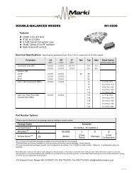
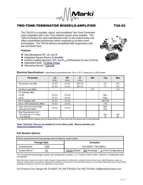
TWO-TONE-TERMINATOR MIXER/LO-AMPLIFIERT3A-<strong>03</strong>The T3A-<strong>03</strong> is a versatile, robust, and broadband Two-Tone-Terminator<strong>mixer</strong> integrated with a sub 10 ps risetime square wave <strong>amplifier</strong>. TheT3A-<strong>03</strong> emp<strong>lo</strong>ys the most sophisticated <strong>mixer</strong> on the market today andoffers unparalleled performance when compared to all other <strong>mixer</strong>techno<strong>lo</strong>gies. The T3A-<strong>03</strong> delivers exceptional IMD suppression with<strong>lo</strong>w conversion <strong>lo</strong>ss.Features Ultra-Broadband RF, LO, and IF Integrated Square-Wave LO Amplifier Industry Leading Spurious, IP3, and P 1dB Performance for <strong>lo</strong>w LO Drive Application Note: T3 Mixer Primer Alternative Device: T3A3-08Electrical Specifications - Specifications guaranteed from -30 to +70C, measured in a 50Ω system.Parameter LO RF IF Min Typ Max(GHz) (GHz) (GHz)Conversion Loss (dB) .01-3.4 .01-3.4 .001-0.5 6.5 8.0.01-3.4 .01-3.4 .001-3.4 7.0 9.5LO Drive Level (dBm) +10 +15LO Leakage (dBm)LO-RF .01-3.4 .01-3.4 SeeLO-IF .01-3.4 .01-3.4 P<strong>lo</strong>tsRF-IF Isolation (dB) .01-3.4 .01-3.4 See P<strong>lo</strong>tInput 1 dB Compression (dBm) .01-3.4 .01-3.4 +16Input Two-Tone Third OrderIntercept Point (dBm).01-3.4 .01-3.4Bias Requirements (mA) 1+5.0 Volts DC (+7 V max)-5.0 Volts DC1 It is required that the negative bias be applied before or concurrent with the positive bias to avoid damage.SeeP<strong>lo</strong>t2001025020*Note: EZ-Carrier T3As are not suitable for in-line ref<strong>lo</strong>w solder. Manual assembly only.(Refer to EZ Installation Notes).Part Number OptionsPlease specify diode level and package style by adding to model number.Package StyleExamplesConnectorized EZP T3A-<strong>03</strong>EZP, T3A-<strong>03</strong>EZ-2Surface Mount 1 EZ T3A-<strong>03</strong> (Model) EZP (Package) -2 (I-Port Configuration)1 For non-connectorized packages, specify I-port configuration by adding –1 or –2 suffix to model number. Default is –2 configuration whennot specified.<strong>Marki</strong> <strong>Microwave</strong> reserves the right to make changes to the product(s) or information contained herein without notice. <strong>Marki</strong> <strong>Microwave</strong> makes nowarranty, representation or guarantee regarding the suitability of its products for any particular purpose, nor does <strong>Marki</strong> <strong>Microwave</strong> assume any liabilitywhatsoever arising out of the use of or application of any product.215 Vineyard Court, Morgan Hill, CA 95<strong>03</strong>7 | Ph: 408.778.4200 | Fax 408.778.4300 | info@markimicrowave.com4/25/13
TWO-TONE-TERMINATOR MIXER/LO AMPLIFIERT3A-<strong>03</strong>Page 2LO/RF 10 MHz to 3.4 GHzIF 1 MHz to 3.4 GHz-5Typical Performance35Input IP3 (dBm)-730-9-1125-13-15Conversion Loss (dB) 1-3 150 0.5 1 1.5 2 2.5 3 3.520+10 dBm Sine Wave+15 dBm Sine Wave0 0.5 1 1.5 2 2.5 3 3.5RF Frequency (GHz)RF Frequency (GHz)0Relative IF Response (dB)0Low-End Relative IF Response (dB)-1-1-2-2-3-3-4-4-5-5-60 0.5 1 1.5 2 2.5 3 3.5-60 0.1 0.2 0.3 0.4 0.5 0.6 0.7 0.8 0.9 1IF Frequency (GHz)IF Frequency (MHz)5RF VSWR5LO VSWR44332210 0.5 1 1.5 2 2.5 3 3.510 0.5 1 1.5 2 2.5 3 3.5RF Frequency (GHz)LO Frequency (GHz)0RF to IF Isolation (dB)5IF VSWR-104-20-3<strong>03</strong>-402-500 0.5 1 1.5 2 2.5 3 3.5RF Frequency (GHz)10 0.5 1 1.5 2 2.5 3 3.5IF Frequency (GHz)4/25/13
TWO-TONE-TERMINATOR MIXERPage 3T3A-<strong>03</strong>LO/RF 10 MHz to 3.4 GHzIF 1 MHz to 3.4 GHzTypical Performance10LO to RF Leakage (dBm)10LO to IF Leakage (dBm)00-10-10-20-20-30-30-400 0.5 1 1.5 2 2.5 3 3.5-400 0.5 1 1.5 2 2.5 3 3.5LO Frequency (GHz)LO Frequency (GHz)0LO Even Harmonic to RF Leakage (dBm)0LO Even Harmonic to IF Leakage (dBm)-10-10-20-20-30-30-40-40-50-50-60-70-802xLO to RF4xLO to RF0 0.5 1 1.5 2 2.5 3 3.5-60-70-802xLO to IF4xLO to IF0 0.5 1 1.5 2 2.5 3 3.5LO Output Frequency (GHz)LO Output Frequency (GHz)0LO Odd Harmonic to RF Leakage (dBm)0LO Odd Harmonic to IF Leakage (dBm)-10-10-20-20-30-30-40-40-50-50-60-70-8<strong>03</strong>xLO to RF5xLO to RF0 0.5 1 1.5 2 2.5 3 3.5-60-70-8<strong>03</strong>xLO to IF5xLO to IF0 0.5 1 1.5 2 2.5 3 3.5LO Output Frequency (GHz)LO Output Frequency (GHz)4/25/13
TWO-TONE-TERMINATOR MIXERPage 4T3A-<strong>03</strong>LO/RF 10 MHz to 3.4 GHzIF 1 MHz to 3.4 GHzDownconversion Spurious SuppressionSpurious data is taken by selecting RF and LO frequencies (+mLO+nRF) within the 10 MHz to 3.4 GHz RF/LO bands,which create a 100 MHz IF spurious output. The <strong>mixer</strong> is swept across the full spurious band and the mean iscalculated. The numbers shown in the table be<strong>lo</strong>w are for a -10 dBm RF input. Spurious suppression is scaled fordifferent RF power levels by (n-1), where “n” is the RF spur order. For example, the 2RFx2LO spur is 69 dBc for a -10dBm input, so a -20 dBm RF input creates a spur that is (2-1) x (-10 dB) dB <strong>lo</strong>wer, or 79 dBc.Typical Downconversion Spurious Suppression (dBc): +10 (+15) dBm Sine Wave LO-10 dBm RF Input 0xLO 1xLO 2xLO 3xLO 4xLO 5xLO0xRF ------------- See LO to IF Isolation and LO Harmonic to IF Isolation P<strong>lo</strong>ts (Page 3)1xRF 20 (27) Reference 29 (29) 10 (10) 38 (30) 16 (16)2xRF 70 (70) 71 (75) 71 (73) 72 (79) 68 (71) 70 (80)3xRF 100 (100) 90 (97) 93 (94) 74 (88) 93 (96) 78 (83)4xRF >110 >110 >110 >110 >110 >1105xRF >120 >120 >120 >120 >120 >120A sample downconversion spurious sweep is shown be<strong>lo</strong>w. An LO 100 MHz higher than the RF is used to create a 100MHz reference IF. A second LO is used to create a 2x2 spurious IF, also at 100 MHz (50 MHz fundamental IF). Thedifference between these <strong>two</strong> output levels is the spurious suppression in dBc. The mean value across the full 10 MHzto 3.4 GHz RF input band is the number shown in the table above.0-10-20-30-40-50-60-70-80-902RF x 2LO Spurious Suppression (dBc)+10 dBm Sine Wave+15 dBm Sine Wave0 0.5 1 1.5 2 2.5 3 3.5RF Input Frequency (GHz)Downconversion 2RFx2LOSpurious Data Example:RF Input: 10 MHz to 3.4 GHz @ -10 dBmLO for Reference: 110 MHz to 3.5 GHzLO for Spurious: 60 MHz to 3.45 GHzIF Output: 100 MHz4/25/13
TWO-TONE-TERMINATOR MIXERPage 5T3A-<strong>03</strong>LO/RF 10 MHz to 3.4 GHzIF 1 MHz to 3.4 GHzUpconversion Spurious SuppressionSpurious data is taken by mixing a 100 MHz IF with LO frequencies (+mLO+nIF), which creates an RF within the 10 MHzto 7 GHz RF band. The <strong>mixer</strong> is swept across the full spurious output band and the mean is calculated. The numbersshown in the table be<strong>lo</strong>w are for a -10 dBm IF input. Spurious suppression is scaled for different IF input power levels by(n-1), where “n” is the IF spur order. For example, the 2IFx1LO spur is typically 69 dBc for a -10 dBm input, so a -20dBm IF input creates a spur that is (2-1) x (-10 dB) dB <strong>lo</strong>wer, or 79 dBc.Typical Upconversion Spurious Suppression (dBc): +10 (+15) dBm Sine Wave LO-10 dBm RF Input 0xLO 1xLO 2xLO 3xLO 4xLO 5xLO0xIF ------------- See LO to RF Isolation and LO Harmonic to RF Isolation P<strong>lo</strong>ts (Page 3)1xIF 20 (25) Reference 28 (30) 10 (10) 37 (28) 17 (17)2xIF 71 (70) 68 (72) 72 (80) 70 (66) 70 (80) 65 (67)3xIF 96 (106) 91 (98) 97 (96) 93 (93) 95 (100) 80 (91)4xIF >110 >110 >110 >110 >110 >1105xIF >120 >120 >120 >120 >120 >120A sample upconversion spurious sweep is shown be<strong>lo</strong>w. A 100 MHz reference IF input is used to create an RF outputthat is 100 MHz be<strong>lo</strong>w the LO input (LO-IF=RF). A second LO (100 MHz higher) is combined with the same 100 MHz IFinput (LO-2xIF=RF) to create the same 10 MHz to 3.4 GHz RF output band. The difference between these <strong>two</strong> outputlevels is the spurious suppression in dBc. The mean value across the full RF output band is the number shown in thetable above.0-10-20-30-40-50-60-70-80-902IF x 1LO Spurious Suppression (dBc)+10 dBm Sine Wave+15 dBm Sine Wave0 0.5 1 1.5 2 2.5 3 3.5RF Output Frequency (GHz)Upconversion 2IF x 1LOSpurious Data Example:IF Input: 100 MHz @ -10 dBmLO for Reference: 110 MHz to 3.5 GHzLO for Spurious: 210 MHz to 3.6 GHzRF Output: 10 MHz to 3.4 GHz4/25/13
TWO-TONE-TERMINATOR MIXERPage 6T3A-<strong>03</strong>LO/RF 10 MHz to 3.4 GHzIF 1 MHz to 3.4 GHzSine WaveSquare WaveT3LOAmplifierLIRRF-V+VIFPort Description DC Interface SchematicLOThe LO port is DC b<strong>lo</strong>cked and AC matched to 50 Ohms from 10 MHzto 3.4 GHz.LO 1 uFRFThe RF port is DC short to ground and AC matched to 50 Ohms from10 MHz to 3.4 GHz. B<strong>lo</strong>cking capacitor is optional.RFIFThe IF port is DC b<strong>lo</strong>cked and AC matched to 50 Ohms from 1 MHz to3.4 GHz.IF 2 uFAbsolute Maximum RatingsParameterMaximum RatingRF DC Current1 AmpLO DC Current1 AmpRF Power Handling+25 dBmLO Power Handling+17 dBmOperating Temperature-30ºC to +70ºCStorage Temperature-65ºC to +125ºCESD Sensitivity (HBM) Class 0DATA SHEET NOTES:1. Mixer Conversion Loss P<strong>lo</strong>t IF frequency is 100 MHz.2. Mixer Noise Figure typically measures within 0.5 dB of conversion <strong>lo</strong>ss for IF frequencies greater than 5 MHz.3. Conversion Loss typically degrades less than 0.5 dB at +100°C and improves less than 0.5 dB at -55°C.4. Specifications are subject to change without notice. Contact <strong>Marki</strong> <strong>Microwave</strong> for the most recent specifications and data sheets.5. Cata<strong>lo</strong>g <strong>mixer</strong> circuits are continually improved. Configuration control requires custom <strong>mixer</strong> model numbers and specifications.<strong>Marki</strong> <strong>Microwave</strong> reserves the right to make changes to the product(s) or information contained herein without notice. <strong>Marki</strong> <strong>Microwave</strong> makes nowarranty, representation, or guarantee regarding the suitability of its products for any particular purpose, nor does <strong>Marki</strong> <strong>Microwave</strong> assume anyliability whatsoever arising out of the use or application of any product.© <strong>Marki</strong> <strong>Microwave</strong>, Inc.215 Vineyard Court, Morgan Hill, CA 95<strong>03</strong>7 | Ph: 408.778.4200 | Fax 408.778.4300 | info@markimicrowave.comwww.markimicrowave.com4/25/13