Projectile Motion Report A.pdf
Projectile Motion Report A.pdf
Projectile Motion Report A.pdf

You also want an ePaper? Increase the reach of your titles
YUMPU automatically turns print PDFs into web optimized ePapers that Google loves.
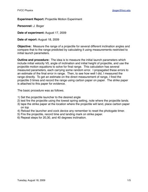
FVCC Physicsjboger@fvcc.eduExperiment <strong>Report</strong>: <strong>Projectile</strong> <strong>Motion</strong> ExperimentPersonnel: J. BogerDate of experiment: August 17, 2009Date of report: August 18, 2009Objective: Measure the range of a projectile for several different inclination angles andcompare that to the range predicted by calculating it using measurements restricted toinitial launch parameters.Outline and procedure: The idea is to measure the initial launch parameters whichinclude initial velocity V0, angle of inclination and initial height of projectile, and use theprojectile motion equations to solve for final range. This calculation has severalmeasured parameters, each carrying some random error. I propagated these errors toan estimate of the final error in range. Then, to see how well I did, I measured therange directly. To get an estimate on the direct measurement of range, I fired theprojectile 3 times and record the range using carbon paper on paper. The strike paperis attached to this paper for evidence.The basic procedure was as follows.1) Set the projectile launcher to the desired angle2) test fire the projectile using the lowest spring setting, note where the projectile lands.3) tape the strike paper at the location where the projectile will land, place carbon paperon top4) Reload the launcher and cock device any remember to reset the photogate timer.5) Fire the projectile, record time and landing mark on strike paper.6) Repeat steps for 20,30, and 40 degrees inclination.Tuesday, August 18, 2009 1/5
FVCC Physicsjboger@fvcc.eduyv0θxFigure 1. <strong>Projectile</strong> rangeData table:See Spreadsheet <strong>Projectile</strong> motion Table 1CalculationsStarting with the equations for projectile motion:R Calc= x 0+ v 0 xt ofy = y 0+ v 0 yt of− 1 2 gt 2ofFrom which we can solve the y equation for time of flight, tof.t of= v 0 x ±v 20 xg+ 2gy 0Tuesday, August 18, 2009 2/5
FVCC Physicsjboger@fvcc.eduBy vector components, the velocity is found in x and y directions.v 0 x= v 0cosθv 0 y= v 0sinθThe initial velocity is found from the photogate time and separation and calculated by,v 0= L t LHere tL is the time it takes the projectile to go from one gate to another. With tofcalculated, we can calculate range.R Calc= v 0 xt ofError Calculations:I propagated the errors from measurements to Rcalc. Here is the principle errorpropagation formula for this.ΔR Calc= R Calc⎛⎝⎜Δv 0 xv 0 x⎞⎠⎟Where the error in tof is:2⎛+ Δt ⎞of⎜ ⎟⎝ ⎠t of2⎛⎜⎝Δt oft of⎞⎟⎠2=2v 0 y1 ⎛ Δy 2 ⎞2+ Δv2 0 y+ 2gy⎜ ⎟0 ⎝ ⎠t ofand the error in v0x is:Δv 0 xv 0 x=⎛⎝⎜ΔLL⎞⎠⎟2⎛ Δθ sinθ ⎞+⎝⎜cosθ ⎠⎟2This all comes from propagating errors in an algebraic formula. Unfortunately the errorsare complicated due to a complicated formula used to process data.Tuesday, August 18, 2009 3/5
FVCC Physicsjboger@fvcc.eduResults:Comparing measured and calculated ranges1.3001.175Range (m)1.0500.9250.8000 10 20 30 40Inclination angleRange CalculatedRange MeasuredPlot of Range as measured and as calculated. Errors overlap for 10 and 30 degreeinclination data, but not for 20 and 40 degrees. I calculated accuracy of the data byassuming my measured value was truth. With that, the following accuracies wherefound.Accuracy atinclinations10203040Accuracy3.9613.21.543.54Table 1. Accuracy in experiment.The % accuracy matches the plot in that those value which overlap have a generallylower error.Clearly the methods compare but I have made more error than is accounted for in mydata. I suspect that the distances in truth have more error in them than I have allowedTuesday, August 18, 2009 4/5
FVCC Physicsjboger@fvcc.edufor. Upon repeating the experiment, I would repeat the measurement of time betweenphotogates and find an error in this time value. I noted during data collection that thisvalue did vary and yet I considered it exact. In particular, I donʼt believe my value for t inthe 20 degree inclination data is correct. I adjusted this data value in the spreadsheetonly to observe the effect and found that the plotted data point immediately jumped upto the expected value. This enforced my belief that the blunder is in this data point.(The original value for the tL data point is not altered in this report.) Repeating this onedata point could close the 13% error seen in my data. Outside of this data point, theresults are rather good showing the trend of Range with inclination. This lab wasincredible, I wish I could do it everyday of the week for a month!Additional sheets to this report:1) 3 pages lab notes2) Spreadsheet with calculations and dataTuesday, August 18, 2009 5/5