PHS Technical Data Catalog - Bay Port Valve & Fitting
PHS Technical Data Catalog - Bay Port Valve & Fitting
PHS Technical Data Catalog - Bay Port Valve & Fitting
- No tags were found...

You also want an ePaper? Increase the reach of your titles
YUMPU automatically turns print PDFs into web optimized ePapers that Google loves.
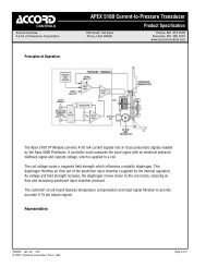
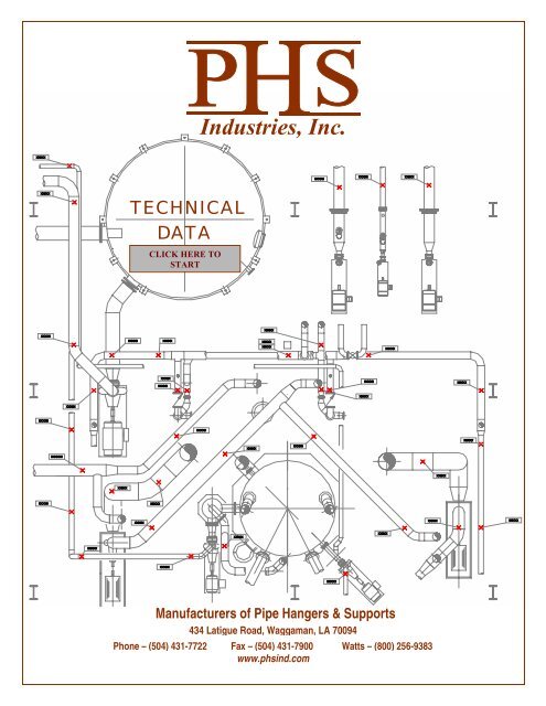
Industries, Inc.TECHNICALDATACLICK HERE TOSTARTManufacturers of Pipe Hangers & Supports434 Latigue Road, Waggaman, LA 70094Phone – (504) 431-7722 Fax – (504) 431-7900 Watts – (800) 256-9383www.phsind.com
<strong>PHS</strong> Industries, Inc. Phone: (504) 431-7722 Fax: (504) 431-7900 Watts: (800) 256-9383TABLE OF CONTENTSSimply click on the subject to go to the appropriate pageREFERENCE DATA – METRIC CONVERSION CHARTPIPE WEIGHTS FOR STANDARD AND HEAVY WEIGHT PIPEAMERICAN WATER WORKS ASSOCIATION - DUCTILE IRON PIPE DATACAST IRON PIPE DATANO-HUB CAST IRON PIPE DATADECIMAL EQUIVALENTSELECTRICAL CONDUIT SIZESC-CLAMP SET SCREW TORQUECOPPER TUBING DATA - TYPE LCOPPER TUBING DATA - TYPE KPIPE WEIGHTS FOR PVC AND CPVC PIPE – TYPES I & IIUSEFUL WEIGHT FORMULASCALCULATING OF PIPING INSULATION WEIGHTMAXIMUM HORIZONTAL HANGER SPACINGLOAD CHART FOR THREADED RODGAUGE THICKNESSHANGER SPACING FOR PVC AND CPVC PIPINGTHERMAL EXPANSION OF PIPE MATERIALSCOMMON STRUCTURAL SHAPES USED FOR PIPE SUPPORTSBASIC WELDING SYMBOLSCOMPONENT COMMON TYPES, MSS-SP-69 / WW-H-171TECHANICAL DATA /eRevision 0-ii-
<strong>PHS</strong> Industries, Inc. Phone: (504) 431-7722 Fax: (504) 431-7900 Watts: (800) 256-9383TECHNICAL INFORMATIONREFERENCE DATA – METRIC CONVERSION CHARTTO CONVERT FROM TO MULTIPLY BYAngle degree radian (rad) 1.745329 x 10 -2radian (rad) degree 5.729578 x 10 +1Area foot 2 square meter (m 2 ) 9.290304 x 10 -2inch 2 square meter (m 2 ) 6.451600 x 10 -4circular mil square meter (m 2 ) 5,067075 x 10 -10square centimeter (cm 2 ) square inch (in 2 ) 1.550003 x 10 -1square meter (m 2 ) foot 2 1.076391 x 10 +1square meter (m 2 ) inch 2 1.550003 x 10 +3square meter (m 2 ) circular mil 1.973525 x 10 +9Bending lbf•ft newton meter (N•m) 1.355818Moment of lbf•in newton meter (N•m) 1.129848 x 10 -1Torque N•m lbf•ft 7.375621 x 10 -1N•m lbf•in 8.850748Force pounds-force (lbf) newtons (N) 4.448222Length foot (ft) meter (m) 3.048000 x 10 -1inch (in) meter (m) 2.540000 x 10 -2mil meter (m) 2.540000 x 10 -5inch (in) micrometer (µm) 2.540000 X 10 +4meter (m) foot (ft) 3.280840meter (m) inch (in) 3.937008 x 10 +1meter (m) mil 3.937008 x 10 +4micrometer (µm) Inch (in) 3.937008 x 10 -5Mass ounce (avoirdupois) kilogram (kg) 2.834952 x 10 -2pound (avoirdupois) kilogram (kg) 4.535924 x 10 -1on (short, 2000 lb) kilogram (kg) 9.071847 x 10 +2on (long, 2240 lb) kilogram (kg) 1.016047 x 10 +3kilogram (kg) ounce (avoirdupois) 3.527396 x 10 +1kilogram (kg) pound (avoirdupois) 2.204622kilogram (kg) ton (short 2000 lb) 1.102311 x 10 -3kilogram (kg) ton (long 2240 lb) 9.842064 x 10 -4Mass Per lb/ft kilogram per meter (kg/m) 1.488164Unit Length lb/in kilogram per meter (kg/m) 1.785797 x 10 +1kg/m lb/ft 6.719689 x 10 -1kg/m lb/in 5.599741 x 10 -2Mass Per lb/ft 3 kilogram per cubic meter (kg/m 3 ) 1.601846 x 10 -1Unit Volume lb/in 3 kilogram per cubic meter (kg/m 3 ) 2.767990 x 10 +4kg/m 3 lb/ft 3 6.242797 x 10 -2kg/m 3 lb/in 3 3 612730 x 10 -5lbs/ft 3 lbs/in 3 1.728000 x 10 +3Mass Per lb/ft 2 kilogram per square meter (kg/m 2 ) 4882428Area Unit kg/m 2 pound per square foot (lb/ft 2 ) 2.048161 x 10 -1Pressure or lbf/in 2 (psi) pascal (Pa) 6.894757 x 10 +3Stress kip/in 2 (ksi) pascal (Pa) 6-894757 x 10 +6lbf/in 2 (psi) megapascals (MPa) 6.894757 x 10 -3pascal (Pa) pound force per sq. inch (psi) 1.450377 x 10 -4pascal (Pa) kip per sq. inch (ksi) 1.450377 x 10 -7megapascals (MPa) lbf/in 2 (psi) 1-450377 x 10 +2Section section modulus S (in 3 ) S (m 3 ) 1.638706 x 10 -5Properties section modulus S (M 3 ) S (in 3 ) 6.102374 x 10 +4moment of inertia I (in 4 ) 1 (m 4 ) 4.162314 x 10 -7moment of inertia I (M 4 ) I (in 4 ) 2.402510 x 10 +6modulus of elasticity E (psi) E (Pa) 6.894757 x 10 +3modulus of elasticity E (Pa) E (psi) 1.450377 x 10 -4Temperature degree Fahrenheit degree Celsius t° C = t° F - 32) / 1.8degree Celsius degree Fahrenheit t° F = 1.8 t° C + 32Volume foot 3 cubic meter (m 3 ) 2.831685 x 10 -2inch 3 cubic meter (m 3 ) 1.638706 x 10 -2cubic centimeter (cm 3 ) cubic inch (in 3 ) 6.102374 x 10 -2cubic meter (m 3 ) foot 3 3.531466 x 10 +1cubic meter (m 3 ) inch 3 6.102376 x 10 +4gallon (U.S. liquid) cubic meter (m 3 ) 3.785412 x 10 -3ABBREVIATIONSAISC = American Institute ofSteel ConstructionAISI = American Iron & SteelInstituteANSI = American NationalStandards InstituteASTM = American Society forTesting & MaterialsAWWA = American Water WorksAssociationDia. = DiameterFt. = FeetGa = GaugeI.D. = Inside DiameterIn. = InchLbs. = PoundsMax. = MaximumMin. = MinimumMSS = Manufacturers'Standardization SocietyNFPA = National Fire ProtectionAssociationO.D. = Outside DiameterOz. = Ouncespsi = Pounds Per Square InchPVC = Poly Vinyl ChlorideUNC = Unified Course ThreadsUNCR = Unified Course Threads(Rounded Root)METRIC SYMBOLScm = centimeterkg = kilogramkN = kilonewtonm = meterµm = micrometermm = millimeterMPa = megapascalN = newtonNm = newton-meterPa = pascal-1-
<strong>PHS</strong> Industries, Inc. Phone: (504) 431-7722 Fax: (504) 431-7900 Watts: (800) 256-9383TECHNICAL INFORMATIONPIPE WEIGHTS FOR STANDARD AND HEAVY WEIGHT PIPEPIPE DATAPIPE WEIGHTNominal Pipe Outside Dia. Wall Th’k w/ Gas, Air, Steam w/ WaterPipe Size Schedule in mm in lbs/ft N/m lbs/ft N/m1⁄2" Std / 40 0.840 22 0.109 0.9 12 1.0 14(15mm) XS / 80 0.147 1.1 16 1.2 173⁄4" Std / 40 1.050 28 0.113 1.1 17 1.4 20(20mm) XS / 80 0.154 1.5 22 1.7 241" Std / 40 1.315 34 0.133 1.7 25 2.1 30(25mm) XS / 80 0.179 2.2 32 2.5 361 1 ⁄4" Std / 40 1.660 42 0.140 2.3 33 2.9 43(32mm) XS / 80 0.191 3.0 44 3.6 521 1 ⁄2" Std / 40 1.900 48 0.145 2.7 40 3.6 53(40mm) XS / 80 0.200 3.6 53 4.4 642" Std / 40 2.375 60 0.154 3.7 53 5.1 75(50mm) XS / 80 0.218 5.0 73 6.3 922 1 ⁄2" Std / 40 2.875 75 0.203 5.8 85 7.9 115(65mm) XS / 80 0.276 7.7 112 9.5 1393" Std / 40 3.500 89 0.216 7.6 111 11 157(80mm) XS / 80 0.300 10 150 13 1913 1 ⁄2" Std / 40 4.000 102 0.226 9.1 133 13 195(90mm) XS / 80 0.318 13 182 16 2394" Std / 40 4.500 114 0.237 11 157 16 238(100mm) XS / 80 0.337 15 219 20 2915" Std / 40 5.563 141 0.258 15 213 23 340(125mm) XS / 80 0.375 21 303 29 4186" Std / 40 6.625 168 0.280 19 277 31 460(150mm) XS / 80 0.432 29 417 40 5828" Std / 40 8.625 219 0.322 29 417 50 733(200mm) XS / 80 0.500 43 633 63 92210" Std / 40 10.75 273 0.365 40 591 75 1090(250mm) XS / 60 0.500 55 799 87 127112" Std 12.75 235 0.375 50 723 99 1439(300mm) XS 0.500 65 955 112 164114" Std / 30 14.00 355.6 0.375 55 796 114 1669(350mm) XS 0.500 72 1052 130 189216" Std / 30 16.00 406.4 0.375 63 913 142 2069(400mm) XS / 40 0.500 83 1208 159 232618" Std 18.00 457.2 0.375 71 1030 172 2509(450mm) XS 0.500 93 1364 192 280020" Std / 20 20.00 508.0 0.375 79 1147 205 2988(500mm) XS / 30 0.500 104 1520 227 331324" Std / 20 24.00 609.6 0.375 95 1381 279 4067(600mm) XS 0.500 125 1831 306 446030" Std 30.00 762.0 0.375 119 1731 410 5983(750mm) XS / 20 0.500 158 2299 444 647836" Std 36.00 914.4 0.375 143 2082 566 8256(900mm) XS / 20 0.500 190 2766 607 885342" Std 42.00 1066.8 0.375 167 2433 746 10888(1050mm) XS / 20 0.500 222 3234 794 11587Pipe Weights are based on Carbon Steel pipe-2-
<strong>PHS</strong> Industries, Inc. Phone: (504) 431-7722 Fax: (504) 431-7900 Watts: (800) 256-9383TECHNICAL INFORMATIONAMERICAN WATER WORKS ASSOCIATION - DUCTILE IRON PIPE DATABASED UPON AWWA C108-70 CLASS 53NOMINALWEIGHT OF PIPEPIPE SIZE O.D. SIZE WALL THICKNESS WEIGHT OF PIPE FILLED WITH WATERin. mm in. mm in. mm Lbs./Ft. Kg/m Lbs./Ft. Kg/m3 80 3.96 100.6 0.31 7.9 11.2 16.7 15.0 22.34 100 4.80 121.9 0.32 8.1 14.2 21.1 20.1 29.96 150 6.90 175.3 0.34 8.6 22.0 32.7 35.1 52.28 200 9.05 229.9 0.36 9.1 31.0 46.1 54.0 80.410 250 11.1 281.9 0.38 9.7 40.4 60.1 76.8 114.312 300 13.2 335.3 0.40 10.2 50.7 75.5 103.0 153.314 350 15.3 388.6 0.42 10.7 62.4 92.9 133.5 198.716 400 17.4 442.0 0.43 10.9 72.8 108.3 165.9 246.918 450 19.5 495.3 0.44 11.2 83.6 124.4 201.5 299.920 500 21.6 548.6 0.45 11.4 95.2 141.7 241.0 358.724 600 25.8 655.3 0.47 11.9 119.2 177.4 329.4 490.230 750 32.0 812.8 0.51 13.0 161.3 240.0 487.8 725.936 900 38.3 972.8 0.58 14.7 219.5 326.7 688.8 1025.142 1050 44.5 1130.3 0.65 16.5 285.2 424.4 920.1 1369.348 1200 50.8 1290.3 0.72 18.3 360.3 536.2 1189.2 1769.854 1350 57.1 1450.3 0.81 20.6 455.0 677.1 1502.2 2235.6Note: Add flange weight for flanged ductile iron pipeCAST IRON PIPE DATAMECHANICAL JOINT PIPE CLASS 150NOMINALWEIGHT OF PIPEPIPE SIZE O.D. SIZE WALL THICKNESS WEIGHT OF PIPE FILLED WITH WATERin. mm in. mm in. mm Lbs./Ft. Kg/m Lbs./Ft. Kg/m3 80 3.96 100.6 0.32 8.1 12.9 19.2 16.6 24.74 100 4.80 121.9 0.35 8.9 16.4 24.4 22.1 32.96 150 6.90 175.3 0.38 9.7 25.7 38.2 38.5 57.38 200 9.05 229.9 0.41 10.4 36.7 54.6 59.8 89.010 250 11.1 281.9 0.44 11.2 48.7 72.5 84.2 125.312 300 13.2 335.3 0.48 12.2 62.9 93.6 113.9 169.514 350 15.3 388.6 0.51 13.0 78.8 117.3 148.1 220.416 400 17.4 442.0 0.54 13.7 95.0 141.4 185.3 275.818 450 19.5 495.3 0.58 14.7 114.7 170.7 228.7 340.420 500 21.6 548.6 0.62 15.7 135.9 202.2 277.4 412.824 600 25.8 655.3 0.73 18.5 190.4 283.4 391.4 582.530 750 32.0 812.8 0.85 21.6 277.3 412.7 589.3 877.036 900 38.3 972.8 0.94 23.9 368.9 549.0 817.9 1217.242 1050 44.5 1130.3 1.05 26.7 479.1 713.0 1091.1 1623.848 1200 50.8 1290.3 1.14 29.0 595.2 885.8 1398.2 2080.8Note: Add flange weight for flanged cast iron pipeINCHES FAHRENHEIT POUNDS POUNDSMILLIMETERS CELSIUS NEWTONS KILOGRAMS-3-
<strong>PHS</strong> Industries, Inc. Phone: (504) 431-7722 Fax: (504) 431-7900 Watts: (800) 256-9383TECHNICAL INFORMATIONNO-HUB CAST IRON PIPE DATABASED UPON CAST IRON SOIL PIPE INSTITUTE STANDARDS 301-72, TABLE 1NOMINALWEIGHT OF PIPEPIPE SIZE: O.D. SIZE WALL THICKNESS WEIGHT OF PIPE FILLED W/WATERin. mm in. mm in. mm Lbs./Ft. Kg/m Lbs./Ft. Kg/m1 1 ⁄2" 40 1.9 48.3 0.16 4.1 2.7 4.0 6.2 9.2 3.732" 50 2.35 59.7 0.16 4.1 3.6 5.4 8.6 12.8 5.723" 80 3.35 85.1 0.16 4.1 5.2 7.7 13.5 20.1 12.804" 100 4.38 111.3 0.19 4.8 7.4 11.0 20.2 30.1 23.105" 125 5.30 134.6 0.19 4.8 9.6 14.3 27.5 40.9 35.506" 150 6.30 160.0 0.19 4.8 11.0 16.4 34.0 50.6 51.008" 200 8.38 212.9 0.23 5.8 18.0 26.8 57.5 85.6 69.30DECIMAL EQUIVALENTSDECIMALS OF AN INCH & EQUIVALENT MILLIMETERSFRACTION DECIMAL MM FRACTION DECIMAL MM FRACTION DECIMAL MM FRACTION DECIMAL MM1⁄32 0.0313 0.794 9⁄32 0.2813 7.14417⁄32 0.5313 13.49425⁄32 0.7813 19.8441⁄16 0.0625 1.588 5⁄16 0.3125 7.938 9⁄16 0.5625 14.28813⁄16 0.8125 20.6383⁄32 0.0938 2.38111⁄32 0.3438 8.73119⁄32 0.5938 15.08127⁄32 0.8438 21.4311⁄8 0.1250 3.175 3⁄8 0.3750 9.525 5⁄8 0.6250 15.875 7⁄8 0.8750 22.2255⁄32 0.1563 3.96913⁄32 0.4063 10.31921⁄32 0.6563 16.66929⁄32 0.9063 23.0193⁄16 0.1875 4.763 7⁄16 0.4375 11.11311⁄16 0.6875 17.46315⁄16 0.9375 23.8137⁄32 0.2188 5.55615⁄32 0.4688 11.90623⁄32 0.7188 18.25631⁄32 0.9688 24.6061⁄4 0.2500 6.350 1⁄2 0.5000 12.700 3⁄4 0.7500 19.050 1 1.0000 25.400ELECTRICAL CONDUIT SIZESNOMINAL ELECTRICAL METALLIC INTERMEDIATE METALLIC STEEL RIGIDCONDUIT SIZE CONDUIT O.D. CONDUIT O.D. CONDUIT O.D.1⁄2 0.706 0.815 0.8403⁄4 0.922 1.029 1.0501 1.163 1.290 1.3151 1 ⁄4 1.510 1.638 1.6601 1 ⁄2 1.740 1.863 1.9002 2.197 2.360 2.3752 1 ⁄2 2.875 2.857 2.8753 3.500 3.476 3.5003 1 ⁄2 4.000 3.971 4.0004 4.500 4.466 4.5005 5.5636 6.625C-CLAMP SET SCREW TORQUEFOR SET SCREW IN MSS TYPE 19 AND 23 C-CLAMPS PER MSS-SP-69MAXIMUM TORQUE VALUESET SCREW SIZE INCH-POUNDS NEWTON-METERS1⁄4 M6 40 4.53⁄8 M10 60 6.81⁄2 M12 125 14.15⁄8 M16 250 28.23⁄4 M20 400 45.27⁄8 M20 665 75.1-4-
<strong>PHS</strong> Industries, Inc. Phone: (504) 431-7722 Fax: (504) 431-7900 Watts: (800) 256-9383TECHNICAL INFORMATIONCOPPER TUBING DATA - TYPE LNOMINALWEIGHT OF TUBINGTUBING SIZE O.D. SIZE WALL THICKNESS WEIGHT OF TUBING FILLED WITH WATERin. mm in. mm in. mm Lbs./Ft. Kg/m Lbs./Ft. Kg/m1⁄4 8 0.375 9.5 0.030 0.8 0.13 0.19 0.15 0.223⁄8 10 0.500 12.7 0.035 0.9 0.20 0.29 0.26 0.391/2 15 0.625 15.9 0.040 1.0 0.29 0.42 0.38 0.575⁄8 18 0.750 19.1 0.042 1.1 0.36 0.54 0.51 0.763⁄4 20 0.875 22.2 0.045 1.1 0.46 0.68 0.66 0.981 25 1.125 28.6 0.050 1.3 0.66 0.97 1.01 1.501 1 ⁄4 32 1.375 34.9 0.055 1.4 0.88 1.32 1.42 2.111 1 ⁄2 40 1.625 41.3 0.060 1.5 1.14 1.70 1.91 2.842 50 2.125 54.0 0.070 1.8 1.75 2.60 3.09 4.602 1 ⁄2 65 2.625 66.7 0.080 2.0 2.48 3.69 4.54 6.763 80 3.125 79.4 0.090 2.3 3.33 4.96 6.28 9.353 1 ⁄2 90 3.625 92.1 0.100 2.5 4.29 6.38 8.28 12.324 100 4.125 104.8 0.110 2.8 5.38 8.01 10.57 15.735 125 5.125 130.2 0.125 3.2 7.61 11.30 15.69 23.356 150 6.125 155.6 0.140 3.6 10.20 15.20 21.81 32.468 200 8.125 206.4 0.200 5.1 19.26 28.70 39.49 58.7710 250 10.125 257.2 0.250 6.4 20.10 29.90 61.69 91.8112 300 12.125 308.0 0.280 7.1 40.40 60.10 85.83 127.73COPPER TUBING DATA - TYPE KNOMINALWEIGHT OF TUBINGTUBING SIZE O.D. SIZE WALL THICKNESS WEIGHT OF TUBING FILLED WITH WATERin. mm in. mm in. mm Lbs./Ft. Kg/m Lbs./Ft. Kg/m1⁄4 8 0.375 9.5 0.035 0.9 0.14 0.21 0.17 0.253⁄8 10 0.500 12.7 0.049 1.2 0.27 0.40 0.32 0.481⁄2 15 0.625 15.9 0.049 1.2 0.34 0.51 0.43 0.645⁄8 18 0.750 19.1 0.049 1.2 0.42 0.63 0.56 0.833⁄4 20 0.875 22.2 0.065 1.7 0.64 0.95 0.83 1.241 25 1.125 28.6 0.065 1.7 0.84 1.25 1.18 1.761 1 ⁄4 32 1.375 34.9 0.065 1.7 1.04 1.55 1.57 2.341 1 ⁄2 40 1.625 41.3 0.072 1.8 1.36 2.02 2.10 3.132 50 2.125 54.0 0.083 2.1 2.06 3.07 3.37 5.022 1 ⁄2 65 2.625 66.7 0.095 2.4 2.92 4.35 4.92 7.323 80 3.125 79.4 0.109 2.8 4.00 5.95 6.96 10.363 1 ⁄2 90 3.625 92.1 0.120 3.0 5.12 7.62 9.02 13.424 100 4.125 104.8 0.134 3.4 6.51 9.69 11.57 17.225 125 5.125 130.2 0.160 4.1 9.67 14.4 17.67 26.306 150 6.125 155.6 0.192 4.9 13.87 20.6 25.07 37.318 200 8.125 206.4 0.271 6.9 25.90 38.5 45.40 67.5610 250 10.125 257.2 0.338 8.6 40.30 60.0 70.72 105.2512 300 12.125 308.0 0.405 10.3 57.80 86.0 101.48 151.02-5-
<strong>PHS</strong> Industries, Inc. Phone: (504) 431-7722 Fax: (504) 431-7900 Watts: (800) 256-9383TECHNICAL INFORMATIONPIPE WEIGHTS FOR PVC AND CPVC PIPE – TYPES I & IIPIPE DATA PVC PIPE WEIGHT CPVC PIPE WEIGHTNominal Pipe Outside Dia. Wall Th’k w/ Gas, Air w/ Water w/ Gas, Air w/ WaterPipe Size Schedule in mm in lbs/ft N/m lbs/ft N/m lbs/ft N/m lbs/ft N/m1⁄8" 40 0.405 10 0.068 0.05 0.7 0.07 1.0(3mm) 80 0.095 0.06 0.9 0.08 1.11⁄4" 40 0.54 14 0.088 0.08 1.2 0.13 1.9 0.09 1.3 0.13 2.0(6mm) 80 0.119 0.10 1.5 0.13 2.0 0.12 1.7 0.14 2.13⁄8" 40 0.675 17 0.091 0.11 1.6 0.19 2.8 0.12 1.8 0.20 3.0(10mm) 80 0.126 0.14 2.1 0.20 3.0 0.16 2.3 0.22 3.21⁄2" 40 0.840 22 0.109 0.17 2.4 0.30 4.4 0.19 2.7 0.31 4.6(15mm) 80 0.147 0.21 3.1 0.31 4.6 0.24 3.5 0.33 4.8120 0.170 0.24 3.4 0.32 4.73⁄4" 40 1.050 28 0.113 0.22 3.2 0.45 6.6 0.25 3.6 0.47 6.9(20mm) 80 0.154 0.29 4.2 0.47 6.9 0.32 4.7 0.50 7.3120 0.170 0.31 4.5 0.48 7.01" 40 1.315 34 0.133 0.33 4.8 0.70 10 0.37 5.4 0.73 11(25mm) 80 0.179 0.42 6.2 0.74 11 0.47 6.9 0.77 11120 0.200 0.46 6.8 0.75 111 1 ⁄4" 40 1.660 42 0.140 0.44 6.5 1.1 16 0.50 7.2 1.1 16(32mm) 80 0.191 0.58 8.5 1.1 17 0.65 9.5 1.2 17120 0.215 0.65 9.5 1.2 171 1 ⁄2" 40 1.900 48 0.145 0.53 7.8 1.4 21 0.60 8.7 1.5 21(40mm) 80 0.200 0.71 10 1.5 22 0.79 12 1.5 22120 0.225 0.79 11 1.5 222" 40 2.375 60 0.154 0.72 10 2.2 32 0.80 12 2.2 33(50mm) 80 0.218 0.98 14 2.3 33 1.1 16 2.3 34120 0.250 1.1 16 2.3 342 1 ⁄2" 40 2.875 75 0.203 1.1 17 3.2 47 1.3 18 3.3 48(65mm) 80 0.276 1.5 22 3.3 49 1.7 24 3.5 50120 0.300 1.6 24 3.4 493" 40 3.500 89 0.216 1.5 22 4.7 68 1.7 24 4.8 70(80mm) 80 0.300 2.0 29 4.9 71 2.2 33 5.0 73120 0.350 2.3 34 5.0 733 1 ⁄2" 40 4.000 102 0.226 1.8 26 6.1 89 2.0 29 6.2 91(90mm) 80 0.318 2.5 36 6.3 92 2.7 40 6.5 954" 40 4.500 114 0.237 2.1 31 7.6 111 2.4 34 7.8 114(100mm) 80 0.337 2.9 43 7.9 116 3.3 48 8.2 119120 0.437 3.7 54 8.2 1205" 40 5.563 141 0.258 2.9 42 12 168(125mm) 80 0.375 4.1 60 12 1756" 40 6.625 168 0.280 3.7 54 16 237 4.2 61 17 242(150mm) 80 0.432 5.6 82 17 247 6.3 91 17 253120 0.562 7.1 104 17 2548" 40 8.625 219 0.322 5.6 82 27 398 6.3 91 28 405(200mm) 80 0.500 8.5 124 28 413 9.5 139 29 42310" 40 10.75 273 0.365 8.0 116 42 615 8.9 130 43 624(250mm) 80 0.593 13 184 44 639 14 206 45 65412" 40 12.75 235 0.406 11 153 59 862 12 171 60 874(300mm) 80 0.687 17 254 61 897 19 283 63 91714" 40 14.00 355.6 0.437 12 182 71 1038(350mm) 80 0.750 21 304 74 108116" 40 16.00 406.4 0.500 16 238 93 1356(400mm) 80 0.843 27 391 97 140918" 40 18.00 457.2 0.562 22 328 119 1743(450mm) 80 0.937 34 489 122 178120" 40 20.00 508.0 0.593 27 388 147 2146(500mm) 80 1.031 42 618 152 221724" 40 24.00 609.6 0.687 37 542 211 3086(600mm) 80 1.218 60 879 219 3189PVC and CPVC pipe weights are based on the “average I.D.”-6-
<strong>PHS</strong> Industries, Inc. Phone: (504) 431-7722 Fax: (504) 431-7900 Watts: (800) 256-9383TECHNICAL INFORMATIONUSEFUL WEIGHT FORMULASPIPEWeight (lb/ft) = 10.68 x T x (D - T) x FPIPE CONTENTSWeight (lb/ft) = 0.3405 x G x (D - 2T) 2LEGENDD = Outside Diameter (inches)F = Material Weight FactorG = Specific Gravity of Pipe ContentsNormally 1.0 for water, 0 for air and steam.L = Length (inches)T = Pipe Wall, Plate, or Bar Thickness (inches)W = Width (inches)PLATE AND BARWeight (lb) = 0.2833 x T x W x L x FROUND RODWeight (lb/ft) = 2.67D 2MATERIAL WEIGHT FACTORSCarbon Steel & Cr-Mo ..................1.00Aluminum ......................................0.35Brass ...............................................1.12Cast lron .........................................0.91Copper ............................................1.14Ferritic stainless steel .....................0.95Austenitic stainless steel ................1.02Wrought iron ..................................0.98CALCULATING OF PIPING INSULATION WEIGHTThe weight per foot of insulation is calculated by using the weightfactor “X” from the table below and multiplying by the insulationdensity (lbs/cu-ft).EXAMPLE: A 16" pipe with 3 1 ⁄2" of insulation is found to have aweight factor of 1.49 (from table below). With an insulation density of11 lb/cu-ft, the calculation for insulation weight is 1.49 x 11 = 16.39INSULATION WEIGHT FACTOR – XNOMINALNOMINAL INSULATION THICKNESSPIPE SIZE 1" 1 1 ⁄2" 2" 2 1 ⁄2" 3" 3 1 ⁄2" 4" 4 1 ⁄2" 5" 5 1 ⁄2" 6"1 .057 .10 .16 .23 .31 .401 1 ⁄4 .051 .12 .15 .22 .30 .391 1 ⁄2 .066 .11 .21 .29 .38 .482 .080 .14 .21 .29 .37 .47 .592 1 ⁄2 .091 .19 .27 .36 .46 .58 .70 .833 .10 .17 .25 .34 .44 .56 .68 .813 1 ⁄2 .15 .23 .31 .41 .54 .66 .78 ... .974 .13 .21 .30 .39 .51 .63 .77 .96 1.105 .15 .24 .34 .45 .58 .71 .88 1.04 1.206 .17 .27 .38 .51 .64 .83 .97 1.13 1.348 .34 .47 .66 .80 .97 1.17 1.36 1.56 1.7510 .43 .59 .75 .93 1.12 1.32 1.54 1.76 1.9912 .50 .68 .88 1.07 1.28 1.52 1.74 1.99 2.24 2.5014 .51 .70 .90 1.11 1.34 1.57 1.81 2.07 2.34 2.6216 .57 .78 1.01 1.24 1.49 1.74 2.01 2.29 2.58 2.8818 .64 .87 1.12 1.37 1.64 1.92 2.21 2.51 2.82 3.1420 .70 .96 1.23 1.50 1.79 2.09 2.40 2.73 3.06 3.4024 .83 1.13 1.44 1.77 2.10 2.44 2.80 3.16 3.54 3.92General Formula: For pipe sizes not shown in the table above (specialO.D. pipe, etc.), use the following formula to determine the insulation weight:Insulation Weight: (lb/ft) = 0.0218 x I x T x (T + D)Where:I = Insulation density (lb/cu-ft)T = Insulation thickness (inches)D= Outside diameter of pipe (inches)-7-
<strong>PHS</strong> Industries, Inc. Phone: (504) 431-7722 Fax: (504) 431-7900 Watts: (800) 256-9383TECHNICAL INFORMATIONMAXIMUM HORIZONTALHANGER SPACINGPER MSS-SP69, AND ANSI B31.1NOMINAL STANDARD WEIGHTPIPE SIZE STEEL PIPE COPPER TUBINGOR SERVICE SERVICETUBE (FEET / METERS) (FEET / METERS)DIA. WATER VAPOR WATER VAPOR1⁄4 7 8 5 58 2.13 2.44 1.52 1.523⁄8 7 8 5 610 2.13 2.44 1.52 1.831⁄2 7 8 5 615 2.13 2.44 1.52 1.833⁄4 7 9 5 720 2.13 2.74 1.52 2.131 7 9 6 825 2.13 2.74 1.83 2.441 1 ⁄4 7 9 7 932 2.13 2.74 2.13 2.741 1 ⁄2 9 12 8 1040 2.74 3.66 2.44 3.052 10 13 8 1150 3.05 3.96 2.44 3.352 1 ⁄2 11 14 9 1365 3.35 4.27 2.74 3.963 12 15 10 1480 3.66 4.57 3.05 4.273 1 ⁄2 13 16 11 1590 3.96 4.88 3.35 4.574 14 17 12 16100 4.27 5.18 3.66 4.885 16 19 13 18125 4.88 5.79 3.96 5.496 17 21 14 20150 5.18 6.40 4.27 6.108 19 24 16 23200 5.79 7.32 4.88 7.0110 22 26 18 25250 6.71 7.92 5.49 7.6212 23 30 19 28300 7.01 9.14 5.79 8.5314 25 32350 7.62 9.7516 27 35400 8.23 10.6718 28 37450 8.53 11.2820 30 39500 9.14 11.8924 32 42600 9.75 12.8030 33 44750 10.06 13.41DIMENSIONS TEMPERATURE LOADS WEIGHTINCHES FAHRENHEIT POUNDS POUNDSMILLIMETERS CELSIUS NEWTONS KILOGRAMSLOAD CHART FOR THREADED RODMATERIALS: ASTM A36, A575 GR. 1020 OR A576 GR 1020MAXIMUMSAFE ROD LOAD WEIGHT ROOTNOMINAL ROD TEMPERATURE PER AREAROD 650°F 750°F FOOT IN. 2DIAMETER 349°C 399°C METER MM 21⁄4 240 210 0.167 0.027M6 1068 934 0.248 0.0173⁄8 610 540 0.360 0.068M10 2714 2402 0.536 0.0441⁄2 1130 1010 0.668 0.126M12 5027 4493 0.994 0.0815⁄8 1810 1610 1.04 0.202M16 8052 7162 1.55 0.1303⁄4 2710 2420 1.50 0.302M20 12055 10765 2.23 0.1957⁄8 3770 3360 2.04 0.419M20 16770 14947 3.04 0.2701 4960 4420 2.67 0.552M24 22064 19662 3.97 0.3561 1 ⁄4 8000 7140 3.38 0.889M30 35587 31762 5.03 0.5741 1 ⁄2 11630 10370 4.17 1.293M36 51735 46130 6.20 0.8341 3 ⁄4 15700 14000 6.01 1.744M42 69840 62278 8.94 1.1252 20700 18460 8.18 2.300M48 92082 82117 12.17 1.4842 1 ⁄4 27200 24260 10.68 3.023M56 120996 107918 15.89 1.9502 1 ⁄2 33500 29880 13.52 3.716M64 149021 132918 20.12 2.3982 3 ⁄4 41580 37066 16.69 4.619M72 184964 164884 24.83 2.9803 50580 45085 20.19 5.621M80 225000 200556 30.04 3.627GAUGE THICKNESSGAUGE MINIMUM NOMINAL3 0.215 0.2393 5.461 6.0717 0.167 0.1797 4.242 4.54711 0.108 0.12011 2.743 3.04812 0.093 0.10512 2.362 2.66713 0.080 0.09013 2.032 2.28614 0.066 0.07514 1.676 1.90516 0.053 0.06016 1.346 1.52418 0.042 0.04818 1.067 1.219-8-
<strong>PHS</strong> Industries, Inc. Phone: (504) 431-7722 Fax: (504) 431-7900 Watts: (800) 256-9383HANGER SPACING FOR PVC AND CPVC PIPINGPVCPipe 60° F 80° F 100° F 120° F 140° FSize Sch. ft mm ft mm ft mm ft mm ft mm1⁄2" 40 4.5 1.37 4.5 1.37 4.0 1.22 2.5 0.76 2.5 0.7615mm 80 5.0 1.52 4.5 1.37 4.5 1.37 3.0 0.91 2.5 0.76120 5.0 1.52 5.0 1.52 4.5 1.37 3.0 0.91 2.5 0.763/4" 40 5.0 1.52 4.5 1.37 4.0 1.22 2.5 0.76 2.5 0.7620mm 80 5.5 1.68 5.0 1.52 4.5 1.37 3.0 0.91 2.5 0.76120 5.5 1.68 5.0 1.52 4.5 1.37 3.0 0.91 3.0 0.911" 40 5.5 1.68 5.0 1.52 4.5 1.37 3.0 0.91 2.5 0.7625mm 80 6.0 1.83 5.5 1.68 5.0 1.52 3.5 1.07 3.0 0.91120 6.0 1.83 5.5 1.68 5.0 1.52 3.5 1.07 3.0 0.911 1/4" 40 5.5 1.68 5.5 1.68 5.0 1.52 3.0 0.91 3.0 0.9132mm 80 6.0 1.83 6.0 1.83 5.5 1.68 3.5 1.07 3.0 0.91120 6.5 1.98 6.0 1.83 5.5 1.68 3.5 1.07 3.5 1.071 1 ⁄2" 40 6.0 1.83 5.5 1.68 5.0 1.52 3.5 1.07 3.0 0.9140mm 80 6.5 1.98 6.0 1.83 5.5 1.68 3.5 1.07 3.5 1.07120 6.5 1.98 6.5 1.98 6.0 1.83 4.0 1.22 3.5 1.072" 40 6.0 1.83 5.5 1.68 5.0 1.52 3.5 1.07 3.0 0.9150mm 80 7.0 2.13 6.5 1.98 6.0 1.83 4.0 1.22 3.5 1.07120 7.5 2.29 7.0 2.13 6.5 1.98 4.0 1.22 3.5 1.072 1 ⁄2" 40 7.0 2.13 6.5 1.98 6.0 1.83 4.0 1.22 3.5 1.0765mm 80 7.5 2.29 7.5 2.29 6.5 1.98 4.5 1.37 4.0 1.22120 8.0 2.44 7.5 2.29 7.0 2.13 4.5 1.37 4.0 1.223" 40 7.0 2.13 7.0 2.13 6.0 1.83 4.0 1.22 3.5 1.0780mm 80 8.0 2.44 7.5 2.29 7.0 2.13 4.5 1.37 4.0 1.22120 8.5 2.59 8.0 2.44 7.5 2.29 5.0 1.52 4.5 1.373 1 ⁄2" 40 7.5 2.29 7.0 2.13 6.5 1.98 4.0 1.22 4.0 1.2290mm 80 8.5 2.59 8.0 2.44 7.5 2.29 5.0 1.52 4.5 1.374" 40 7.5 2.29 7.0 2.13 6.5 1.98 4.5 1.37 4.0 1.22100mm 80 9.0 2.74 8.5 2.59 7.5 2.29 5.0 1.52 4.5 1.37120 9.5 2.90 9.0 2.74 8.5 2.59 5.5 1.68 5.0 1.525" 40 8.0 2.44 7.5 2.29 7.0 2.13 4.5 1.37 4.0 1.22125mm 80 9.5 2.90 9.0 2.74 8.0 2.44 5.5 1.68 5.0 1.526" 40 8.5 2.59 8.0 2.44 7.5 2.29 5.0 1.52 4.5 1.37150mm 80 10.0 3.05 9.5 2.90 9.0 2.74 6.0 1.83 5.0 1.52120 11.5 3.51 10.5 3.20 9.5 2.90 6.5 1.98 6.0 1.838" 40 9.0 2.74 8.5 2.59 8.0 2.44 5.0 1.52 4.5 1.37200mm 80 11.0 3.35 10.5 3.20 9.5 2.90 6.5 1.98 5.5 1.6810" 40 10.0 3.05 9.0 2.74 8.5 2.59 5.5 1.68 5.0 1.52250mm 80 12.0 3.66 11.0 3.35 10.0 3.05 7.0 2.13 6.0 1.8312" 40 11.5 3.51 10.5 3.20 9.5 2.90 6.5 1.98 5.5 1.68300mm 80 13.0 3.96 12.0 3.66 10.5 3.20 7.5 2.29 6.5 1.9814" 40 12.0 3.66 11.0 3.35 10.0 3.05 7.0 2.13 6.0 1.83350mm 80 13.5 4.11 13.0 3.96 11.0 3.35 8.0 2.44 7.0 2.1316" 40 12.5 3.81 11.5 3.51 10.5 3.20 7.5 2.29 6.5 1.98400mm 80 14.0 4.27 13.5 4.11 11.5 3.51 8.5 2.59 7.5 2.2918" 40 13.0 3.96 12.0 3.66 11.0 3.35 8.0 2.44 7.0 2.13450mm 80 14.5 4.42 14.0 4.27 12.0 3.66 9.0 2.74 8.0 2.4420" 40 13.5 4.11 12.5 3.81 11.5 3.51 8.5 2.59 7.5 2.29500mm 80 15.0 4.57 14.5 4.42 12.5 3.81 9.5 2.90 8.5 2.5924" 40 14.0 4.27 13.0 3.96 12.0 3.66 9.0 2.74 8.0 2.44600mm 80 18.5 5.64 15.0 4.57 13.0 3.96 10.0 3.05 9.0 2.74CPVC73° F 100° F 120° F 140° F 160° F 180° Fft mm ft mm ft mm ft mm ft mm ft mm5.0 1.52 4.5 1.37 4.5 1.37 4.0 1.22 2.5 0.76 2.5 0.765.5 1.68 5.5 1.68 4.5 1.37 4.5 1.37 3.0 0.91 2.5 0.765.0 1.52 5.0 1.52 4.5 1.37 4.0 1.22 2.5 0.76 2.5 0.765.5 1.68 5.5 1.68 5.0 1.52 4.5 1.37 3.0 0.91 2.5 0.765.5 1.68 5.5 1.68 5.0 1.52 4.5 1.37 3.0 0.91 2.5 0.766.0 1.83 6.0 1.83 5.5 1.68 5.0 1.52 3.5 1.07 3.0 0.915.5 1.68 5.5 1.68 5.5 1.68 5.0 1.52 3.0 0.91 3.0 0.916.5 1.98 6.0 1.83 6.0 1.83 5.5 1.68 3.5 1.07 3.0 0.916.0 1.83 6.0 1.83 5.5 1.68 5.0 1.52 3.5 1.07 3.0 0.917.0 2.13 6.5 1.98 6.0 1.83 5.5 1.68 3.5 1.07 3.5 1.076.0 1.83 6.0 1.83 5.5 1.68 5.0 1.52 3.5 1.07 3.0 0.917.0 2.13 7.0 2.13 6.5 1.98 6.0 1.83 4.0 1.22 3.5 1.077.0 2.13 7.0 2.13 6.5 1.98 6.0 1.83 4.0 1.22 3.5 1.078.0 2.44 7.5 2.29 7.5 2.29 6.5 1.98 4.5 1.37 4.0 1.227.0 2.13 7.0 2.13 7.0 2.13 6.0 1.83 4.0 1.22 3.5 1.078.0 2.44 8.0 2.44 7.5 2.29 7.0 2.13 4.5 1.37 4.0 1.227.5 2.29 7.5 2.29 7.0 2.13 6.5 1.98 4.0 1.22 4.0 1.228.5 2.59 8.5 2.59 8.0 2.44 7.5 2.29 5.0 1.52 4.5 1.377.5 2.29 7.5 2.29 7.0 2.13 6.5 1.98 4.5 1.37 4.0 1.228.5 2.59 9.0 2.74 8.5 2.59 7.5 2.29 5.0 1.52 4.5 1.378.0 2.44 8.0 2.44 7.5 2.29 7.0 2.13 5.0 1.52 4.5 1.379.0 2.74 9.0 2.74 8.5 2.59 8.0 2.44 5.5 1.68 5.0 1.528.5 2.59 8.0 2.44 7.5 2.29 7.0 2.13 5.0 1.52 4.5 1.3710.0 3.05 9.5 2.90 9.0 2.74 8.0 2.44 5.5 1.68 5.0 1.529.5 2.90 9.0 2.74 8.5 2.59 7.5 2.29 5.5 1.68 5.0 1.5211.0 3.35 10.5 3.20 10.0 3.05 9.0 2.74 6.0 1.83 5.5 1.6810.5 3.20 10.0 3.05 9.5 2.90 8.0 2.44 6.0 1.83 0.56 0.1711.5 3.51 11.0 3.35 10.5 3.20 9.5 2.90 6.5 1.98 0.60 0.1811.5 3.51 10.5 3.20 10.0 3.05 8.5 2.59 6.5 1.98 6.0 1.8312.5 3.81 12.0 3.66 11.5 3.51 10.5 3.20 7.5 2.29 6.5 1.98-9-
<strong>PHS</strong> Industries, Inc. Phone: (504) 431-7722 Fax: (504) 431-7900 Watts: (800) 256-9383TECHNICAL INFORMATIONTHERMAL EXPANSION OF PIPE MATERIALSDIMENSIONSINCHES PER FOOTMILLIMETERS PER METERCARBON ALLOYSTEEL STEELS STAINLESSTHROUGH THROUGH STEELSTEMPERATURE 3% CR MO 9% CR MO (304, 316, 347) COPPER BRASS ALUMINUM0 -0.0051 -0.0078 -0.0079 -0.0081 -0.0104-17.8 -0.4250 -0.6500 -0.6583 -0.6750 -0.866650 -0.0015 -0.0022 -0.0022 -0.0023 -0.003010.0 -0.1250 -0.1833 -0.1833 -0.1917 -0.250070 0.0000 0.0000 0.0000 0.0000 0.0000 0.000021 0.0000 0.0000 0.0000 0.0000 0.0000 0.0000100 0.0023 0.0022 0.0034 0.0034 0.0035 0.004637.8 0.1917 0.1833 0.2833 0.2833 0.2917 0.3833150 0.0061 0.0058 0.0090 0.0091 0.0093 0.012365.6 0.5083 0.4833 0.7500 0.7583 0.7750 1.0250200 0.0099 0.0094 0.0146 0.0151 0.0152 0.020093.3 0.8250 0.7833 1.2166 1.2583 1.2666 1.6666250 0.0141 0.0132 0.0203 0.0208 0.0214 0.0283121 1.1750 1.1000 1.6916 1.7333 1.7833 2.3582300 0.0182 0.0171 0.0261 0.0267 0.0276 0.0366149 1.5166 1.4249 2.1749 2.2249 2.2999 3.0499350 0.0226 0.0210 0.0321 0.0327 0.0340 0.0452177 1.8833 1.7499 2.6749 2.7249 2.8332 3.7665400 0.0270 0.0250 0.0380 0.0388 0.0405 0.0539204 2.2499 2.0833 3.1665 3.2332 3.3749 4.4915450 0.0316 0.0292 0.0440 0.0449 0.0472 0.0628232 2.6332 2.4332 3.6665 3.7415 3.9332 5.2331500 0.0362 0.0335 0.0501 0.0512 0.0540 0.0717260 3.0165 2.7916 4.1748 4.2665 4.4998 5.9748550 0.0411 0.0379 0.0562 0.0574 0.0610 0.0810288 3.4249 3.1582 4.6831 4.7831 5.0831 6.7497600 0.0460 0.0424 0.0624 0.0639 0.0680 0.0903316 3.8332 3.5332 5.1998 5.3248 5.6664 7.5247650 0.0512 0.0469 0.0687 0.0703 0.0753343 4.2665 3.9082 5.7248 5.8581 6.2747700 0.0563 0.0514 0.0750 0.0768 0.0826371 4.6915 4.2832 6.2498 6.3997 6.8831750 0.0617 0.0562 0.0815 0.0834 0.0902399 5.1415 4.6831 6.7914 6.9497 7.5164800 0.0670 0.0610 0.0880 0.0900 0.0978427 5.5831 5.0831 7.3330 7.4997 8.1497850 0.0726 0.0658 0.0946 0.0967 0.1056454 6.0498 5.4831 7.8830 8.0580 8.7996900 0.0781 0.0707 0.1012 0.1037 0.1135482 6.5081 5.8914 8.4330 8.6413 9.4580950 0.0835 0.0756 0.1080 0.1105 0.1216510 6.9581 6.2997 8.9996 9.2080 10.13291000 0.0889 0.0806 0.1148 0.1175 0.1298538 7.4080 6.7164 9.5663 9.7913 10.81621050 0.0946 0.0855 0.1216566 7.8830 7.1247 10.13291100 0.1004 0.0905 0.1284593 8.3663 7.5414 10.6996-10-
<strong>PHS</strong> Industries, Inc. Phone: (504) 431-7722 Fax: (504) 431-7900 Watts: (800) 256-9383TECHNICAL INFORMATIONCOMMON STRUCTURAL SHAPES USED FOR PIPE SUPPORTSWEIGHT FLANGE SECTIONSTRUCTURAL PER DEPTH WIDTH THICKNESS MODULUSSHAPE SIZE FOOT IN IN IN IN 3L1 1 ⁄2 x 1 1 ⁄2 x 1 ⁄4 2.3 1 1 ⁄2 1 1 ⁄21⁄4 0.13L2 x 2 x 1 ⁄4 3.2 2 2 1⁄4 0.25L2 1 ⁄2 x 2 1 ⁄2 x 1 ⁄4 4.1 2 1 ⁄2 2 1 ⁄21⁄4 0.38L3 x 3 x 1 ⁄4 4.9 3 3 1⁄4 0.58ANGLE L3 x 3 x 3 ⁄8 7.2 3 3 3⁄8 0.83L3 x 3 x 1 ⁄2 9.4 3 3 1⁄2 1.07L3 1 ⁄2 x 3 1 ⁄2 x 3 ⁄8 8.5 3 1 ⁄2 3 1 ⁄23⁄8 1.15L4 x 4 x 3 ⁄8 9.8 4 4 3⁄8 1.52L4 x 4 x 1 ⁄2 12.8 4 4 1⁄2 1.97L5 x 5 x 1 ⁄2 16.2 5 5 1⁄2 3.16L6 x 6 x 1 ⁄2 19.6 6 6 1⁄2 4.61L6 x 6 x 3 ⁄4 28.7 6 6 3⁄4 6.66C 3 x 4.1 4.1 3 1 3 ⁄8C 4 x 5.4 5.4 4 1 5 ⁄8C 5 x 6.7 6.7 5 1 3 ⁄4CHANNEL C 6 x 8.2 8.2 6 1 7 ⁄8C 8 x 11.5 11.5 8 2 1 ⁄4C 10 x 15.3 15.3 10 2 5 ⁄81⁄4 1.105⁄16 1.935⁄16 3.005⁄16 4.383⁄8 8.147⁄16 13.50C 12 x 20.7 20.7 12 3 1⁄2 21.50C 15 x 33.9 33.9 15 3 3 ⁄85⁄8 42.00ST 2 x 2 x 1 ⁄4 5.4 2 2 1⁄4 0.77ST 3 x 3 x 1 ⁄4 8.8 3 3 1⁄4 2.10ST 4 x 4 x 1 ⁄4 12.2 4 4 1⁄4 4.11ST 4 x 4 x 3 ⁄8 17.3 4 4 3⁄8 5.35SQUARE ST 4 x 4 x 1 ⁄2 21.6 4 4 1⁄2 6.13TUBING ST 6 x 6 x 1 ⁄4 19.0 6 6 1⁄4 10.10ST 6 x 6 x 3 ⁄8 27.5 6 6 3⁄8 13.90ST 6 x 6 x 1 ⁄2 35.2 6 6 1⁄2 16.80ST 8 x 8 x 1 ⁄4 25.8 8 8 1⁄4 18.80ST 8 x 8 x 3 ⁄8 38.9 8 8 3⁄8 26.40ST 8 x 8 x 1 ⁄2 48.9 8 8 1⁄2 32.90S 4 x 7.7 7.7 4 2 5 ⁄8W4 x 13 13.0 4 1 ⁄8 4 3⁄8 5.46W6 x 12 12.0 6 4 1⁄4 7.315⁄16 3.04W6 x 15 15.0 6 6 1⁄4 9.72W6 x 20 20.0 6 1 ⁄4 6 3⁄8 13.40I-BEAM W8 x 18 18.0 8 1 ⁄8 5 1 ⁄45⁄16 15.20W8 x 24 24.0 7 7 ⁄8 6 1 ⁄23⁄8 20.90W8 x 31 31.0 8 8 7⁄16 27.50W 10 x 22 22.0 10 1 ⁄8 5 3 ⁄43⁄8 23.20W 10 x 33 33.0 9 3 ⁄4 8 7⁄16 35.00W 12 x 26 26.0 12 1 ⁄4 6 1 ⁄23⁄8 33.40W 12 x 40 40.0 12 8 1⁄2 51.90Note: Flange thickness for I-Beam and Channel is the “mean” thickness-11-
<strong>PHS</strong> Industries, Inc. Phone: (504) 431-7722 Fax: (504) 431-7900 Watts: (800) 256-9383TECHNICAL INFORMATIONWELDINGBASIC WELDING SYMBOLS AND THEIR LOCATION SIGNIFICANCELocation Fillet Plug or Spot or Seam Back or Surfacing FlangeSignificance Slot Projection backing Edge CornerArrow side(groove weld symbol)Other side(groove weld symbol)not usedBoth sides not used not used not used not used not used not used not usedNo arrow side orother side significancenot used not used not used not used not used not usedSUPPLEMENTARY SYMBOLS USED WITH WELDING SYMBOLSFlush Contour SymbolFlush contour symbol indicatesface of weld to be madeflush. When used without afinish symbol, indicates weldto be welded flush withoutsubsequent finishing.MFinish symbol (user’sstandard) indicatesmethod of obtainingspecified contour butnot degree of finish.Convex Contour SymbolWeld-All-Around Symbol Melt-Thru Symbol Field Weld SymbolWeld all-around symbolindicates that weldextends completelyaround the jointMelt-thru symbol is notdimensioned (except height)Any applicable weld symbolConvex countour symbolindicates face of weld to befinished to convex contour.GFinish symbol (user’sstandard) indicatesmethod of obtainingspecified contour butnot degree of finish.Field weld symbolindicates that weld isto be made at a placeother than that ofinitial constructionBASIC JOINTS –Identification of arrow side and other side of jointButt JointT-JointArrow ofwelding symbolArrow sideof jointArrow ofwelding symbolOther sideof jointCorner JointJOINTArrow sideof jointOther sideof jointArrow sideof jointArrow ofwelding symbolArrow sideof jointOther sideof jointJointOther sideof jointArrow ofwelding symbolLOCATION OF ELEMENTS OF A WELDING SYMBOLFinish symbolContour symbolRoot opening: depth of fillingfor plug and slot weldsSize: size or strengthfor certain weldsReference lineEffective throatS(E)TSpecification, process,or other referenceTail (may be omittedwhen reference not used)Basic weld symbolor detail referencesidesBothFAROthersideArrowside(N)Elements in thisarea remain as shownwhen tail and arroware reversedGroove angle, included angleof countersink for plug weldsL–PLength of weldPitch (center-to-centerspacing) of weldsField weld symbolArrow connecting referenceline to arrow side or arrowside member of joingWeld all-around symbolNumber of spot orprojection weldsARROW SIDE AND OTHER SIDE MEMBER OF JOINTLap JointOther sideof jointArrow sidemember of jointArrow sideof jointEdge JointArrow ofwelding symbolArrow sideof jointOther sidemember of jointArrow ofwelding symbolArrowof weldingsymbolJointOther sideof jointDESIGNATION OF WELDING AND ALLIED PROCESSES BY LETTERSAAC ...............air carbon arc cutting B ...............................................brazing CW .........................cold welding ESW .................................electroslag welding FOC ..........................chemical flux cuttingAAW...............air acetylene welding BB ...................................block brazing DB.............................dip brazing EXW ...................................explosion welding FOW.....................................forge weldingABD .....................adhesive bonding BMAW..............bare metal arc welding DFB..................diffusion brazing FB...........................................furnace brazing FRW...................................friction weldingAB ..................................arc brazing CAC .........................carbon arc cutting DFW ................diffusion welding FCAW ..........................flux cored arc welding FS ..................................furnace solderingAC ...................................arc cutting CAW.......................carbon arc welding DS..........................dip soldering FCAW-EG......flux cored arc welding–electrogas FW ....................................... flash weldingAHW ........atomic hydrogen welding CAW-G ............gas carbon arc welding EASP .........electric arc spraying FLB ..............................................flow brazing GMAC ......................gas metal arc cuttingAOC....................oxygen arc cutting CAW-S.....shielded carbon arc welding EBC ........ electron beam cutting FLOW..........................................flow welding GMAW ....................gas metal arc weldingAW.................................arc welding CAW-T ............twin carbon arc welding EBW.......electron beam welding FLSP........................................flame spraying GMAW-EG ...gas metal arc welding- electrogas-12-
<strong>PHS</strong> Industries, Inc. Phone: (504) 431-7722 Fax: (504) 431-7900 Watts: (800) 256-9383TECHNICAL INFORMATIONCOMPONENT TYPESFIGUREFIGURENUMBER: MSS-SP-69 WW-H-171 NUMBER: MSS-SP-69 WW-H-1711A 7 7 126LD PVC 8 81A CT 7 7 126PVC 8 812 16 16 132 13 1512CT 16 16 136 38 3814 27 54 128 36, 37, 38 36, 37, 38, 3915 21 21 140 43 3317 44 45 142 41 4234 11 11 157 30 3034CT 11 11 175 4 438 15 15 175SP 4 438CT 15 15 192 19 —39 44 45 192W 19 —40 46 47 193 23 2347 23 23 196 23 2347SS 23 23 200 1 12238 23 23 200VT 1 12238SS 23 23 217 25 —49 13 — 222 24 2453 46 47 240 6 —69 31 32 247 38 3881 12 25 265P 40 4181CT 12 25 276 14 1481BRT 12 35 276P 14 1481PT 12 35 279 17 1781SG 12 35 279L 17 1781SCT 12 35 283 24 2482 30 30 283PVC 24 2484 32 33 283SP 24 2489 8 8 283SS 24 2491 3 3 297 28 2891Z 3 3 298 4 4100 1 1 303 34 35100PVC 1 1 304 3 3100SS 1 1 304SP 3 3100CI 1 1 304Z 3 3100CT 1 12 337 34 35100EL 1 1 351 to 357Z 39A or 39B 40A or 40B100SH 1 1 650 18 19101 39 39 702 21 21113A 22 22 800 10 10113B 22 22 800CT 10 10125 37 38 800N 10 10126 8 8 800PVC 10 10126CT 8 8 1010 35 —126LD 8 8-13-