4-Ton 8 Zone Multi-Split Heat Pump System - Daikin AC
4-Ton 8 Zone Multi-Split Heat Pump System - Daikin AC
4-Ton 8 Zone Multi-Split Heat Pump System - Daikin AC
- No tags were found...

You also want an ePaper? Increase the reach of your titles
YUMPU automatically turns print PDFs into web optimized ePapers that Google loves.
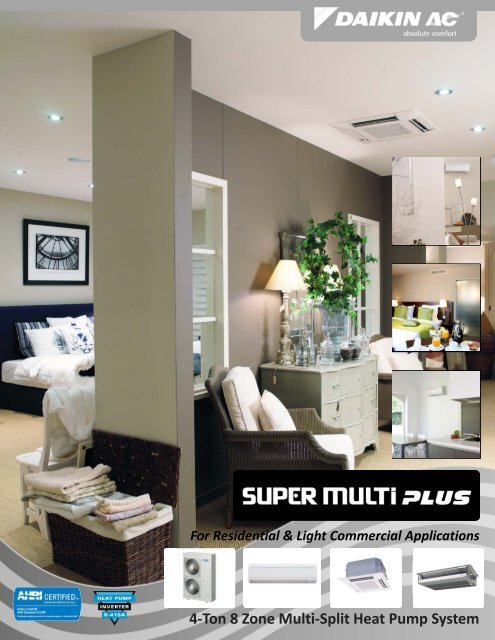
For Residential & Light Commercial Applications4‐<strong>Ton</strong> 8 <strong>Zone</strong> <strong>Multi</strong>‐<strong>Split</strong> <strong>Heat</strong> <strong>Pump</strong> <strong>System</strong>
EXPERTISE AND INNOVATIONThe Super <strong>Multi</strong> PLUS <strong>Split</strong> <strong>System</strong> is the ultimate, flexible solutionfor individual zone comfort. Connecting up to 8 indoor units to asingle outdoor unit reduces installation space andcosts while maximizing comfort and energy savings.With a choice of three indoor unit types in a widerange of capacities, the Super <strong>Multi</strong> Plus allowsmixed and matched combinations forabsolute comfort in almost any residential application.ENERGY EFFICIENCYIntegrated with an inverter “variable speed”compressor, <strong>Daikin</strong> Super <strong>Multi</strong> PLUS systems deliver thecapacity required to maintain desired room conditions,typically reducing energy consumption by 30% compared totraditional fixed speed systems. This technology minimizestemperature fluctuations and provides continuous coolingand heating comfort with maximum energy savings.INDIVIDUAL COMFORT AND CONTROLThe standard wireless controller provides individual temperature controlat the click of the button. Most Indoor units are also compatible with thenew <strong>Daikin</strong> ENVi intelligent thermostat, offering a more advancedsolution, designed with energy savings performance in mind. With thefreedom to access, program and control the system from a smart phone,tablet, or computer, users can have peace of mind ‐ anytime, anywhere.BUILT‐IN RELIABILITYNote: The <strong>Daikin</strong> ENVi thermostatis not compatible with the FFQIndoor UnitsAll major components are engineered andmanufactured by <strong>Daikin</strong>, ensuring maximumperformance, reliability and efficiency. Thestandard warranty provides a solid level ofprotection on the Super <strong>Multi</strong> PLUS system.<strong>System</strong>s installed by an authorized <strong>Daikin</strong>Dealer who has completed <strong>Daikin</strong>’s advancedtraining can take advantage of Warranty Plus–the best warranty in the industry.Find a <strong>Daikin</strong> Dealer near you atwww.daikinac.com.
DESIGN FLEXIBILITYThe Super <strong>Multi</strong> PLUS <strong>Split</strong> <strong>System</strong> can be combined with a variety of ducted and ductless modelswith a total of 15 indoor unit variations.Indoor Unit AvailabilityCapacityIndoor Type 7 MBH 9 MBH 12 MBH 15 MBH 18 MBH 24 MBHWall MountSlim Duct2' x 2' CassetteCTXS_H, CTXS_LV, FTXS_LVWall Mounted UnitBlends with any décor with it’s sleek and sophisticated designEnhanced indoor air quality with the titanium apatite photocatalytic airpurification filter which absorbs microscopic particles and decomposesodorsIncreased energy savings with the intelligent eye function which reducesoperation in unoccupied spacesFDXS_LV, CDXS_LVConcealed Slim DuctMaximized floor and wall space with it’s compact and concealed designUndisturbed comfort with low operating sound levelsCleaner air with the removal or airborne dust particles by the standardmold proof air filterNEW!FFQ_LV2’ X 2’ Ceiling CassetteEnhanced comfort with uniform airflow and temperature distributionDraught free protection with horizontal air dischargeSimple installation with an easy‐to‐fit decoration panel that blends withany interior designEasy maintenance with an easy‐to‐clean grille and washable long life filterBPMKSBranch Provider UnitVaries the refrigerant volume to meet the cooling or heating requirementsof each room connected to the system.Facilitates zone on/off and capacity control to operate rooms individuallyvia zone temperature controlsSimple installation with flare nut connectionsREFNET jointReduces the amount of work involved in installation and increases thereliability of the system.
LEADING TECHNICAL PERFORMANCEUp to 8 indoor units can beconnected to a single outdoor unitA High Efficiency solution with optimum flexibility to providezoning for with the connection of up to 8 indoor units utilizinglong pipe lengths, ease of installation with standardized linesets,simplified electrical requirements and stagedinstallationsOutdoor Units – RMXS48LVJUBP UnitsUp to 2 <strong>Zone</strong>s Up to 3 <strong>Zone</strong>sModel NameRMXS48LVJUModel Name BPMKS048A2U BPMKS049A3UNominal Capacity (Cooling / <strong>Heat</strong>ing) Btu/h 48,000 / 54,000Non Ducted 18.8 / 11.3SEER / HSPFMixed 16.5/10.5Ducted 14.1/9.6Non Ducted 10.3/3.0EER / COPMixed 9.8/2.9Power Supply Single phase 60Hz 208/230VDucted 9.3/2.7Power Consumption W 10 10Power Supply208/230V - 1Ø - 60Hz Running Current A 0.05 0.05Minimum Circuit Amps A 27.0Sound Pressure - (Cooling/<strong>Heat</strong>ing) dB(A) 32/32 32/32Maximum Overcurrent Protection A 30.0Number of Connectable Indoor Units 1 to 2 1 to 3Sound Pressure - (Cooling/<strong>Heat</strong>ing) dB(A) 56/58Min. Connection Combination 7,000 7,000Connection Ratio (Max Capacity for BPMKS Boxes) 50 - 130%Max. Connection Combination 48,000 62,000Number of Connectable Indoor Units 2 to 8Outdoor Unit Side in. Ø 1/4 x 2 Ø 1/4 x 3Number of Connectable BP Units 1 to 3Liquid Indoor Unit Side in. Ø 1/4 x 2 Ø 1/4 x 3Total <strong>System</strong> Piping Length ft. (m) 440 (135)PipingConnection Type Flare FlareMax. Piping Length(OU to BP Box) ft. (m) 180 (55)ConnectionsOutdoor Unit Side in. Ø 5/8 x 2 Ø 5/8 x 3Max. Piping Length(IU to BP Box) ft. (m) 49 (15)(O.D.)Gas Indoor Unit Side in. Ø 5/8 x 2 Ø 5/8 x 3Total Piping Length (OU to BP Box) ft. (m) 180 (55)Connection Type Flare FlareTotal Piping Length (BP to IU) ft. (m) 262 (80)Dimensions (H x W x D) in. 7-1/16 x 11-9/16 x 13-3/4Max. Piping Height (OU to IU) ft. (m) 98 (30)Net Weight lbs. 18.0 20.0Max. Piping Height (IU to BP Box) ft. (m) 98 (30)Max. Piping Height (BP to BP Box) ft. (m) 49 (15)Nominal Conditions:Cooling Mode<strong>Heat</strong>ing ModePiping Connection KitKHRP26A22TIndoor: 80 °F DB / 67 °F WB Indoor: 70 °F DBOperating Range – (Cooling/<strong>Heat</strong>ing) °F DB 23 – 115/5 - 75Note:Outdoor: 95 °F DBOutdoor: 47 °F DB / 43 °F WBSpecifications are subject to change without notice.Dimensions (H x W x D) in. 52-15/16 x 35-7/16 x 12-5/8 Pipe Length: 25 ft.Pipe Length: 25 ft.Net Weight lbs. 283.0Level Difference: 0 ft.Level Difference: 0 ft.Indoor Units - CTXS_HVJU, CTXS_LVJU, and FTXS_LVJU Wall Mounted Units0.6‐<strong>Ton</strong> 0.75‐<strong>Ton</strong> 1.0‐<strong>Ton</strong> 1.25‐<strong>Ton</strong> 1.5‐<strong>Ton</strong> 2.0‐<strong>Ton</strong>Model Name CTXS07LVJU CTXS09HVJU CTXS12HVJU FTXS15LVJU FTXS18LVJU FTXS24LVJUAirflow-Wet (H/M/L/SL) CFM 332/261/194/145 388/335/283/- 388/335/283/- 568/477/385/360 583/484/385/360 643/494/350/328Airflow-Dry (H/M/L/SL) CFM 350/290/233/219 400/357/314/- 400/357/314/- 593/505/417/371 625/526/431/399 699/572/445/403Sound Pressure - Cooling (H/M/L/SL) dB(A) 38/32/25/22 44/40/35/- 45/41/36/- 45/40/35/32 46/41/36/33 51/44/37/34Sound Pressure - <strong>Heat</strong>ing (H/M/L/SL) dB(A) 38/33/28/25 44/39/34/- 45/40/35/- 43/38/33/30 45/40/35/32 48/42/37/34Liquid (O.D.) in. Ø 1/4 Ø 1/4 Ø 1/4 Ø 1/4 Ø 1/4 Ø 1/4Piping ConnectionsGas (O.D.) in. Ø 3/8 Ø 3/8 Ø 3/8 Ø 1/2 Ø 1/2 Ø 5/8Condensate Drain Connection (O.D.) in. Ø 5/8 Ø 11/16 Ø 11/16 Ø 5/8 Ø 5/8 Ø 5/8Dimensions (H x W x D) in. 11-5/8 x 31-1/2 x 8-7/16 11-7/16 x 31-5/16 x 9-3/8 13-3/8 x 41-5/8 x 9-3/4Net Weight lbs. 20.0 20.0 20.0 31.0 31.0 31.0Indoor Units - FDXS_LVJU and CDXS_LVJU Slim Duct UnitsModel Name FDXS09LVJU FDXS12LVJU CDXS15LVJU CDXS18LVJU CDXS24LVJUExternal Static Pressure "W.G. 0.12 0.12 0.16 0.16 0.16Airflow-Wet (H/M/L/SL) CFM 305/280/260/235 305/280/260/235 424/388/353/297 424/388/353/297 424/388/353/297Airflow-Dry (H/M/L/SL) CFM 305/280/260/235 305/280/260/235 424/388/353/297 424/388/353/297 424/388/353/297Sound Pressure - Cooling (H/M/L/SL) dB(A) 35/33/31/- 35/33/31/- 37/35/33/31 37/35/33/31 37/35/33/31Sound Pressure - <strong>Heat</strong>ing (H/M/L/SL) dB(A) 35/33/31/- 35/33/31/- 37/35/33/31 37/35/33/31 37/35/33/31Liquid (O.D.) in. Ø 1/4 Ø 1/4 Ø 1/4 Ø 1/4 Ø 1/4Piping ConnectionsGas (O.D.) in. Ø 3/8 Ø 3/8 Ø 1/2 Ø 1/2 Ø 1/2Condensate Drain in. Ø 25/32 Ø 25/32 Ø 25/32 Ø 25/32 Ø 25/32Dimensions (H x W x D) in. 7-7/8 x 27-9/16 x 24-7/16 7-7/8x35-7/16x24-7/16Net Weight lbs. 47.0 47.0 60.0 60.0 60.0Indoor Units - FFQ_LVJU 2’x2’Duct UnitsModel Name FFQ09LVJU FFQ12LVJU FFQ15LVJU FFQ18LVJUAirflow Rate (H/L) CFM 318/230 353/230 424/283 530/353Sound Pressure - Cooling (H/L) dB(A) 35/33/31/- 35/33/31/- 37/35/33/31 37/35/33/31Sound Pressure - <strong>Heat</strong>ing (H/L dB(A) 35/33/31/- 35/33/31/- 37/35/33/31 37/35/33/31Liquid (O.D.) in. Ø 1/4 Ø 1/4 Ø 1/4 Ø 1/4Piping ConnectionsGas (O.D.) in. Ø 3/8 Ø 3/8 Ø 1/2 Ø 1/2Condensate Drain (O.D.) in. Ø 1-1/32 Ø 1-1/32 Ø 1-1/32 Ø 1-1/32Dimensions – Unit (H x W x D) in. 11-1/4 x 22-5/8 x 22-5/8Dimensions – Deco Panel (H x W x D) in. 2-1/4 x 27-5/8 x 27-5/8Net Weight lbs. 38.5 38.5 38.5 38.5
TIME‐SAVING INSTALLATION AND EASELonger Refrigerant PipingLonger refrigerant piping capabilitiesoffers much more flexibility in thechoice of installation positions for theindoor units, and greatly simplifiessystem layout.Piping RequirementsMaximumallowablelengthAllowable Length DetailsBetween outdoor and BP units Total piping length Piping length between outdoor and BP units ≤ 180 ft (55 m) - [Example] a+b+c+d+e ≤ 180 ftBetween BP and indoor units Total piping length Piping length between BP and indoor units: 262 ft (80 m) - [Example] f+g+h+i+j+k+l ≤ 262ftBetween BP and indoor unit 1 room length Piping length between BP and indoor unit ≤ 49 ft (15 m) - [Example] f, g, h, i, j, k, l ≤ 49 ftBetween outdoor and indoorunitsDifference in height between outdoor and indoor units (H1) ≤ 98 ft (30 m)AllowableheightBetween outdoor and BP units Difference in height between outdoor and BP units (H2) ≤ 98 ft (30 m)Difference inheightBetween BP and BP units Difference in height between BP and BP units (H3) ≤ 49 ft (15 m)Between indoor and indoor units Difference in height between indoor and indoor units (H4) ≤ 49 ft (15 m)Minimum allowable lengthAllowable length after the REFNET branchPiping lengthPipe length between outdoor unit and first refrigerant branch kit (refnet joint) ≥ 16.4 ft [Example] a ≥16.4 ftPiping length from first refrigerant branch kit (REFNET joint) to indoor unit ≤ 131 ft (40 m)[Example] unit 6: b+c+k ≤ 131 ft [Example] unit 5: b+e+j ≤ 131 ft [Example] unit 3: d+h ≤ 131 ftAdditional refrigerant calculationSimplified Electrical WiringThe outdoor unit and BP units operate from separate208/230V single‐phase power supplies. Indoor units arepowered from the BP unit and wired as <strong>Daikin</strong>’s current4 wire single split systems reducing the wiring size andeasing installationSpace Saving DesignMore than 60% in physical space savingsMore than 80% in total (including clearances)space savingsInstallation Space12‐5/8”<strong>Daikin</strong> RMXS35‐7/16”38‐11/16”Traditional Outdoor Unit35‐1/8”
<strong>System</strong> Operation RangeCooling Operation<strong>Heat</strong>ing Operation23 °FDB – 115 °FDBAmbient Temperature57 °FWB –82 °FDBIndoor Room Temperature5 °FDB –60 °FWBAmbient Temperature50 °FDB –82 °FDBIndoor Room TemperatureNote: No low ambient option exists with this product line.WARNINGS:• Always use a licensed installer or contractor to install this product. Do not try toinstall the product yourself. Improper installation can result in water or refrigerantleakage, electrical shock, fire or explosion.• Use only those parts and accessories supplied or specified by <strong>Daikin</strong>. Ask alicensed contractor to install those parts and accessories. Use of unauthorizedparts and accessories or improper installation of parts and accessories can result inwater or refrigerant leakage, electrical shock, fire or explosion.• Read the User’s Manual carefully before using this product. The User’s Manualprovides important safety instructions and warnings. Be sure to follow theseinstructions and warnings.For any inquiries, contact your local <strong>Daikin</strong> sales office.Use of the AHRI Certified mark indicates a manufacturer'sparticipation in the certification program. For verification ofcertification for individual products, go to www.ahridirectory.org© 2013 <strong>Daikin</strong> Industries, Limited.<strong>Daikin</strong>, <strong>Daikin</strong> <strong>AC</strong> Absolute Comfort, and its design, VRV, REFNET, Quaternity, <strong>Daikin</strong> Altherma are trademarks of <strong>Daikin</strong> Industries, LTD.www.likin-daikin.comDistributor or Dealer Information:<strong>Daikin</strong> <strong>AC</strong> (Americas), Inc.1645 Wallace Drive, Suite 110Carrollton, TX 75006www.daikinac.com866.4DAIKIN972.245.1510PFSMPUSE13-01RFor all equipment installation & application limitations please refer to the specific Engineering Data Books.<strong>Daikin</strong>’s products are subject to continuous improvements. <strong>Daikin</strong> reserves the right to modify product design, specifications and information in this brochure without noticeand without incurring any obligations.