931 PSA-UTENTE ed INSTALLATOR...
931 PSA-UTENTE ed INSTALLATOR...
931 PSA-UTENTE ed INSTALLATOR...

You also want an ePaper? Increase the reach of your titles
YUMPU automatically turns print PDFs into web optimized ePapers that Google loves.
INSTALLATION CERTIFICATEThe undersign<strong>ed</strong> qualifi<strong>ed</strong> installer attests to have personally fitt<strong>ed</strong> the here describ<strong>ed</strong> vehiclesecurity system following the manufacturer instructions.By :Sold on : T ype of product :................................................<strong>931</strong> <strong>PSA</strong><strong>931</strong> <strong>PSA</strong>Vehicle :..........................................................................................................................INSTALLATION ANDUSE MANUALUKGEMINI Technologies S.p.A.Via Luigi Galvani 12 - 21020 Bodio Lomnago (VA) - ItaliaTel. +39 0332 943211 - Fax +39 0332 948080Web site: www.gemini-alarm.comReg. n.532-AUNI EN ISO 9001:2008Made in Italy AC 2793 Rev. 00 - 09/10
UKTABLE OF CONTENTS1.0 - PRELIMINARY ADVICE............................................................................................. PAGE 022.0 - WARRANTY CONDITIONS .......................................................................................PAGE 02USER MANUAL3.0 - OPERATING DESCRIPTION..................................................................................... PAGE 033.1 - Complete system arming......................................................................................... PAGE 033.2 - Arming inhibit time.................................................................................................... PAGE 033.3 - System arm<strong>ed</strong>.......................................................................................................... PAGE 033.4 - Alarm, inhibit time between alarms and alarm cycles.............................................. PAGE 033.5 - System disarming..................................................................................................... PAGE 033.6 - Alarm memory........................................................................................................... PAGE 03INSTALLER MANUAL4.0 - CONNECTORS TABLES............................................................................................ PAGE 044.1 - 20-way connector..................................................................................................... PAGE 044.2 - 8-way connector....................................................................................................... PAGE 045.0 - COMPLETE ELECTRIC DIAGRAM........................................................................... PAGE 056.0 - ULTRASONIC VOLUMETRIC PROTECTION............................................................PAGE 056.1 - Connections and positioning........ ............................................................................ PAGE 056.2 - Sensor adjustment........ ............................................................................................ PAGE 057.0 - WASTE ELECTRICAL AND ELECTRONIC EQUIPMENT (WEEE) DIRECTIVE....... PAGE 0B8.0 - TECHNICAL SPECIFICATIONS............................................................................... PAGE 0B1.0 - PRELIMINARY ADVICEDear Customer, the present manual illustratesthe <strong>931</strong> <strong>PSA</strong> CAN enabl<strong>ed</strong> alarm system, customdesign<strong>ed</strong> for Peugeot/Citroën vehicles.Throughout this manual specific operating modes or connections are highlight<strong>ed</strong> by the followingsigns:!For the user.This sign highlights useful information.For the installer.This sign indicates that the functionning of the system can vary according toconnections and programming of the system or it simply provides useful indications forthe installation.2.0 - WARRANTY CONDITIONSThis product is guarante<strong>ed</strong> to be free from manufacturing defects for a period of 24 months from theinstallation date shown on this warranty, in compliance with the directive 1999/44/CE.Please fill-in entirely the guarantee certificate includ<strong>ed</strong> in this booklet and do NOT REMOVE theguarantee label from the device.The warranty will become void if labels are missing or torn, if the installation certificate is not fullycompil<strong>ed</strong> or if the enclos<strong>ed</strong> sale document is missing.The guarantee is valid exclusively at Authoriz<strong>ed</strong> Gemini Technologies S.p.A. Centers.The manufacturer declines any responsibility for eventual malfunctions of the device or any damageto the vehicle electrical system due to improper installation, use or tampering.This alarm system is solely intend<strong>ed</strong> to be a theft-deterrent device.USER MANUAL3.0 - OPERATING DESCRIPTION3.1 - COMPLETE SYSTEM ARMINGPress the lock button on the original remote control of the vehicle; the system arming is confirm<strong>ed</strong> bythe LED turn<strong>ed</strong> on steady for 30”( pre-arming “neutral time” ).3.2 - ARMING INHIBIT TIMESystem inhibit arming time lasts approximately 30 seconds and is indicat<strong>ed</strong> by the status LED on; it ispossible to exit the vehicle without triggering any alarm.3.3 - SYSTEM ARMEDAfter the inhibit time the system is “arm<strong>ed</strong>” and ready to detect any theft attempt.When the system is fully arm<strong>ed</strong>, the LED flashes.3.4 - ALARM, INHIBIT TIME BETWEEN ALARMS AND ALARM CYCLESThe system theft attempts is indicat<strong>ed</strong> by the system with optic signals (turn indicators) and acousticsignals (vehicle horn).After the alarm has been trigger<strong>ed</strong>, but before another alarm starts, there are 5” of “neutral time”.The alarm signalling has 10 cycles of 30” each for input and system arming cycles.3.5 - SYSTEM DISARMINGPress the unlock button on the original remote control of the vehicle; the system disarming isconfirm<strong>ed</strong> by the status LED off (blinking).If an alarm has occurr<strong>ed</strong>, the LED starts flashing when ignition key is turn<strong>ed</strong> “ON” to signal the lastalarm type.See relative paragraph (3.6) for possible causes and signals.To disarm the system in case of emergency (remote control out of order), simply turn ignitionkey “ON” with system arm<strong>ed</strong>.This type of disarming can ONLY be done with the vehicle ORIGINALKEY.3.6 - ALARM MEMORYAs previously mention<strong>ed</strong>, the LED memory allows you to identify the last alarm cause.After disarming the system,turn the ignition key “ON” and look at the vehicle status LED; the blinksindicates the last alarm condition.The optic signals are repeat<strong>ed</strong> 3 times; to interrupt, turn ignition key “OFF”.The alarm trigger signals and relative causes are indicat<strong>ed</strong> in the table below.LED OFF (2 seconds)LED SIGNALSLED ON (1 second)ALARM CAUSESStarting attempt (+15/54)Doors openingBonnet openingVolumetric sensorNr. OF ALARMCYCLES10101010PAGE 02USER MANUAL- PAGE 03
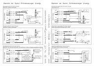
INSTALLER MANUAL5.0 - COMPLETE ELECTRIC DIAGRAM!For the system to work properly, the “original alarm install<strong>ed</strong>” feature (BSI unit)must first be enabl<strong>ed</strong> via the specific diagnostic tester available at any authoriz<strong>ed</strong>Peugeot-Citroën dealer (<strong>PSA</strong> group).Moreover, this type of system DOES NOT require that you program the vehiclecode, it is already factory-register<strong>ed</strong> by Gemini.NEVER PRESS THE PROGRAMMING BUTTON LOCATED NEXT TO THE UNITBUILT-IN LED!Before carrying out allelectrical connections,disconnect thenegative batteryterminal and reconnectagain aftercompletion.4.0 - CONNECTORS TABLES4.1 - 20-WAY CONNECTORPOSITION-1--2--3--4--5--6--7--8--9--10--11--12--13--14--15--16--17--18--19--20-WIRE FUNCTION------------------------------Grund for external sensor connectorLED negative outputLED positive output-----CAN BUS signal (CAN-H)CAN BUS signal (CAN-L)Positive output with system arm<strong>ed</strong> (+A)External sensor negative input------------------------------4.2 - 8-WAY CONNECTORWIRE COLOUR------------------------------BROWNBLACKRED-----LIGHT BLUE-GREYLIGHT BLUEPINKGREEN-BLACK-----------------------------R<strong>ed</strong>BlackGreen-BlackBrownPinkConnector for external modulesCAN BUS signalREDBLACKLIGHT BLUE (CAN-L)LIGHT BLUE-GREY (CAN-H) 4 16-way connector to plug intothe free connector mark<strong>ed</strong>“EA” on the BSI control unit6.0-ULTRASONIC VOLUMETRIC PROTECTION6.1 - CONNECTIONS AND POSITIONINGInsert the WHITE connector in the the “W” socket on the control unit.Insert the RED connector in the “R” socket on the control unit.Install the transducers of the ultrasonic sensors on the top part of the windscreen internal pillars, awayfrom the aeration inlets and orient them towards the center of the rear window.6.2 - SENSOR ADJUSTMENTo check sensors proce<strong>ed</strong> as follows: With system disarm<strong>ed</strong>, roll down the front window approx. 20 cm. Set the trimmer on the control unit to the middle position. Close doors, bonnet and boot and arm the system. During the system inhibit arming time, introduce an object in the cabin and move it around; thestatus LED will turn off to signal a presence. If sensibility level is too low, adjust trimmer again and repeat above proc<strong>ed</strong>ure.63POSITION-1--2--3--4--5--6--7--8-WIRE FUNCTIONGround-----Positive-------------------------WIRE COLOURBLACK-----RED-------------------------SENSIBILITYADJUSTMENTULTRASONICCELLSCONNECTIONSPAGE 04 - INSTALLER MANUALINSTALLER MANUAL - PAGE 05
7.0 - DIRETTIVA RIFIUTI DI APPARECCHIATURE ELETTRICHEED ELETTRONICHE (RAEE)Nell’Unione Europea, questa etichetta indica che, questo prodotto, non deve essere smaltitounitamente ai rifiuti domestici ma deve essere depositato presso un impianto adeguato <strong>ed</strong> in grado dieseguire le operazioni di recupero, smaltimento e riciclaggio (normative 2002/95/CE, 2002/96/CE e2003/108/CE).Per le informazioni sulle proc<strong>ed</strong>ure di riciclaggio responsabile di questo prodotto nel proprio Paesevisitare il sito: www.eur-lex.europa.eu!SOLOCONTENITORIAPPROPRIATI7.0 - WASTE ELECTRICAL AND ELECTRONIC EQUIPMENT(WEEE) DIRECTIVENelIn the European Union, this lable indicat<strong>ed</strong> that this product should not be dispos<strong>ed</strong> of withhousehold waste. It should be deposit<strong>ed</strong> at an appropriate facility to enable recovery and recycling(directive 2002/95/CE, 2002/96/CE and 2003/108/CE).For information on how to recycle this product responsibly in your Country, please visit the web-site:Www.eur-lex.europa.eu!APPROPRIATECONTAINER ONLY8.0 - CARATTERISTICHE TECNICHE8.0 - TECHNICAL SPECIFICATIONSTensione nominaleAssorbimento di corrente @ 12Vdc a sistema inserito e LED lampeggianteRange temperatura di funzionamentoDurata di un ciclo d’allarme12 Vdc15 mADa -30°C a +70°C30 sec.Power supplyCurrent absorption @ 12Vdc with system arm<strong>ed</strong> and LED flashingWorking range temperatureAlarm cycle duration12 Vdc15 mADa -30°C a +70°C30 sec.PAGE 0B