SK750/SK755 Operator's Manual - Ditch Witch
SK750/SK755 Operator's Manual - Ditch Witch
SK750/SK755 Operator's Manual - Ditch Witch

You also want an ePaper? Increase the reach of your titles
YUMPU automatically turns print PDFs into web optimized ePapers that Google loves.
<strong>SK750</strong>/<strong>SK755</strong> Operator’s <strong>Manual</strong> Overview - 2Chapter ContentsSerial Number Location . . . . . . . . . . . . . . . . . . . . . . 3Intended Use . . . . . . . . . . . . . . . . . . . . . . . . . . . . . . . 4Equipment Modification . . . . . . . . . . . . . . . . . . . . . . 4Unit Components . . . . . . . . . . . . . . . . . . . . . . . . . . . 5Operator Orientation. . . . . . . . . . . . . . . . . . . . . . . . . 6About This <strong>Manual</strong> . . . . . . . . . . . . . . . . . . . . . . . . . . 7• Bulleted Lists. . . . . . . . . . . . . . . . . . . . . . . . . . . . . . . . . . . . . . . . . . . . . . 7• Numbered Lists. . . . . . . . . . . . . . . . . . . . . . . . . . . . . . . . . . . . . . . . . . . . 7OverviewCMW
Overview - 3Serial Number Location<strong>SK750</strong>/<strong>SK755</strong> Operator’s <strong>Manual</strong>Serial Number LocationRecord serial numbers and date of purchase in spaces provided. Unit serial number is located as shown.t35om034w.epsItemdate of manufacturedate of purchaseunit serial numberengine serial numberCMW
<strong>SK750</strong>/<strong>SK755</strong> Operator’s <strong>Manual</strong> Overview - 4Intended UseIntended UseThe <strong>SK750</strong>/<strong>SK755</strong> is a platform, rubber track mini skid steer unit designed for light-to medium-dutyconstruction work. The <strong>SK750</strong>/<strong>SK755</strong> has a quick attach mount plate which makes it easy for an operatorto connect different attachments. The unit is designed for operation in temperatures typically experiencedin earth moving and construction work environments. Provisions may be required to operate in extremetemperatures. Contact your <strong>Ditch</strong> <strong>Witch</strong> dealer. Use in any other way is considered contrary to theintended use.The <strong>SK750</strong>/<strong>SK755</strong> should be operated, serviced, and repaired only by persons familiar with its particularcharacteristics and acquainted with the relevant safety procedures.Equipment ModificationThis equipment was designed and built in accordance with applicable standards and regulations.Modification of equipment could mean that it will no longer meet regulations and may not function properlyor in accordance with the operating instructions. Modification of equipment should only be made bycompetent personnel possessing knowledge of applicable standards, regulations, equipment designfunctionality/requirements and any required specialized testing.CMW
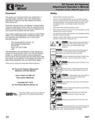
Overview - 5Unit Components<strong>SK750</strong>/<strong>SK755</strong> Operator’s <strong>Manual</strong>Unit Components1 2 3 4 5t35om001w.eps1. Operator station2. Tracks3. Engine compartment4. Lift arms5. Mount plateCMW
<strong>SK750</strong>/<strong>SK755</strong> Operator’s <strong>Manual</strong> Overview - 6Operator OrientationOperator Orientation1. Front of unit2. Right side of unit3. Rear of unit4. Left side of unit1423t35om002w.epsCMW
Overview - 7About This <strong>Manual</strong><strong>SK750</strong>/<strong>SK755</strong> Operator’s <strong>Manual</strong>About This <strong>Manual</strong>This manual contains information for the proper use of this machine. See the beige Operation Overviewpages for basic operating procedures. Cross references such as “See page 50” will direct you to detailedprocedures.Bulleted ListsBulleted lists provide helpful or important information or contain procedures that do not have to beperformed in a specific order.Numbered ListsNumbered lists contain illustration callouts or list steps that must be performed in order.CMW
<strong>SK750</strong>/<strong>SK755</strong> Operator’s <strong>Manual</strong> Foreword - 8ForewordThis manual is an important part of your equipment. It provides safety information and operationinstructions to help you use and maintain your <strong>Ditch</strong> <strong>Witch</strong> equipment.Read this manual before using your equipment. Keep it with the equipment at all times for future reference.If you sell your equipment, be sure to give this manual to the new owner.If you need a replacement copy, contact your <strong>Ditch</strong> <strong>Witch</strong> dealer. If you need assistance in locating adealer, visit our website at www.ditchwitch.com or write to the following address:The Charles Machine Works, Inc.Attn: Marketing DepartmentPO Box 66Perry, OK 73077-0066USAThe descriptions and specifications in this manual are subject to change without notice. The CharlesMachine Works, Inc. reserves the right to improve equipment. Some product improvements may havetaken place after this manual was published. For the latest information on <strong>Ditch</strong> <strong>Witch</strong> equipment, see your<strong>Ditch</strong> <strong>Witch</strong> dealer.Thank you for buying and using <strong>Ditch</strong> <strong>Witch</strong> equipment.CMW
Foreword - 9<strong>SK750</strong>/<strong>SK755</strong> Operator’s <strong>Manual</strong><strong>SK750</strong>/755Operator’s <strong>Manual</strong>Issue number 1.0/OM-9/12Part number 053-2570Copyright 2012by The Charles Machine Works, Inc.Machine Works, Inc., <strong>Ditch</strong> <strong>Witch</strong>, CMW, and Roto <strong>Witch</strong> are registered trademarks of The CharlesCMW
<strong>SK750</strong>/<strong>SK755</strong> Operator’s <strong>Manual</strong> Contents - 10ContentsOverviewmachine serial number, information about the type of work this machine is designedto perform, basic machine components, and how to use this manualForewordpart number, revision level, and publication date of this manual, and factory contactinformationSafetymachine safety alerts and emergency proceduresControlsmachine controls, gauges, and indicators and how to use them281222Prepareprocedures for inspecting and classifying the jobsite, planning the installation path (ifneeded), preparing the jobsite for work, and connecting attachmentsDriveprocedures for startup, cold start, driving, and shutdownTransportprocedures for lifting, hauling, and towing303842Complete the Jobprocedures for restoring the jobsite and rinsing and storing equipment50Serviceservice intervals and instructions for this machine including lubrication, replacementof wear items, and basic maintenanceSpecificationsmachine specifications including weights, measurements, power ratings, and fluidcapacitiesSupportthe warranty policy for this machine, and procedures for obtaining warrantyconsideration and trainingService Recorda record of major service performed on the machine52747882CMW
Contents - 11<strong>SK750</strong>/<strong>SK755</strong> Operator’s <strong>Manual</strong>CMW
<strong>SK750</strong>/<strong>SK755</strong> Operator’s <strong>Manual</strong> Safety - 12Chapter ContentsGuidelines . . . . . . . . . . . . . . . . . . . . . . . . . . . . . . . . 13Safety Alert Classifications . . . . . . . . . . . . . . . . . . 14Safety Alerts . . . . . . . . . . . . . . . . . . . . . . . . . . . . . . 15Emergency Procedures . . . . . . . . . . . . . . . . . . . . . 18• Electric Strike Description . . . . . . . . . . . . . . . . . . . . . . . . . . . . . . . . . . 18• If an Electric Line is Damaged . . . . . . . . . . . . . . . . . . . . . . . . . . . . . . . 19• If a Gas Line is Damaged . . . . . . . . . . . . . . . . . . . . . . . . . . . . . . . . . . . 19• If a Fiber Optic Cable is Damaged . . . . . . . . . . . . . . . . . . . . . . . . . . . . 20• If Machine Catches on Fire . . . . . . . . . . . . . . . . . . . . . . . . . . . . . . . . . 20SafetyCMW
Safety - 13Guidelines<strong>SK750</strong>/<strong>SK755</strong> Operator’s <strong>Manual</strong>GuidelinesFollow these guidelines before operating any jobsite equipment:• Complete proper training and read operator’s manual before using equipment.• Contact your local One-Call (811 in USA) or the One-Call referral number (888-258-0808 in USA andCanada) to have underground utilities located before digging. Also contact any utilities that do notparticipate in the One-Call service.• Classify jobsite based on its hazards and use correct tools and machinery, safety equipment, and workmethods for jobsite.• Mark jobsite clearly and keep spectators away.• Wear personal protective equipment.• Review jobsite hazards, safety and emergency procedures, and individual responsibilities with allpersonnel before work begins. Safety videos are available from your <strong>Ditch</strong> <strong>Witch</strong> dealer.• Replace missing or damaged safety shields and safety signs.• Use equipment carefully. Stop operation and investigate anything that does not look or feel right.• Do not operate unit where flammable gas is present.• Contact your <strong>Ditch</strong> <strong>Witch</strong> dealer if you have any question about operation, maintenance, or equipmentuse.CMW
<strong>SK750</strong>/<strong>SK755</strong> Operator’s <strong>Manual</strong> Safety - 14Safety Alert ClassificationsSafety Alert ClassificationsThese classifications and the icons defined on the following pages work together to alert you to situationswhich could be harmful to you, jobsite bystanders or your equipment. When you see these words andicons in the book or on the machine, carefully read and follow all instructions. YOUR SAFETY IS ATSTAKE.Watch for the three safety alert levels: DANGER, WARNING and CAUTION. Learn what each levelmeans.serious injury.indicates an imminently hazardous situation which, if not avoided, will result in death orserious injury.indicates a potentially hazardous situation which, if not avoided, could result in death orindicates a potentially hazardous situation which, if not avoided, may result in minor ormoderate injury.Watch for two other words: NOTICE and IMPORTANT.NOTICE can keep you from doing something that might damage the machine or someone's property. Itcan also alert you against unsafe practices.IMPORTANT can help you do a better job or make your job easier in some way.CMW
Safety - 15Safety Alerts<strong>SK750</strong>/<strong>SK755</strong> Operator’s <strong>Manual</strong>Safety AlertsMoving digging teeth will kill you or cut off arm or leg. Stay away.Turning shaft will kill you or crush arm or leg. Stay away.Electric shock. Contacting electric lines will cause death or serious injury.Know location of lines and stay away.Deadly gases. Lack of oxygen or presence of gas will cause sickness ordeath. Provide ventilation.Jobsite hazards could cause death or serious injury. Usecorrect equipment and work methods. Use and maintain proper safetyequipment.Crushing weight could cause death or serious injury. Useproper procedures and equipment or stay away.Moving parts could cut off hand or foot. Stay away.CMW
<strong>SK750</strong>/<strong>SK755</strong> Operator’s <strong>Manual</strong> Safety - 16Safety AlertsExplosion possible. Serious injury or equipment damage could occur.Follow directions carefully.Incorrect procedures could result in death, injury, or property damage.Learn to use equipment correctly.Improper control function could cause death or serious injury. If control doesnot work as described in instructions, stop machine and have it serviced.Looking into fiber optic cable could result in permanent vision damage. Donot look into ends of fiber optic or unidentified cable.Pressurized fluid or air could pierce skin and cause injury ordeath. Stay away.Runaway possible. Machine could run over you or others. Learn how to useall controls. Start and operate only from operator’s position.Fire or explosion possible. Fumes could ignite and cause burns. Nosmoking, no flame, no spark.Moving traffic - hazardous situation. Death or serious injury could result.Avoid moving vehicles, wear high visibility clothing, post appropriate warning signs.CMW
Safety - 17<strong>SK750</strong>/<strong>SK755</strong> Operator’s <strong>Manual</strong>Safety AlertsTipover possible. Machine can tip over and crush you.• Always operate with load end uphill.• Always carry load low. High load can cause tipping, loss of load or loss ofvisibility.• Never jerk control levers. Use a steady even motion.• See page 75 for tip capacity.Flying objects may cause injury. Wear hard hat and safety glasses.Hot parts may cause burns. Do not touch until cool.protection.Exposure to high noise levels may cause hearing loss. Wear hearingFall possible. Slips or trips may result in injury. Keep area clean.Battery acid may cause burns. Avoid contact.Improper handling or use of chemicals may result in illness, injury, orequipment damage. Follow instructions on labels and in material safety data sheets(MSDS).CMW
<strong>SK750</strong>/<strong>SK755</strong> Operator’s <strong>Manual</strong> Safety - 18Emergency ProceduresEmergency ProceduresBefore operating any equipment, review emergency procedures and check that all safety precautions havebeen taken.EMERGENCY SHUTDOWN - Turn ignition switch to STOP.Electric Strike DescriptionWhen working near electric cables, remember the following:• Electricity follows all paths to ground, not just path of least resistance.• Pipes, hoses, and cables will conduct electricity back to all equipment.• Low voltage current can injure or kill. Many work-related electrocutions result from contact with lessthan 440 volts.Most electric strikes are not noticeable, but indications of a strike include:• power outage• smoke• explosion• popping noises• arcing electricityIf any of these occur, assume an electric strike has occurred.CMW
Safety - 19If an Electric Line is Damaged<strong>SK750</strong>/<strong>SK755</strong> Operator’s <strong>Manual</strong>Emergency ProceduresIf you suspect an electric line has been damaged and you are on platform, DO NOT MOVE. Remain onplatform and take the following actions. The order and degree of action will depend upon the situation.• Warn people nearby that an electric strike has occurred. Instruct them to leave the area and contactutility.• Raise attachments and drive from immediate area.• Contact utility company to shut off power.• Do not return to jobsite or allow anyone into area until given permission by utility company.If you suspect an electric line has been damaged and you are off platform, DO NOT TOUCH UNIT. Takethe following actions. The order and degree of action will depend upon the situation.• LEAVE AREA. The ground surface may be electrified, so take small steps with feet close together toreduce the hazard of being shocked from one foot to the other. For more information, contact your<strong>Ditch</strong> <strong>Witch</strong> dealer.• Contact utility company to shut off power.• Do not return to jobsite or allow anyone into area until given permission by utility company.If a Gas Line is DamagedIf you suspect a gas line has been damaged, take the following actions. The order and degree of action willdepend on the situation.• Immediately shut off engine(s), if this can be done safely and quickly.• Remove any ignition source(s), if this can be done safely and quickly.• Warn others that a gas line has been cut and that they should leave the area.• Leave jobsite as quickly as possible.• Immediately call your local emergency phone number and utility company.• If jobsite is along street, stop traffic from driving near jobsite.• Do not return to jobsite until given permission by emergency personnel and utility company.CMW
<strong>SK750</strong>/<strong>SK755</strong> Operator’s <strong>Manual</strong> Safety - 20Emergency ProceduresIf a Fiber Optic Cable is DamagedDo not look into cut ends of fiber optic or unidentified cable. Vision damage can occur.If Machine Catches on FirePerform emergency shutdown procedure and then take the following actions. The order and degree ofaction will depend on the situation.• Immediately move battery disconnect switch (if equipped) to disconnect position.• If fire is small and fire extinguisher is available, attempt to extinguish fire.• If fire cannot be extinguished, leave area as quickly as possible and contact emergency personnel.CMW
Safety - 21<strong>SK750</strong>/<strong>SK755</strong> Operator’s <strong>Manual</strong>Emergency ProceduresCMW
<strong>SK750</strong>/<strong>SK755</strong> Operator’s <strong>Manual</strong> Controls - 22Gauges and IndicatorsControlsGauges and Indicators16342789510t35om003w.eps1. Glow plug button2. Engine coolant temperature gauge3. Engine oil pressure indicator4. Hydraulic fluid temperature indicator5. Hydraulic fluid level sight glass6. Ignition switch7. Hourmeter8. Engine coolant temperature indicator9. Glow plug indicator10. Fuel gaugeCMW
Controls - 23<strong>SK750</strong>/<strong>SK755</strong> Operator’s <strong>Manual</strong>Gauges and IndicatorsItem Description Notes1. Glow plug button To help start cold engine, turnignition switch to first position.IMPORTANT: Press glow plug buttonaccording to temperatures below.c00ic108h.eps2. Engine coolanttemperature gauge3. Engine oil pressureindicatorPress glow plug button asdirected in notes.Release button, then turnignition switch all the wayclockwise to start.Displays coolant temperature.Lights when engine oilpressure is low.Also lights briefly whenengine is started.• If ambient temperature is below40° F (4° C), press and holdbutton for 5 seconds.• If ambient temperature is below20° F (-7° C), press and holdbutton for 10 seconds.• Do not press button for more than20 seconds continuously.IMPORTANT: If temperature goesabove 230°F (110°C):1. Stop operation, set throttle to lowidle, and allow engine to cool.2. Stop engine.3. Check coolant level.4. Ensure radiator is clean.Engine will stop.1. Check oil level.2. Check for leaks before startingengine.4. Hydraulic fluidtemperature indicatorLights and alarm soundswhen hydraulic fluid isoverheating.Check hydraulic fluid level.Reduce load.Ensure oil cooler is clean.5. Hydraulic fluid sightglassShows level of hydraulic fluidin tank. Maintain fluid athalfway point on glass.CMW
<strong>SK750</strong>/<strong>SK755</strong> Operator’s <strong>Manual</strong> Controls - 24Gauges and IndicatorsItem Description Notes6. Ignition switch To start engine, insert key andturn clockwise.To stop engine, turn keycounterclockwise.IMPORTANT:• If engine does not start or stalls,turn key to STOP and thenrestart.• Do not allow starter motor to runcontinuously for more than 20seconds.7. Hourmeter Displays engine operatingtime.Use these times to schedule service.8. Engine coolanttemperature indicatorLights and alarm soundswhen engine coolanttemperature is too high.1. Stop operation, set throttle to lowidle, and allow engine to cool.2. Stop engine.3. Check coolant level.9. Glow plug indicator Lights when ignition switch ison and glow plug button ispressed.10. Fuel tank sight window Shows level of fuel in tank. NOTICE: Use low sulfur or ultra lowsulfur fuel only.CMW
Controls - 25Controls<strong>SK750</strong>/<strong>SK755</strong> Operator’s <strong>Manual</strong>Controls1526374t35om004w.eps1. Left track drive control orTrack drive joystick (optional)2. Right track drive control orTrack drive joystick (optional)3. Throttle4. Parking brake lever5. Lift arm control6. Attachment drive control7. Attachment drive foot controlCMW
<strong>SK750</strong>/<strong>SK755</strong> Operator’s <strong>Manual</strong> Controls - 26ControlsItem Description Notes1. Left track drive control2. Right track drivecontrolTo move forward, push.To move backward, pull.To go faster in eitherdirection, move control fartherfrom neutral position.To stop, move to neutralposition.To turn right, move left control fartherforward than right control.To turn left, move right control fartherforward than left control.To counter-rotate in either direction,move controls in opposite directionsas indicated above.Track drive joystick(optional)lTo move forward, push.To move backward, pull.To go faster in eitherdirection, move control fartherfrom neutral.To stop, move to neutral.To steer while moving forward, pushjoystick forward, then move left orright. Unit will gradually turn left orright.To steer while moving backward, pulljoystick back, then move left or right.Unit will gradually turn left or right.For tight steering in low speed, movejoystick to center position then to leftor right side. Tracks will counter rotateand turn unit in a tight circle.3. Throttle To increase engine speed,push.Increasing engine speed alsoincreases attachment speed.To decrease engine speed,pull.CMW
Controls - 27<strong>SK750</strong>/<strong>SK755</strong> Operator’s <strong>Manual</strong>ControlsItem Description Notes4. Parking brake lever To engage, rotate levercounterclockwise.To disengage, rotate leverclockwise.c00ic662w.eps5. Lift arm control To move lift arms down, push.To float, push forward to end.IMPORTANT: Exercise caution whenlifting loads. See page 75 foroperating capacities.6. Attachment drivecontrolTo move lift arms up, pull.To curl attachment up, moveto left.To curl attachment down,move to right.To engage attachment drivein reverse, lift lever lock andpush forward.To engage attachment drivein forward, lift lever lock andpull back.IMPORTANT:• Lever lock engages when controlis in neutral.• Use foot pedal to hold attachmentcontrol in the on position whenhands are busy operating lift armor track drive controls.7. Attachment drive footcontrolTo hold attachment drive inengaged position (forward orreverse), lift lever lock, movelever in desired direction, andpress pedal.To return attachment drivecontrol to neutral, releasepedal.IMPORTANT: Use foot pedal to holdattachment control in the on positionwhen hands are busy operating liftarm or track drive controls.CMW
<strong>SK750</strong>/<strong>SK755</strong> Operator’s <strong>Manual</strong> Controls - 28Engine CompartmentEngine Compartment1 2t35om016w.eps1. Hydraulic Fluid Bypass 2. Auxiliary outletItem Description Notes1. Hydraulic Fluid Bypass To open bypass valve, pulland rotate knob until it seatsin the open position.c00ic663w.epsStart engine and run fiveminutes to warm hydraulicfluid.To close bypass valve, rotateknob until it seats in theclosed position.IMPORTANT:• Use the hydraulic fluid bypass toassist starting a cold engine.• Tool carrier and attachment willnot operate correctly when knobis pulled out.2. Auxiliary power outlet To operate work lights orother 12V devices, plug intooutlet.CMW
Controls - 29Tool Carrier<strong>SK750</strong>/<strong>SK755</strong> Operator’s <strong>Manual</strong>Tool Carrier1. Level indicatorItem Description Notes1. Level indicator To level bucket, adjust bucketposition until indicator is attop of sleeve.To level other attachments, adjustattachment position until it is level.Mark indicator position on sleeve. Usemark to indicate level with thatattachment.CMW
<strong>SK750</strong>/<strong>SK755</strong> Operator’s <strong>Manual</strong> Prepare - 30Chapter ContentsGather Information . . . . . . . . . . . . . . . . . . . . . . . . . 31• All Jobs . . . . . . . . . . . . . . . . . . . . . . . . . . . . . . . . . . . . . . . . . . . . . . . . . 31• Ground-Penetrating Jobs . . . . . . . . . . . . . . . . . . . . . . . . . . . . . . . . . . . 31• Above-Ground Jobs . . . . . . . . . . . . . . . . . . . . . . . . . . . . . . . . . . . . . . . 31Inspect Site . . . . . . . . . . . . . . . . . . . . . . . . . . . . . . . 32• Identify Hazards . . . . . . . . . . . . . . . . . . . . . . . . . . . . . . . . . . . . . . . . . . 32Classify Jobsite . . . . . . . . . . . . . . . . . . . . . . . . . . . 33• Inspect Jobsite . . . . . . . . . . . . . . . . . . . . . . . . . . . . . . . . . . . . . . . . . . . 33• Select a Classification . . . . . . . . . . . . . . . . . . . . . . . . . . . . . . . . . . . . . 33• Apply Precautions . . . . . . . . . . . . . . . . . . . . . . . . . . . . . . . . . . . . . . . . 34Check Supplies and Prepare Equipment . . . . . . . 35• Supplies . . . . . . . . . . . . . . . . . . . . . . . . . . . . . . . . . . . . . . . . . . . . . . . . 35• Fluid Levels . . . . . . . . . . . . . . . . . . . . . . . . . . . . . . . . . . . . . . . . . . . . . 35• Condition and Function . . . . . . . . . . . . . . . . . . . . . . . . . . . . . . . . . . . . 35• Accessories . . . . . . . . . . . . . . . . . . . . . . . . . . . . . . . . . . . . . . . . . . . . . 35Connect Attachment . . . . . . . . . . . . . . . . . . . . . . . 36PrepareCMW
Prepare - 31Gather Information<strong>SK750</strong>/<strong>SK755</strong> Operator’s <strong>Manual</strong>Gather InformationA successful job begins before you start working. The first step in planning is reviewing information alreadyavailable about the job and jobsite.All JobsReview Job PlanReview blueprints or other plans. Check for information about existing or planned structures, elevations, orproposed work that may be taking place at the same time.Arrange for Traffic ControlIf working near a road or other traffic area, contact local authorities about safety procedures andregulations.Plan for Emergency ServicesHave the telephone numbers for local emergency and medical facilities on hand. Check that you will haveaccess to a telephone.Ground-Penetrating JobsNotify One-Call ServicesContact your local One-Call (811 in USA) or the One-Call referral number (888-258-0808 in USA andCanada) to have underground utilities located before digging. Also contact any utilities that do notparticipate in the One-Call service.Above-Ground JobsLocate Overhead LinesNote location and height of all overhead lines in jobsite and ensure that fully lifted attachment and/or loadwill not touch lines.CMW
<strong>SK750</strong>/<strong>SK755</strong> Operator’s <strong>Manual</strong> Prepare - 32Inspect SiteInspect SiteInspect jobsite before transporting equipment. Check for the following:• changes in elevation such as hills or other open trenches• obstacles such as buildings, railroad crossings, or streams• signs of utilities (See “Inspect Jobsite” on page 33.)• traffic• access• soil type and conditionIdentify HazardsIdentify safety hazards and classify jobsite if attachment will penetrate ground. See “Classify Jobsite” onpage 33.Jobsite hazards could cause death or serious injury. Usecorrect equipment and work methods. Use and maintain proper safetyequipment.To help avoid injury:• Wear personal protective equipment including hard hat, safety eye wear, and hearing protection.• Do not wear jewelry or loose clothing.• Notify One-Call and companies which do not subscribe to One-Call.• Comply with all utility notification regulations before digging or drilling.• Verify location of previously marked underground hazards.• Mark jobsite clearly and keep spectators away.Remember, jobsite is classified by hazards in place -- not by line being installed.CMW
Prepare - 33Classify Jobsite<strong>SK750</strong>/<strong>SK755</strong> Operator’s <strong>Manual</strong>Classify JobsiteInspect Jobsite• Inspect jobsite and perimeter for evidence of underground hazards, such as:– “buried utility” notices– utility facilities without overhead lines– gas or water meters– junction boxes– drop boxes– light poles– manhole covers– sunken ground• Follow U.S. Department of Labor regulations on excavating and trenching (Part 1926, Subpart P) andother similar regulations.• Contact your local One-Call (811 in USA) or the One-Call referral number (888-258-0808 in USA andCanada) to have underground utilities located before digging. Also contact any utilities that do notparticipate in the One-Call service.• Have an experienced locating equipment operator sweep area within 20’ (6 m) to each side of workpath. Verify previously marked line and cable locations.• Mark location of all buried utilities and obstructions.• Classify jobsite.Select a ClassificationJobsites are classified according to underground hazards present.If working . . . then classify jobsite as . . .within 10’ (3 m) of a buried electric linewithin 10’ (3 m) of a natural gas linein sand or granite which is capable of producing crystalline silica(quartz) dustwithin 10’ (3 m) of any other hazardelectricnatural gascrystalline silica (quartz) dustotherNOTICE: If you have any doubt about jobsite classification, or if jobsite might contain unmarkedhazards, take steps outlined previously to identify hazards and classify jobsite before working.CMW
<strong>SK750</strong>/<strong>SK755</strong> Operator’s <strong>Manual</strong> Prepare - 34Classify JobsiteApply PrecautionsOnce classified, precautions appropriate for jobsite must be taken.Electric Jobsite PrecautionsUse one or both of these methods.• Expose line by careful hand digging or soft excavation.• Have service shut down while work is in progress. Have electric company test lines before returningthem to service.Natural Gas Jobsite PrecautionsIn addition to positioning equipment upwind from gas lines, use one or both of these methods.• Expose lines by careful hand digging or soft excavation.• Have gas shut off while work is in progress. Have gas company test lines before returning them toservice.Crystalline Silica (Quartz) Dust PrecautionsCutting, drilling, or working materials such as concrete, sand, or rock containing quartz may result inexposure to silica dust. Use water spray or other means to control dust. If workers are exposed to dustthey must wear appropriate breathing protection. Silica dust may cause lung disease and is known to theState of California to cause cancer.Other Jobsite PrecautionsYou may need to use different methods to safely avoid other underground hazards. Talk with thoseknowledgeable about hazards present at each site to determine which precautions should be taken or ifjob should be attempted.CMW
Prepare - 35Check Supplies and Prepare EquipmentSupplies• fuel<strong>SK750</strong>/<strong>SK755</strong> Operator’s <strong>Manual</strong>Check Supplies and Prepare EquipmentNOTICE: Use low sulfur or ultra low sulfur fuel only.• keys• lubricants• personal protective equipment, such as hard hat and safety glassesFluid Levels• fuelNOTICE: Use low sulfur or ultra low sulfur fuel only.• hydraulic fluid• battery charge• engine oilCondition and Function• parking brake pins (See “Check Brake Operation” on page 59.)• filters (air, oil, hydraulic)• tracks• pumps and motors• hoses and valves• signs, guards, and shieldsAccessoriesFire ExtinguisherIf required, mount a fire extinguisher near the power unit but away from possible points of ignition. The fireextinguisher should always be classified for both oil and electric fires. It should meet legal and regulatoryrequirements.CMW
<strong>SK750</strong>/<strong>SK755</strong> Operator’s <strong>Manual</strong> Prepare - 36Connect AttachmentConnect AttachmentNOTICE: Use only <strong>Ditch</strong> <strong>Witch</strong>-approved attachments. Attachments can change the stability andoperating characteristics of the unit.AttachmentIMPORTANT: Before connecting attachment to unit,ensure that mount and receiver plates are free of dirtand debris.1. Position attachment on level surface with enoughspace behind it to accommodate unit.2. Ensure that lock pin handles (shown) on mountplate are turned away from center of attachment.3. Start engine.4. Tilt mount plate (2) forward.5. Position mount plate in the upper lip of the receiverplate (1) on attachment.6. Raise lift arms while tilting back mount plate.t05om022c.eps21IMPORTANT: Attachment should be raisedenough to clear the ground. Mount plateshould be tilted back fully.7. Turn ignition switch off and remove key.t05om026c.epsIncorrect procedures could result in death, injury, or property damage.Learn to use equipment correctly.To help avoid injury: Ensure proper connection by verifying that bottoms of lock pins arevisible under attachment receiver plate (shown).8. Rotate lock pin handles toward center of mount plateto secure attachment to lift plate.t05om027c.epsCMW
Prepare - 37Hydraulic Hoses<strong>SK750</strong>/<strong>SK755</strong> Operator’s <strong>Manual</strong>Connect AttachmentIf attachment requires hydraulic power for operation, connect hydraulic hoses.Pressurized fluid or air could pierce skin and cause injuryor death. Stay away.To help avoid injury:• Escaping pressurized fluid can cause injury or pierce skin and poison.• Before disconnecting a hydraulic line, turn engine off and operate all controls to relieve pressure.Lower, block, or support any raised component with a hoist. Cover connection with heavy cloth andloosen connector nut slightly to relieve residual pressure. Catch all fluid in a container.• Before using system, check that all connections are tight and all lines are undamaged.• Use a piece of cardboard or wood, rather than hands, to search for leaks.• Wear protective clothing, including gloves and eye protection.• If you are injured, seek immediate medical attention from a doctor familiar with this type of injury.Hot parts may cause burns. Do not touch until cool.To help avoid injury: Wear gloves when connecting and disconnecting hydraulic hosesand wait until unit has cooled before touching hydraulic components.1. Cycle attachment drive control to relieveresidual pressure at hydraulic couplers.2. Remove dirt and debris from hydrauliccouplers.3. Connect male coupler on attachment to femalecoupler (3) on unit.4. Connect female coupler on attachment to malecoupler (1) on unit.5. If needed, connect attachment case drain hoseto case drain connector (2).6. Ensure that connections are secure by pullingon hoses.t35om011w.eps123CMW
<strong>SK750</strong>/<strong>SK755</strong> Operator’s <strong>Manual</strong> Drive - 38Chapter ContentsStart Unit . . . . . . . . . . . . . . . . . . . . . . . . . . . . . . . . . 39Drive . . . . . . . . . . . . . . . . . . . . . . . . . . . . . . . . . . . . . 39Shut Down . . . . . . . . . . . . . . . . . . . . . . . . . . . . . . . . 41DriveCMW
Drive - 39Start Unit<strong>SK750</strong>/<strong>SK755</strong> Operator’s <strong>Manual</strong>Start Unit1. Ensure all controls are in neutral.2. If necessary, use glow plugs and/or hydraulic fluid bypass control to warm cold engine. See “HydraulicFluid Bypass” on page 28.3. Move throttle to half open.4. Turn ignition switch to start position and release when engine starts.NOTICE: If jump starting is required, see “Jump Start Unit” on page 70.EMERGENCY SHUTDOWN: Turn ignition switch to STOP.DriveGeneral OperationTo help avoid injury:1. Disengage parking brake.2. Pull lift arm control to raise mount plate (and attachment) off ground.3. Move track drive control to steer unit. See page 26.Tipover possible. Machine can tip over and crush you.• Always operate with load end uphill.• Always carry load low. High load can cause tipping, loss of load or loss ofvisibility.• Never jerk control levers. Use a steady even motion.• See page 75 for tip capacity.IMPORTANT: If needed for attachment operation, push attachment drive foot control to holdattachment control in the forward position while operating track drive and lift arm controls.4. Adjust throttle as needed.5. See attachment operation manual for instructions regarding proper operation of attachments.CMW
<strong>SK750</strong>/<strong>SK755</strong> Operator’s <strong>Manual</strong> Drive - 40DriveSafe Slope OperationTo help avoid injury:Operating safely on a slope depends upon many factors including:Tipover possible. Machine can tip over and crush you.• Always operate with heavy end uphill.• Always carry load low. High load can cause tipping, loss of load or loss ofvisibility.• Drive cautiously at all times.• Never jerk control levers. Use a steady even motion.• Do not park unit on slope without lowering attachment to the ground,returning all controls to neutral position, shutting down unit, and applyingparking brake.• See “Tipping capacity” on page 75.• Distribution of machine weight, including front loading and absence of load• Height of load• Even or rough ground conditions• Potential for ground giving way causing unplanned tilt forward, reverse or sideways• Nearness of ditches, ruts, stumps or other obstructions and sudden changes in slope• Speed• Turning• Braking performance• Operator skillThese varying factors make it impractical to specify a maximum safe operating angle in this manual. It istherefore important for the operator to be aware of these conditions and adjust operation accordingly.Maximum engine angle and braking performance are two absolute limits which must never be exceeded.These maximums are stated below since they are design limits. These design limits usually exceed theoperating limits and must never be used alone to establish safe operating angle for variableconditions.Maximum engine lubrication angle – 20°Maximum service brake retarding force – equal to traction of both tracks.Maximum park brake holding force – equal to traction of one track.CMW
Drive - 41Shut Down<strong>SK750</strong>/<strong>SK755</strong> Operator’s <strong>Manual</strong>Shut Down1. Lower lift arms to ground.2. Move all controls to neutral position.3. Apply parking brake.4. Run engine at low idle for five minutes to cool.NOTICE: Failure to allow engine to cool before shutdown may damage turbocharger.5. Turn ignition switch to STOP.6. Remove key.CMW
<strong>SK750</strong>/<strong>SK755</strong> Operator’s <strong>Manual</strong> Transport - 42Chapter ContentsLift . . . . . . . . . . . . . . . . . . . . . . . . . . . . . . . . . . . . . . 43• Points . . . . . . . . . . . . . . . . . . . . . . . . . . . . . . . . . . . . . . . . . . . . . . . . . . 43• Procedure . . . . . . . . . . . . . . . . . . . . . . . . . . . . . . . . . . . . . . . . . . . . . . . 43Haul . . . . . . . . . . . . . . . . . . . . . . . . . . . . . . . . . . . . . 44• Load . . . . . . . . . . . . . . . . . . . . . . . . . . . . . . . . . . . . . . . . . . . . . . . . . . . 44• Tie Down . . . . . . . . . . . . . . . . . . . . . . . . . . . . . . . . . . . . . . . . . . . . . . . 45• Unload . . . . . . . . . . . . . . . . . . . . . . . . . . . . . . . . . . . . . . . . . . . . . . . . . 46Tow . . . . . . . . . . . . . . . . . . . . . . . . . . . . . . . . . . . . . 47TransportCMW
Transport - 43Lift<strong>SK750</strong>/<strong>SK755</strong> Operator’s <strong>Manual</strong>LiftCrushing weight. If load falls or moves it could kill or crush you. Useproper procedures and equipment or stay away.To help avoid injury: Only lift unit without attachment installed.PointsLifting points are identified by lifting decals. Lifting at other points is unsafeand can damage machinery.ProcedureUse a hoist capable of supporting theequipment's size and weight. See“Specifications” on page 74 or measure andweigh equipment before lifting.Use one of the methods below:• Use two points nearest operator station.IMPORTANT: Front of unit will be lower thanrear of unit when using only two lift points.• Use three lift points as shown.t35om022w.epsCMW
<strong>SK750</strong>/<strong>SK755</strong> Operator’s <strong>Manual</strong> Transport - 44HaulHaulLoadCrushing weight. If load falls or moves it could kill or crush you. Useproper procedures and equipment or stay away.To help avoid injury:• Load and unload trailer on level ground.• Incorrect loading can cause trailer swaying.• Attach trailer to vehicle before loading or unloading.• Only operate unit from operator platform.• To help prevent trailer sway, load trailer so that ten to fifteen percent of total vehicle weight(equipment plus trailer) is on tongue.• If loading onto tilt-bed trailer, be prepared for trailer to tilt.• Move all controls to neutral position when stopped.1. Disengage parking brake.2. Start engine.3. Adjust throttle to low speed.4. Pull lift arm control to raise mount plate (and attachment) clear of trailer, but keep it low.5. Move unit to rear of trailer and align with ramps.6. Drive forward slowly to move unit onto trailer until tiedown position is reached.7. Push lift arm control to lower mount plate (and attachment) to trailer bed.8. Engage parking brake.9. Ensure that all controls are in neutral position.10. Turn ignition switch to STOP.11. Tie down unit.CMW
Transport - 45Tie Down<strong>SK750</strong>/<strong>SK755</strong> Operator’s <strong>Manual</strong>HaulPointsTiedown points are identified by tiedown decals. Securing to truck or trailerat other points is unsafe and can damage machinery.ProcedureLoop tiedowns around unit at tiedown points. Make sure tiedowns are tight before transporting.t35om005w.epsCMW
<strong>SK750</strong>/<strong>SK755</strong> Operator’s <strong>Manual</strong> Transport - 46HaulUnloadCrushing weight. If load falls or moves it could kill or crush you. Useproper procedures and equipment or stay away.To help avoid injury:• Load and unload trailer on level ground.• Attach trailer to vehicle before loading or unloading.• Only operate unit from operator platform.• If unloading from tilt-bed trailer, be prepared for trailer to tilt.1. Prepare trailer and ramps for unloading.2. Remove tiedowns.3. Disengage parking brake.4. Start engine.5. Pull lift arm control to raise mount plate (and attachment) off ground, but keep it low.6. Adjust throttle to low speed and slowly back unit down trailer or ramps.CMW
Transport - 47Tow<strong>SK750</strong>/<strong>SK755</strong> Operator’s <strong>Manual</strong>TowIncorrect procedures could result in death, injury, or property damage.Learn to use equipment correctly.Under normal conditions, unit should not be towed. If unit breaks down and towing is necessary:t35om007w.epsrear tow pointt35om006w.epsfront tow point• attach chains to tow points facing towing vehicle• tow for short distances at less than 1 mph (1.6 km/h)• do not tow for more than 100’ (30 m)• use no more than 1,300 lb (5800 N) of towing force• open bypass valve on each pump sectionNOTICE: When bypass valve is open, unit has no brakes.• disengage parking brakeCMW
<strong>SK750</strong>/<strong>SK755</strong> Operator’s <strong>Manual</strong> Transport - 48TowPrepare Unit for Towing1. Block tracks.2. Engage parking brake (shown).3. Loosen bypass valves (shown) three turns.t35om008w.epsIMPORTANT: Open bypass valves in bothfront and rear pumps.NOTICE: When bypass valves are open, unithas no brakes.t35om012w.epsReturn Unit to Normal Operation1. Tighten bypass valves and tighten locknut to 15-18 ft•lb (20-25 N•m).IMPORTANT: Close bypass valve in both front and rear pumps.2. Disengage parking brake.3. Unblock tracks.CMW
Transport - 49<strong>SK750</strong>/<strong>SK755</strong> Operator’s <strong>Manual</strong>TowCMW
<strong>SK750</strong>/<strong>SK755</strong> Operator’s <strong>Manual</strong> Complete the Job - 50Chapter ContentsRinse Equipment . . . . . . . . . . . . . . . . . . . . . . . . . . 51Disconnect Attachment . . . . . . . . . . . . . . . . . . . . . 51Stow Tools . . . . . . . . . . . . . . . . . . . . . . . . . . . . . . . 51Complete the JobCMW
Complete the Job - 51Rinse Equipment<strong>SK750</strong>/<strong>SK755</strong> Operator’s <strong>Manual</strong>Rinse Equipment1. Spray water onto equipment to remove dirt and mud.NOTICE: Do not spray water onto operator’s console. Electrical components could be damaged.Wipe down instead.2. Open hood and allow unit to cool. Remove debris from inside of unit.3. Remove mud from track sprockets.4. Wash undercarriage. Pay special attention to brake pin area.Disconnect Attachment1. Lower attachment to the ground.2. Turn off engine.3. Disengage lock pins by turning handles away from center of attachment.4. Cycle attachment drive control and disconnect hydraulic hoses, if used.5. Start engine.6. Tilt mount plate forward and back unit away from attachment.Stow ToolsMake sure all tools and accessories are loaded and properly secured on trailer.CMW
<strong>SK750</strong>/<strong>SK755</strong> Operator’s <strong>Manual</strong> Service - 52Chapter ContentsPrecautions . . . . . . . . . . . . . . . . . . . . . . . . . . . . . . 53Overview . . . . . . . . . . . . . . . . . . . . . . . . . . . . . . . . . 55Recommended Lubricants/Service Key . . . . . . . 55Engine Oil Temperature Chart . . . . . . . . . . . . . . . 5610 Hour . . . . . . . . . . . . . . . . . . . . . . . . . . . . . . . . . . 5850 Hour . . . . . . . . . . . . . . . . . . . . . . . . . . . . . . . . . . 62200 Hour. . . . . . . . . . . . . . . . . . . . . . . . . . . . . . . . . . 65500 Hour . . . . . . . . . . . . . . . . . . . . . . . . . . . . . . . . . 672000 Hour . . . . . . . . . . . . . . . . . . . . . . . . . . . . . . . . 69As Needed . . . . . . . . . . . . . . . . . . . . . . . . . . . . . . . 69ServiceCMW
Service - 53Precautions<strong>SK750</strong>/<strong>SK755</strong> Operator’s <strong>Manual</strong>PrecautionsIncorrect procedures could result in death, injury, or property damage.Learn to use equipment correctly.To help avoid injury:• Unless otherwise instructed, perform all service with engine off.• Refer to engine manufacturer’s manual for engine maintenance instructions.• Before servicing equipment, lower unstowed attachments to ground.Working Under Raised Lift ArmsCrushing weight could cause death or serious injury. Useproper procedures and equipment or stay away.To help avoid injury: Support both lift arms before working under raised lift arms.Use safety supports as indicated when working underraised lift arms.CMW
<strong>SK750</strong>/<strong>SK755</strong> Operator’s <strong>Manual</strong> Service - 54PrecautionsJump Starting PrecautionExplosion possible. Serious injury or equipment damage could occur.Follow directions carefully.To help avoid injury:• Keep sparks and flames away from battery. Battery gas can explode.• Follow instructions to prevent damage to electronic components.• Only jump-start in extreme circumstances. Follow procedures on page 70 if jump starting isnecessary.Welding PrecautionExplosion possible. Serious injury or equipment damage could occur.Follow directions carefully.NOTICE:• Disconnect battery to prevent damage to battery. Do not turn off battery disconnect switchwith engine running, or alternator and other electronic devices may be damaged.• Connect welder ground clamp close to welding point and make sure no electroniccomponents are in the ground path.• Always disconnect the Engine Control Unit ground connection from the frame, harnessconnections to the ECU, and other electronic components prior to welding on machine orattachments.CMW
Service - 55Overview<strong>SK750</strong>/<strong>SK755</strong> Operator’s <strong>Manual</strong>Overviewt35om035w.epsRecommended Lubricants/Service KeyItemDescriptionDEOTHFDiesel engine oil meeting API service classification CF-4 or E1-96 and SAE viscosityrecommended by engine manufacturer (SAE 15W40)Tractor hydraulic fluid, similar to Phillips 66 HG, Mobilfluid 423, Chevron TractorHydraulic Fluid, Texaco TDH Oil, or equivalentMPG Multipurpose grease meeting NLGI GC-LB Grade 2* Initial service intervalCheck level of fluid or lubricantCheck conditionFilterChange, replace, adjust, service or testProper lubrication and maintenance protects <strong>Ditch</strong> <strong>Witch</strong> equipment from damage and failure. Serviceintervals listed are for minimum requirements. In extreme conditions, service machine more frequently.CMW
<strong>SK750</strong>/<strong>SK755</strong> Operator’s <strong>Manual</strong> Service - 56Engine Oil Temperature ChartUse only recommended lubricants. Fill to capacities listed on page 75.NOTICE:• Use only genuine <strong>Ditch</strong> <strong>Witch</strong> parts, filters, and approved lubricants to maintain warranty.• Use the “Service Record” on page 82 to record all required service to your machine.Engine Oil Temperature ChartTemperature range anticipated before next oil changeFor more information on engine lubrication and maintenance, see your engine manual.Approved CoolantsThis unit was filled with John Deere Cool-Gard coolant before shipment from factory. Add only Cool-Gard(p/n 255-006) or any fully-formulated, ethylene glycol based, low-silicate, heavy-duty diesel engine coolantmeeting ASTM specification D5345 (prediluted) or D4985 (concentrate). Before using any other kind ofcoolant, completely flush radiator.NOTICE: Do not mix heavy-duty diesel engine coolant and automotive-type coolant. This will leadcoolant breakdown and engine damage.CMW
Service - 57Approved Fuel<strong>SK750</strong>/<strong>SK755</strong> Operator’s <strong>Manual</strong>Engine Oil Temperature ChartThe engine is this unit is designed to run on diesel fuel. Use only high-quality fuel meeting ASTM D975 No.2D, EN590, or equivalent. At temperatures below 32°F (0°C), winter fuel blends are acceptable. Seeengine operation manual for more information.IMPORTANT:• For machines operated in the U.S.: The engine in this product is certified to operate on low sulfurdiesel fuel (LSD) with a sulfur content of 500 ppm (0.05%) or less. Use LSD or ultra low sulfur fuel(ULSD) only. Using fuels with higher sulfur content will affect exhaust emissions. Such action is aviolation of the US Clean Air Act and US EPA regulations and will result in fines.• For machines operated outside the U.S.: Fuel sulfur content should be less than 5000 ppm (0.05%).Worldwide fuel sulfur regulations vary widely. Fuel used should always comply with localregulations. If fuel sulfur content exceeds 5000 ppm, use a lube oil meeting API CF (or equivalent)with a TBN value of 10 or greater. Do not use lube oils meeting API CJ-4 (or other low SAPSequivalent) under any conditions.Biodiesel blends up to 5% (B5) are approved for use in this unit. The fuel must meet the specifications fordiesel fuel shown above. In certain markets, higher blends may be used if certain steps are taken. Extraattention is needed when using biodiesel, especially when operating in cold weather or storing fuel.Contact your <strong>Ditch</strong> <strong>Witch</strong> dealer or the engine manufacturer for more information.CMW
<strong>SK750</strong>/<strong>SK755</strong> Operator’s <strong>Manual</strong> Service - 58Startup/10 HourStartup/10 HourTaskCheck engine oil levelNotesDEOCheck engine air filter service indicatorCheck engine coolant levelGrease front track idler rollersCheck hydraulic fluid levelDEACMPGTHFCheck brake operationCheck track tensionCheck hydraulic hosesCheck Engine Oil LevelCheck engine oil level at dipstick opening (1) atstartup and every 10 hours. Oil level should be attop of marking. If low, add DEO at fill (2). Checkwith unit on level surface and at least 15 minutesafter stopping engine.12IMPORTANT: Use oil specified in“Engine Oil Temperature Chart” onpage 56.Check Engine Air Filter ServiceIndicatort35om009w.epsCheck air filter service indicator (shown) at startupand every 10 hours and change filter as needed.See “Change Air Filter” on page 69.t35om010w.epsCMW
Service - 59<strong>SK750</strong>/<strong>SK755</strong> Operator’s <strong>Manual</strong>Startup/10 HourCheck Hydraulic Fluid LevelCheck hydraulic fluid level at startup and every10 hours. Maintain fluid level at halfway point onsight glass (2), when engine is off, cylinders arefully retracted, and fluid is cool. If low, add THF atfill (1).21t35om013w.epsCheck Brake OperationCheck brake operation at startup and every 10hours or more often when conditions warrant.• Ensure parking brake pin(shown) movesfreely allowing brake to be engaged anddisengaged.• Clean mud and debris from area around pin.t35om014w.epsCMW
<strong>SK750</strong>/<strong>SK755</strong> Operator’s <strong>Manual</strong> Service - 60Startup/10 HourCheck Track TensionCheck track tension at startup and every 10hours and adjust as needed. Track is correctlytensioned when measurement between track andstraight edges (2) is 1/2 in (13 mm).To adjust:1. Park machine on smooth flat surface.2. Lay straight edge on top of track, spanningfrom sprocket to front idler roller.3. Clean track cylinder zerk (1). Pump MPG intozerk until distance between track and straightedge (2) is 1/2” (13 mm).4. Test: Drive forward one track length andcheck tension again.• If tension is too loose, repeat step 3above.• If tension is too tight, loosen fitting ongrease cylinder and allow a smallamount of grease to discharge fromcylinder. Tighten fitting and test again.1t35om033w.eps2Check Coolant LevelCheck coolant level, with engine cool, at overflowbottle at startup and every 10 hours. Maintaincoolant level at halfway point on bottle. If low, addapproved coolant.IMPORTANT: See page 56 for information onapproved coolants.t35om015w.epsCMW
Service - 61<strong>SK750</strong>/<strong>SK755</strong> Operator’s <strong>Manual</strong>Startup/10 HourCheck Hydraulic HosesPressurized fluid or air could pierce skin and cause injuryor death. Stay away.To help avoid injury:• Before disconnecting a hydraulic line, turn engine off and operate all controls to relieve pressure.Lower, block, or support any raised component with a hoist. Cover connection with heavy cloth andloosen connector nut slightly to relieve residual pressure. Catch all fluid in a container.• Before using system, check that all connections are tight and all lines are undamaged.• Use a piece of cardboard or wood, rather than hands, to search for leaks.• Wear protective clothing, including gloves and eye protection.• If you are injured, seek immediate medical attention from a doctor familiar with this type of injury.Check hydraulic hoses for leaks at startup andevery 10 hours.CMW
<strong>SK750</strong>/<strong>SK755</strong> Operator’s <strong>Manual</strong> Service - 6250 Hour50 HourTaskChange engine oil and filterCheck fan belt tension and damageChange hydraulic fluid filterNotesinitial service1/4-1/3” (7-9 mm)initialCheck fuel hose and clamp bandCheck radiator/hydraulic fluid cooler for dirt and debrisCheck battery electrolyte levelChange Engine Oil and Filter (Initial)Change engine oil after 50 hours. Drain oil (1)and add 4.2 qt (4 L) of DEO at fill (2).IMPORTANT: Use oil specified in “Engine OilTemperature Chart” on page 56.1t35om017w.eps2t35om018w.epsCMW
Service - 63<strong>SK750</strong>/<strong>SK755</strong> Operator’s <strong>Manual</strong>50 HourChange Hydraulic Filter (initial)Change hydraulic filter after 50 hours.t35om019w.epsCheck Fan Belt for Tension andDamageCheck belt tension every 50 hours. Belt isproperly tensioned when it moves about 1/4-3/8”(7-9 mm) when pushed at the long span. Replacethe belt when it is worn and sinks into the pulleygroove.Adjust Tension1. Loosen two alternator bolts (shown).2. Adjust position as needed.3. Tighten bolts.4. Check tension.Check Fuel Hose and Clamp BandsCheck fuel hose and clamp bands every 50hours.If the clamp is loose, apply oil to the threads andretighten it. If the hose is worn, replace it.Bleed the fuel system if the hose and/or clamp ischanged.CMW
<strong>SK750</strong>/<strong>SK755</strong> Operator’s <strong>Manual</strong> Service - 6450 HourCheck Radiator/Fluid CoolerCheck radiator/hydraulic fluid cooler for dirt,grass, and other foreign matter every 50 hours.Clean out with compressed air or spray wash ifrequired. Be careful not to damage fins with highpressureair or water. Check more often ifoperating in dusty or grassy conditions.Check radiator hoses for wear. Check hoseclamps for proper tightness.t35om020w.epsCheck BatteryExplosion possible. Serious injury or equipment damage could occur.Follow directions carefully.To help avoid injury:• Keep sparks and flames away from battery. Battery gas can explode.• Always remove negative (-) battery cable first and replace it last.• Do not splash battery electrolyte onto skin; it will burn and cause blindness if splashed into eyes.Wash hands after working around battery.• Never disconnect battery terminals with engine running. Voltage spike may occur and damageelectronic control modules or other components.Check battery every 100 hours. Keep battery andterminals clean and free of corrosion.Add distilled water if liquid level is low.CMW
Service - 65200 Hour<strong>SK750</strong>/<strong>SK755</strong> Operator’s <strong>Manual</strong>200 HourTaskChange engine oil and filterCheck intake air lineNotes4.2 qt (4 L) DEO1/4-1/3” (7-9 mm)Change hydraulic filterChange Engine Oil and FilterChange engine oil and filter every 200 hours.Drain oil, change filter (shown) and add 4.2 qt (4L) of DEO at fill. See page 62.IMPORTANT: Use oil specified in “Engine OilTemperature Chart” on page 56.Check Intake Air LineCheck the intake air line every 200 hours.NOTICE: Keep dust out of the intake air line toprevent damage to the engine.If the clamp is loose, apply oil to the threads andretighten it.If the hose appears cracked or worn, replace it.CMW
<strong>SK750</strong>/<strong>SK755</strong> Operator’s <strong>Manual</strong> Service - 66200 HourChange Hydraulic FilterChange hydraulic filter every 200 hours.t35om019w.epsCMW
Service - 67500 Hour<strong>SK750</strong>/<strong>SK755</strong> Operator’s <strong>Manual</strong>500 HourTaskNotesChange fuel filtersChange hydraulic fluid and filterChange Fuel FiltersChange filters every 500 hours. If you refuel fromcans, replace filters more often.The canister filter is located in the enginecompartment. The inline filter is located under thecontrol console.See parts manual or contact your <strong>Ditch</strong> <strong>Witch</strong>dealer for correct replacement filter.t35om028w.epst35om030w.epsCMW
<strong>SK750</strong>/<strong>SK755</strong> Operator’s <strong>Manual</strong> Service - 68500 HourChange Hydraulic Fluid and FilterChange hydraulic fluid and filter every 500 hours.Change every 250 hours if jobsite temperatureexceeds 100°F (38°C) more than 50% of thetime.1. Remove drain plug (3).2. Drain fluid and replace plug.3. Change filter. See page 66.4. Add THF at fill (1) until fluid level is at halfwaypoint on sight glass (2). Capacity is 9.2 gal(35 L).123t35om029w.epsCMW
Service - 692000 Hour<strong>SK750</strong>/<strong>SK755</strong> Operator’s <strong>Manual</strong>2000 HourChange Engine CoolantDrain cooling system at drain (2). Add approvedcoolant at fill (1) every two years or 2000 hours.1NOTICE:• The use of non-approved coolant maylead to engine damage or prematureengine failure and will void enginewarranty.• See page 56 for list of approved coolants.2t35om031w.epsAs NeededChange Air Filter13Change air filter when red band on indicator (1) isvisible. Replace safety element (4) every thirdchange of primary filter (3) or any time primaryelement has become damaged.1. Open air filter housing at latches (2).2. Remove primary element (3).3. Wipe inside of housing and end cup (2).4. Insert new primary element.5. Latch air filter case.6. Reset air filter service indicator (1).t35om032w.eps42CMW
<strong>SK750</strong>/<strong>SK755</strong> Operator’s <strong>Manual</strong> Service - 70As NeededJump Start UnitIncorrect procedures could result in death, injury, or property damage.Use equipment correctly.To help avoid injury:• Park on level area.• Put all drive controls in neutral and lower all unstowed attachments.• Turn off all electrical loads.• Turn off engine and remove key from ignition.• Block wheels or tracks.Explosion possible. Serious injury or equipment damage could occur.Follow directions carefully.To help avoid injury:• Lead-acid batteries vent explosive hydrogen gas when charging.• Do not smoke, create sparks, or use flames around batteries.• NEVER lean over battery when making connections.• Do not allow vehicles to touch when jump starting.• Wear eye protection and remove metal jewelry and watches.• Do not attempt to jump start a battery that is leaking, bulging, heavily corroded, frozen, or otherwisedamaged.• NEVER short-circuit battery terminals for any reason.• NEVER hammer on battery posts or cable terminals.CMW
Service - 71<strong>SK750</strong>/<strong>SK755</strong> Operator’s <strong>Manual</strong>As NeededBefore You StartElectronic components can be easily damaged by electrical surges. Jump starting can damage electronicsand electrical systems, and is not recommended except in extreme circumstances. Use quality largediameter jumper cables capable of carrying high currents (400 amps or more). Cheap cables may not allowenough current flow to start a dead/discharged battery.Read all steps thoroughly and review illustration before performing procedure.Jump Start Procedure (Engine Off)1. Park service vehicle close to disabled equipment but do not allow vehicles to touch.2. Engage parking brake in both vehicles.3. Turn the ignition switch to the OFF position in both vehicles, and turn off all electrical loads.4. Inspect battery in disabled vehicle (B) for signs of cracking, bulging, leaking, or other damage.Connect red positive (+) jumper cable clamp to positive (+) post (2) of battery in disabled vehicle first.IMPORTANT: Some equipment may have a positive jumper cable terminal (1) located externally.If so equipped, connect red positive (+) jumper cable clamp to terminal.5. Connect the other red positive (+) jumper cable clamp to positive (+) post of battery (A) in the servicevehicle.CMW
<strong>SK750</strong>/<strong>SK755</strong> Operator’s <strong>Manual</strong> Service - 72As Needed6. Connect black negative (-) cable clamp to negative (-) post of battery (A) in service vehicle.7. Connect the other black negative (-) cable clamp to the engine or frame ground on the disabledvehicle, at least 12” (305 mm) from the failed battery, as shown.8. Operate service vehicle engine at 1500-2000 rpm for a few minutes to build an electrical charge in thefailed battery.9. Stop engine in service vehicle.10. Remove jumper cables from the service vehicle, black negative (-) clamp first. Do not allow clamps totouch.11. Attempt to start disabled vehicle.12. If engine starts, operate at full throttle for a few minutes to build an electrical charge in the battery.13. Remove black negative (-) cable clamp from the disabled engine or frame ground first.14. Remove red positive (+) cable clamp from the disabled vehicle positive (+) battery post last.If the disabled vehicle did not start, check for loose or corroded battery cable connections. Poorconnections will prevent current from charging the failed battery. Clean terminals and posts if necessaryand repeat steps above. If a running jump is necessary, repeat steps above with engine running.NOTICE: Jumping with engine running can damage the alternator and electronic components on bothvehicles, and should be performed only if necessary.CMW
Service - 73<strong>SK750</strong>/<strong>SK755</strong> Operator’s <strong>Manual</strong>As NeededCMW
<strong>SK750</strong>/<strong>SK755</strong> Operator’s <strong>Manual</strong> Specifications - 74<strong>SK750</strong>/<strong>SK755</strong> Basic UnitSpecifications<strong>SK750</strong>/<strong>SK755</strong> Basic UnitLH2HA2L2WDimensions U.S. MetricH2 Hinge pin height, max 81 in 2057 mmOperating height, max, standard bucket 103 in 2615 mmH Overall height of machine 57 in 1450 mmL Overall length of loader, no attachment 86 in 2190 mmOverall length of machine, with standard bucket 105 in 1670 mmL2 Wheelbase/track length 43 in 1092 mmA2 Angle of departure 27° 27°Ground clearance, min (center/side) 8.9 in / 3.7 in 170 mm /124 mmW Track width, max 42 in 1065 mmTrack width, min 36 in 914 mmUnit width, excluding tracks 35 in 890 mmDump height, max, with standard bucket 64 in 1626 mmReach, standard bucket at max dump height 17 in 430 mmCMW
Specifications - 75<strong>SK750</strong>/<strong>SK755</strong> Operator’s <strong>Manual</strong><strong>SK750</strong>/<strong>SK755</strong> Basic UnitDimensions U.S. MetricBucket rollback angle, ground level 25° 25°Bucket rollback angle, full height 90° 90°Dump angle, standard bucket at max dump height 35° 35°Bucket width, max 44 in 1120 mmBucket width, min 36 in 915 mmSwing radius, max, with standard bucket 65 in 1650 mmSwing radius, no attachment 44 in 1120 mmRear overhang, max 29 in 735 mmPerformance U.S. MetricGround drive speed, forward and reverse 4.7 mph 7.6 km/hGround pressure, 7” (180 mm) tracks * 4.8 psi 0.33 barGround pressure, 9” (230 mm) tracks * 3.8 psi 0.26 barTipping capacity2285 lb 1039 kgThe rated operating capacity for this machine was determined using a standard bucket inthe drive position with center of gravity 7 in (18 cm) from the mounting plate. Dependingon the attachment, the actual operating capacity of the attachment may vary.Operating capacity (35% of tipping capacity) 800 lb 364 kgMachine weight (no attachment, fluids full) 2890 lb 1314 kg* Includes machine weight, 175-lb (80-kg) bucket, 165-lb (75-kg) operatorBatterySAE reserve capacity 110 min, SAE cold crank @ 0°F (-18°C) 800 amp, 12V electrical systemFluid Capacities U.S. MetricFuel tank 10.5 gal 40 LEngine oil, with filter 4.2 qt 4 LHydraulic reservoir 9.2 gal 35 LSpecifications are called out according to SAE recommended practices. Specifications are general and subject to change withoutnotice. If exact measurements are required, equipment should be weighed and measured. Due to selected options, deliveredequipment may not necessarily match that shown.CMW
<strong>SK750</strong>/<strong>SK755</strong> Operator’s <strong>Manual</strong> Specifications - 76<strong>SK750</strong> Power Specifications<strong>SK750</strong> Power SpecificationsPower U.S. MetricEngine: Kubota D1105, diesel, EPA Tier 4, EU Stage IIIaNumber of cylinders 3Displacement 68.5 in 3 1.12 LBore 3.07 in 78 mmStroke 3.09 in 78.4 mmManufacturer’s gross power rating (per SAE J1955) 23.1 hp 17.2 kWEstimated net power rating (per SAE 1348) 31.5 hp 23.5 kWRated engine speed 3000 rpm 3000 rpmHydraulic System U.S. MetricAuxiliary: double gear pumpFlow rate (pump 1) 6.5 gpm 24 L/minFlow rate (pump 2) 5.5 gpm 21 L/minPressure 3000 psi 207 barGround drive: dual hydrostatFlow rate 13.9 gpm 52 L/minPressure 3500 psi 241 barNoise LevelsOperator 87 dBA sound pressure per ISO 6394 Exterior 100 dBA sound power per ISO 6393Vibration LevelAverage vibration transmitted to the operator’s hand during normal operation with a loader bucket is4.31 m/sec 2. Average vibration transmitted to the whole body during normal operation with a loaderbucket is 1.07 m/sec 2 . Actual vibration will depend upon the attachment being used.Specifications are called out according to SAE recommended practices. Specifications are general and subject to change withoutnotice. If exact measurements are required, equipment should be weighed and measured. Due to selected options, deliveredequipment may not necessarily match that shown.CMW
Specifications - 77<strong>SK755</strong> Power Specifications<strong>SK750</strong>/<strong>SK755</strong> Operator’s <strong>Manual</strong><strong>SK755</strong> Power SpecificationsPower U.S. MetricEngine: Kubota D1105-T, diesel, EPA Tier 4, EU Stage IIIaNumber of cylinders 3Displacement 68.5 in 3 1.12 LBore 3.07 in 78 mmStroke 3.09 in 78.4 mmManufacturer’s gross power rating (per SAE J1955) 32.8 hp 24.5 kWEstimated net power rating (per SAE 1348) 31.5 hp 23.5 kWRated engine speed 3000 rpm 3000 rpmMaximum tilt angle, fore and aft 30° 30°Maximum tilt angle, side to side 30° 30°* Exceeding these operating angles will cause engine damage. This DOES NOT imply that the machine is stable to maximumangle of safe engine operation.Hydraulic System U.S. MetricAuxiliary: double gear pumpFlow rate (pump 1) 8.0 gpm 30 L/minFlow rate (pump 2) 5.5 gpm 21 L/minPressure 3000 psi 207 barGround drive: dual hydrostatFlow rate 13.9 gpm 52 L/minPressure 3500 psi 241 barNoise LevelsOperator 87 dBA sound pressure per ISO 6394 Exterior 101 dBA sound power per ISO 6393Vibration LevelVibration at the operator’s hand during normal operation is 4.31 m/sec 2Vibration at the operator’s foot during normal operation is 1.07 m/sec 2Specifications are called out according to SAE recommended practices. Specifications are general and subject to change withoutnotice. If exact measurements are required, equipment should be weighed and measured. Due to selected options, deliveredequipment may not necessarily match that shown.CMW
<strong>SK750</strong>/<strong>SK755</strong> Operator’s <strong>Manual</strong> Support - 78ProcedureSupportProcedureNotify your dealer immediately of any malfunction or failure of <strong>Ditch</strong> <strong>Witch</strong> equipment.Always give model, serial number, and approximate date of your equipment purchase. This informationshould be recorded and placed on file by the owner at the time of purchase.Return damaged parts to dealer for inspection and warranty consideration if in warranty time frame.Order genuine <strong>Ditch</strong> <strong>Witch</strong> replacement or repair parts from your authorized <strong>Ditch</strong> <strong>Witch</strong> dealer. Use ofanother manufacturer's parts may void warranty consideration.ResourcesPublicationsContact your <strong>Ditch</strong> <strong>Witch</strong> dealer for publications and videos covering safety, operation, service, and repairof your equipment.<strong>Ditch</strong> <strong>Witch</strong> TrainingFor information about on-site, individualized training, contact your <strong>Ditch</strong> <strong>Witch</strong> dealer.CMW
Warranty - 79<strong>SK750</strong>/<strong>SK755</strong> Operator’s <strong>Manual</strong>Warranty<strong>Ditch</strong> <strong>Witch</strong> Equipment and Replacement PartsLimited Warranty PolicySubject to the limitation and exclusions herein, free replacement parts will be provided at any authorized <strong>Ditch</strong> <strong>Witch</strong> dealership forany <strong>Ditch</strong> <strong>Witch</strong> equipment or parts manufactured by The Charles Machine Works, Inc. (CMW) that fail due to a defect in material orworkmanship within one (1) year of first commercial use (Exception: 2 years for all SK5 attachments). Free labor will be provided atany authorized <strong>Ditch</strong> <strong>Witch</strong> dealership for installation of parts under this warranty during the first year following “initial commercial”use of the serial-numbered <strong>Ditch</strong> <strong>Witch</strong> equipment on which it is installed. The customer is responsible for transporting theirequipment to an authorized <strong>Ditch</strong> <strong>Witch</strong> dealership for all warranty work.Exclusions from Product Warranty• All incidental or consequential damages.• All defects, damages, or injuries caused by misuse, abuse, improper installation, alteration, neglect, or uses other than those forwhich products were intended.• All defects, damages, or injuries caused by improper training, operation, or servicing of products in a manner inconsistent withmanufacturer’s recommendations.• All engines and engine accessories (these are covered by original manufacturer’s warranty).• Tires, belts, and other parts which may be subject to another manufacturer’s warranty (such warranty will be available topurchaser).• ALL IMPLIED WARRANTIES NOT EXPRESSLY STATED HEREIN, INCLUDING ANY WARRANTY OF FITNESS FOR APARTICULAR PURPOSE AND MERCHANTABILITY.IF THE PRODUCTS ARE PURCHASED FOR COMMERCIAL PURPOSES, AS DEFINED BY THE UNIFORM COMMERCIALCODE, THEN THERE ARE NO WARRANTIES WHICH EXTEND BEYOND THE FACE HEREOF AND THERE ARE NO IMPLIEDWARRANTIES OF ANY KIND WHICH EXTEND TO A COMMERCIAL BUYER. ALL OTHER PROVISIONS OF THIS LIMITEDWARRANTY APPLY INCLUDING THE DUTIES IMPOSED.<strong>Ditch</strong> <strong>Witch</strong> products have been tested to deliver acceptable performance in most conditions. This does not imply they will deliveracceptable performance in all conditions. Therefore, to assure suitability, products should be operated under anticipated workingconditions prior to purchase.Defects will be determined by an inspection within thirty (30) days of the date of failure of the product or part by CMW or its authorizeddealer. CMW will provide the location of its inspection facilities or its nearest authorized dealer upon inquiry. CMW reserves the rightto supply remanufactured replacements parts under this warranty as it deems appropriate.Extended warranties are available upon request from your local <strong>Ditch</strong> <strong>Witch</strong> dealer or CMW.Some states do not allow exclusion or limitation of incidental or consequential damages, so above limitation of exclusion may notapply. Further, some states do not allow exclusion of or limitation of how long an implied warranty lasts, so the above limitation maynot apply. This limited warranty gives product owner specific legal rights and the product owner may also have other rights which varyfrom state to state.For information regarding this limited warranty, contact CMW’s Product Support department, P.O. Box 66, Perry, OK 73077-0066, orcontact your local <strong>Ditch</strong> <strong>Witch</strong> dealer.First version: 1/91; Latest version: 7/05CMW
<strong>SK750</strong>/<strong>SK755</strong> Operator’s <strong>Manual</strong> Service Record - 82Service RecordService Performed Date HoursCMW
Service Record - 83<strong>SK750</strong>/<strong>SK755</strong> Operator’s <strong>Manual</strong>Service Performed Date HoursCMW