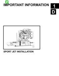
SECTION 6A â SPORT JET INSTALLATION
SECTION 6A â SPORT JET INSTALLATION
SECTION 6A â SPORT JET INSTALLATION

Create successful ePaper yourself
Turn your PDF publications into a flip-book with our unique Google optimized e-Paper software.
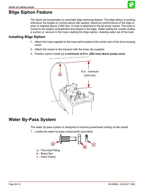
<strong>SPORT</strong> <strong>JET</strong> <strong>INSTALLATION</strong>Bilge Siphon FeatureInstalling Bilge SiphonThe Sport Jet incorporates an automatic bilge siphoning feature. The bilge siphon is workingwhenever the engine is running above idle speeds. Maximum performance of the bilge siphonis realized above 3,000 rpm. A hose is attached to the jet pump nozzle. The hose isrouted to the engine compartment and placed in the bilge. Water exiting the nozzle createsa suction or vacuum in the hose creating the bilge siphon, drawing water out of the boat.1. Attach the hose supplied to the hose barb located at the center rear of the drive housingcover.2. Attach the hoses to the transom with the hose clip supplied.3. Position siphon break (a) a minimum of 8 in. (203 mm) above pump cover.a8 in. minimum(203 mm)Water By-Pass SystemThe water by-pass system is designed to improve powerhead cooling at idle speed.1. Locate the water by-pass components (provided).aa -Thru-Hull Fittingb-Brass Nutc -Hose ClampbcPage <strong>6A</strong>-18 90-858804 AUGUST 1998