Muon Monitors - CNGS - CERN
Muon Monitors - CNGS - CERN
Muon Monitors - CNGS - CERN

You also want an ePaper? Increase the reach of your titles
YUMPU automatically turns print PDFs into web optimized ePapers that Google loves.
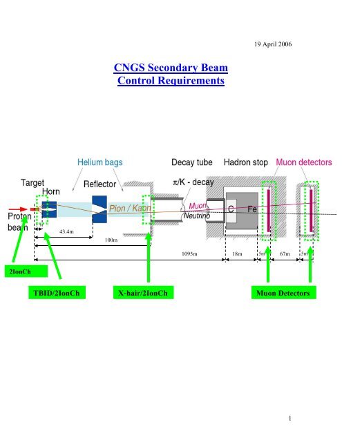
19 April 2006<strong>CNGS</strong> Secondary BeamControl Requirements2743.4m100m1095m 18m 5m 67m 5m2IonChTBID/2IonChX-hair/2IonCh<strong>Muon</strong> Detectors1
• Graphs of IC_COLL_L and IC_COLL_R versus extraction, cycle numbers andtime.Ionization Chambers at the TBID• Read IC_TBID_L = XGBL400002/BFCT• Read IC_TBID_R = XGBL400003/BFCT• Graphs of IC_TBID_L and IC_TBID_R versus extraction, cycle numbers andtime.Ionization Chambers at the Cross-Hair• Read IC_XHAIR_L = XGBL400094/BFCT• Read IC_XHAIR_R = XGBL400095/BFCT• Graphs of IC_XHAIR_L and IC_XHAIR_R versus extraction, cycle numbers andtime.Position/Angle scans for the IC_TBID_L and IC_TBID_R at the TBIDUsed magnets:i. MDSV412153ii. MDSH412244iii. MDSV412419iv. MDSH412422• Graph of IC_TBID_L, IC_TBID_R vs. scan parameter (position orangle)• Show value of BFCT (in the same graph)• Calculate centre value of measured distribution Examples of graph see muon monitors!!!Position/Angle scans for the IC_XHAIR_L and IC_XHAIR_R at the Cross-hairUsed magnets:v. MDSV412153vi. MDSH412244vii. MDSV412419viii. MDSH412422• Graph of IC_XHAIR_L, IC_XHAIR_R vs. scan parameter (position orangle)• Show value of BFCT (in the same graph)• Calculate centre value of measured distribution Examples of graph see muon monitors!!!3
Logging:• Log gain• The value of each ionization chamber has to be logged (BLML412445,BLMR412445, XGBL400002, XGBL400003, XGBL400094, XGBL400095).Note: this is in Gray. How do we log the conversion-factor from Gray to Charges?• Is it possible to log the double scans (ionization chambers vs. magnet currents). Itanyway will be calculated in CESAR. (Vito & Marine to discuss-> yes(15.11.05))Alarm:Ionization chambers at the collimator are hardware interlocked. → Alarm.Other alarms?• Alarm when IC_TBID_L/IC_TBID_R passes a certain threshold. → included inCESAR, sends Alarm to LASER• There will be software interlocks → then Alarm!4
A first draft of the functional specifications for the SEM acquisition systemthat is used for the TBID and the <strong>Muon</strong> <strong>Monitors</strong> can be found athttps://edms.cern.ch/file/639610/1/bestldDoc.pdfTBID (XGTB400003)TBID : Target Beam Instrumentation DownstreamBeamBiasRBSPHLU DBSPVBSIBSIBSHLRUDLRBSPHHorizontal beam positionBSIBeam intensityUDBSPHVVertical beam positionBSHHalo foil .Dead-line: January 2006.The output format of the TBID is in ‘charges’ (Unit = Coulomb) and are acquired usingthe FESA class ‘BESTLD’. (It will be up to <strong>CNGS</strong> experimenters to provide thecalibration factor Ccal n for each detector. By default all factors will be set to 1.0.)The reading of the current transformer BFCT412425 is the equivalent of ‘NORM2’ in theother EA beam-lines.All graphs/plots must be printable.5
GUI:Operator Level:• Set gain per channel (1,2,4,8,16) – corresponds to amplifier gain• Set gain for all foils (1, 10, 100) – corresponds to different capacitance• Display signal status (‘saturation-flag’: LOW, OK, HIGH)The elements that need to be read out are several foils in the TBID:• BSI 1• BSI 2• BSPHL• BSPHR• BSPVU• BSPVD• BSHand• BFCT (BFCT412425) using the FESA class BCTFIThe BFCT equipment will also return calibrated intensity data (charges).2. Intensity (from BSI integral foils)• The fixed calibration factors will be calculated by acquiring the signalswith target ‘out’ and doing:Ccal n = BFCT/BSI n• Once the calibration factors have been established, Ccal n must be set to the equipment (!!!!)in order to calibrate on the equipment level the signals (By default allfactors will be set to 1.0 without calibration) with the followingformula:INTBSI 1 = BSI 1 * Ccal 1INTBSI 2 = BSI 2 * Ccal 23. Multiplicity (from BSI integral foils)The multiplicity values M 1n , M 2n are calculated as:6
M 1n = INTBSI 1n / BFCTM 2n = INTBSI 2n / BFCT• Graphs of M 1n , M 2n vs. extractions, cycle numbers and time (e.g. last hour,last week, …)4. Symmetry (from BSP split foils)• Measure values:i. R n = BSPHRii. L n = BSPHLiii. U n = BSPVUiv. D n = BSPVDv. A H =(L n -R n )/(L n +R n )vi. A V =(U n -D n )/(U n +D n )vii. S H = 1-|A H |viii. S V = 1-|A V |ix. S POSn =√ (S H · S V )• Graphs of v.-ix. vs. extractions, cycle numbers and time5. Halo (from BSH integral foil)• Measure normalized halo H ni. H n =BSH/BSI n (1 or 2)• Graphs of H n vs. extractions, cycle numbers and time6. Position/Angle double scansUsed magnets:ix. MDSV412153x. MDSH412244xi. MDSV412419xii. MDSH412422• Graph of M 1n , M 2n vs. scan parameter (position or angle)• Show value of BFCT (in the same graph)• Calculate centre value of measured distribution• Examples of graph see muon monitors!!!7
Logging:• Log gain.• The raw data from the TBID foils: BSI 1 , BSI 2 , BSPHL, BSPHR, BSPVU,BSPVD, BSH• Multiplicity INTBSI 1n , INTBSI 2n (not normalized with BFCT, but calibrated with‘no target run’ Ccal n ).• Symmetry and Halo: this includes simple calculations. Can this combined withCESAR? (Vito & Marine to discuss -> yes (15.11.05))• Is it possible to log the double scans (TBID vs. magnet currents). It anyway willbe calculated in CESAR. (Vito & Marine to discuss -> yes (15.11.05))Alarms:• Alarm when multiplicity M 1n, M 2n passes a certain threshold. → included inCESAR, sends Alarm to LASER• There will be software interlocks → then Alarm!8
<strong>Muon</strong> <strong>Monitors</strong>At the moment the muon detector consisting of 17 fixed <strong>Muon</strong> <strong>Monitors</strong> and one movable Monitor (2).Dead-line: February 2006There is a <strong>Muon</strong> Detector XGMM401118 in TNM41 (pit#1) and another <strong>Muon</strong> DetectorXGMM401190 in TNM42 (pit#2). Each of the <strong>Muon</strong> Detectors consists of 17 fixed<strong>Muon</strong> <strong>Monitors</strong> and one movable <strong>Muon</strong> Monitor. The total possible muon monitornumber per pit is 42 (41 fixed muon monitors plus 1 movable monitor).The values are read out as ‘charges’ using the FESA class ‘BESTLD’.The reading of the current transformer BFCT412425 is the equivalent of ‘NORM2’ in theother EA beam-lines.9
GUI:Operator Level:• Set gain per channel (1,2,4,8,16) – corresponds to amplifier gain• Set gain for all detectors per pit (1, 10, 100) – corresponds to differentcapacitance• signal status (‘saturation-flag’: (LOW,) OK, HIGH)For the muon monitor XGMM401118 in chambers TNM41 (pit#1) and forXGMM401190 in TNM42 (pit#2):Normalized Monitor = Monitor/BFCT!• Read and calculate normalized Monitor1• Read and calculate normalized Monitor2…• Read and calculate normalized Monitor17Mon/BFCTExtraction1Mon/BFCTExtraction2horizontalhorizontal-150 0 1501……..10 41 11…….20cm<strong>Muon</strong> monitornumber-150 0 1501……..10 41 11…….20cm<strong>Muon</strong> monitornumberMon/BFCTExtraction1BFCTMon/BFCTExtraction2BFCTverticalvertical-150 0 15021…..30 41 31…….40cm<strong>Muon</strong> monitornumber-150 0 15021…..30 41 31…….40cm<strong>Muon</strong> monitornumber10
• Graph of horizontal normalized monitors versus monitor position andmonitor number• Graph of vertical normalized monitors versus monitor position and monitornumber• Show value of BFCT• Show list of muon detectors that saturate (scroll)• Save scanComment: Extraction 1 and 2 could also be in the same plot.In the plot saturating detectors are shown in a different color.Position/Angle Scans• Set min/max value for position scan in [mm]• Set min/max value for angle scan in [mrad]• Graph of normalized monitor in the middle versus scan parameters (positionor angle)• Show value of BFCT• Save scan• !!!!! Limits of scans must be known!!!!!!!MiddleMon/BFCTBFCT110 13 pmm or mradMovable <strong>Muon</strong> Motor controlled with two BOSTEP instances (X, Y)• Read position• Reset (home)• Initiate• IN• OUT• Error message11
Two kinds of scanning:1. scanning in X,Y• set x start , set x stop , set step-size• set y start , set y stop , set step-size• graph of normalized movable monitor versus scan-steps in x (y)• Show value of BFCT• Show values during scanning (x pos , y pos , normalized value, BFCT)• Save scanMovMon/BFCTBFCT110 13 px or y2. Scanning along the fixed monitorsCalibration scan:• Move movable monitor along horizontal monitors• Move movable monitor along vertical monitors• Graph of horizontal and vertical scan. Ratio movable monitor/ fixedmonitor versus monitor position and monitor number• Show value of BFCT• Save scanMovMon/FixMonBFCTMovMon/FixMonBFCThorizontal scanvertical scan1110 13 p10 13 p-150 0 1501……..10 41 11…….20cm<strong>Muon</strong> monitornumber-150 0 15021…..30 41 31…….40cm<strong>Muon</strong> monitornumber12
Stability scan:• Set movable monitor at a position of a certain fixed monitor• Set for how many cycles the measurements are done• Graph of ratio movable monitor/fixed monitor versus cycle-number• Show value of BFCT• Save scanMovMon/FixMonBFCTMovMon/FixMonBFCTExtraction1Extraction21110 13 p10 13 p1 20 40cycle1 20 40cycleComment: eventually extraction 1 and 2 can be shown in the same plot.Camera controlled with two BTVI instances (pit#1, pit#2)• On• Off• Real-time observation of camera signalsLight controlled with two BTVI instances (pit#1, pit#2)• On• Off13
Logging:• Log gain.• Reading of each muon monitor (not normalized values).• Reading of movable monitor• For movable monitor: Log position (X,Y)Alarms:→ AlarmWhen movable monitor is stuck?When camera does not work?• Alarm when centered Monitor/BFCT passes a certain threshold. → included inCESAR, sends Alarm to LASER• Alarm when some asymmetries (→TBD!!) concerning all monitors pass a certainthreshold. → included in CESAR, sends Alarm to LASER• There will be software interlocks → then Alarm!14
d i g i t a lHorn/ReflectorThe Horn/Reflector control can be separated into two systems: the PowerSupply/Converter and the Equipment system.POW equipment module - CMWUNICOSCESARLoggingAlarmsControl RoomSupervision PCin BHA4UNICOSEthernet NetworkVME, TG8,MIL1553, G64Horninterlocks+ coolingPowerConverterPowerConverterPInterlocksDischargeDISCHARCircuit GEEarth EARTH &Grounding &InterlocksDesigned by Sylvain RAVAT EP/TA3Power Supply/ConverterPower Supply/Converters system is based on POW / CESAR.Horn/Reflector charging/discharging with POW (Principle is similar to Kicker)In POW: interlock from Horn/Reflector equipment is flagged as external error….GUI (gives working Set/Knobs, done by CESAR)15
Operator Level:Current• ON• OFF• STANDBY• RESET• Error message:o Internal erroro External error (concerns horn/reflector equipment (UNICOS-part))• Set Current (+/- 10% of nominal)• Read current of pulse 1• Read current of pulse 2Visualize PulseFrom OASIS (or sampler)• Shows analog signal of the pulseTiming• Enable/Disable FW (ForeWarning)Single/Double Pulse• Like it is done for the septum PE.SMH16 in PS:o Single pulse: when ref2 of message 1553 ==0o Double pulse: when ref2 of message 1553 0Expert Level:• Set nominal current• Set current limits, etc…TimingFrom TG8… (class PTIM-V)• FW (ForeWarning)16
• W (Warning)• ST1 (Start1)• ACQ1 (Acquisition1)• ACQ2 (Acquisition2)TIMINGS should be logged. To be confirmed.Horn/Reflector EquipmentPLC-based UNICOS is used.GUI: A small supervision application with synoptics is (will be) is already developed.Attention: UNICOS runs only on Windows, Working Set on both Windows and Linux.GUIOperator Level:Hydraulic system near TSG43 for the Horn and TSG45 for the Reflector• Pump temperature• Error message of the pump• Command Stop the pump• Command Start the pump• Flow in the demineralization circuit• Temperature at horn entrance (exit of water cooling system)• Temperature at horn exit (exit of water cooling system)• Pressure at horn entrance (exit of water cooling system)• Flow at horn entrance (exit of water cooling system)• Conductivity at horn entrance (exit of water cooling system)• Temperature of chilled water at entrance to water cooling system• Temperature of chilled water at exit of water cooling system• Primary flow chilled water network• Water level in the recovering tank (2x) Error message of the hydraulic system (sent to CESAR Horn/Reflector part asexternal error)17
Electrical systems in TSG4 (near TSG43 and TSG45)Every transformer in TSG is made of 4 secondary coils. For every coil the temperature ismeasured.• Temperature at transformer exit 1• Temperature at transformer exit 2• Temperature at transformer exit 3• Temperature at transformer exit 4 Error message for the electrical system (sent to CESAR Horn/Reflector part asexternal error) Check whether to measure also current at each transformer exit Gilles!Polarity inversion (neutrino/antineutrino)• Status Remote• Status Ready• Status Neutrino• Status AntineutrinoGrounding• Status Remote• Status Ready• Status Earth• Status NormalExpert Level:• Command Neutrino• Command AntineutrinoAlarmsLASER: alarms handling programTwo alarms, provided by the Power Converter System:1. Alarm 1: something is wrong in the internal system (i.e. Power Converter)2. Alarm 2: something is wrong in the external system (i.e. Equipment)This is similar to the error messages in the power converter system18
LoggingHorn/Reflector Power Converter:To be discussed within AB/CO (Vito, Veronique) as the same time stamp as forFESA has to be used.How to store acquisition in the right variable (I or I + II) according to actualextraction scheme? See POW-V format.List of data to log:Current, status (On/Off/Standby/Reset), 1 or 2 extractions, Timing!Horn/Reflector equipment:Logging is sent from PVSS to LHC logging. The delay is configurable, typically5 min.H. Milcent…To be checked: same time stamping for both PVSS and JavaACCESSAccess is controlled by the SPS Access system. The access system sends a request foraccess to Gilles’ system. Gilles sends an ‘OFF’ to the power supply (via HW interlock),then the Horn/Reflector is grounded. Once finished a feedback comes back to the accesssystem. Attention: No control from the OP GUI!19
ShutterA detailed list of the FESA operator interface properties has been established by A. Masi(see fesa1_<strong>CNGS</strong>.xls).GUIOperator Level:Acquisition:• Acquisition time stamp acqStamp• Cycle stamp (occurrence) cycleStamp• Current position of shutter [mm] positionShutter20
• Minimum position of shutter [mm] positionShutter_min• Maximum position of shutter [mm] positionShutter_max• Minimum position of shutter [mm] positionShutter_closed• Maximum position of shutter [mm] positionShutter_opened• Status of shutter position positionShutter_status• Status of closed switch of shutter switchClosedShutter• Status of opened switch of shutter switchOpenedShutterStatus:• Shutter errors shutterErrorsBitPattern• Message of the error (string) errorMsg• Summary of the device status status• Shutter opening in progress ShutterOpening• Shutter closing in progress ShutterClosing• Device mode (always ON) ModeSettings:• Request to open the shutter shutterOpenRequest• Request to close the shutter shutterCloseRequest• Request to stop the shutter motion shutterStopRequestExpert Level:Status:• Shutter is in safety mode shutterIsSafetySettings:• Request to open the shutter shutterOpenRequest• Request to close the shutter shutterCloseRequest• Request to stop the shutter motion shutterStopRequest• Ratio between potentiometer and physical position shutterRatio• Offset to calculate the physical position shutterOffest• Closed position to stop the motor [mm] shutterClosedPosition• Opened position to stop the motor [mm] shutterOpenedPositionLoggingList of parameters to be logged:positionShutter, switchClosedShutter, switchOpenShutterAlarms1. Shutter is stuck alarm – highest level! Beam must be switched off!21
AT/VAC, PVSS; Victor, Isabelle LaugierDecay TubeGUI: Will be done as the vacuum pumps in the North Area.!Mapping from device to MW should be ok according to Isabelle.Herve Milcent, Celine Vouillermoz!What parameters to see vacuum value.LoggingTBC: PVSS or standard logging ? (Vito & Marine to discuss)(according to Vito: PVSS) Check with Herve MilcentAlarms Check with Herve Milcent- done as for North Area?Helium TubeGUI: Analog acquisition card into Gilles’ PLC from OxymeterMight be included into Gilles Horn/Reflector Equipment Software (PVSS, Unicos)LoggingDirectly from PVSS Check with Gilles, Herve MilcentAlarmsDirectly from PVSS, needs configuration file! Check with Gilles! If it is thatcomplicated, then there will not be an alarm!GUI: Didier Blanc, Robin Martini,Temperature ProbesLoggingRobin Martini (automatically); then TIMBER!AlarmsDirectly, special category for <strong>CNGS</strong> (should not only be in ‘Technical Infrastructure’Alarm system)22
GUI: CESAR, A. Masi, Vito, Luca Bruno,TargetLoggingUsually with Fesa-class <strong>CNGS</strong>Shutter- is done via A. Masi and Marine.But:2 values from CV: humidity and ozone.Coordinated via Didier Blanc, Bernard Pirollet, Robin MartiniAlarmsAs is done for logging?TimingApplication to read and visualize the logged data at Gran-SassoWindows Terminal Server (WTS) or another application gateway (e.g. lxplus)To be further defined!23