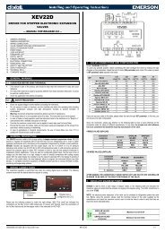
The security code is “321”.5. If the security code is correct the access to “Pr2” is enabled by pressing “SET1” on the last digit.Another possibility is the following:After switching ON the instrument, within 30 seconds, push SET1 and DOWN keys together for 3s: thePr2 menu will be entered.5.6 HOW TO MOVE A PARAMETER FROM THE “PR2” MENU TO “PR1” ANDVICEVERSA.Each parameter present in “Pr2” MENU can be removed or put into “Pr1”, user level, by pressing“SET1 + n”.In “Pr2” when a parameter is present in “Pr1” the LED is on.5.7 HOW TO CHANGE A PARAMETERTo change a parameter value operates as follows:1. Enter the Programming mode2. Select the required parameter.3. Press the “SET1” key to display its value.4. Use “UP” or “DOWN” to change its value.5. Press “SET1” to store the new value and move to the following parameter.TO EXIT: Press SET1 + UP or wait 15s without pressing a key.NOTE: the set value is stored even when the procedure is exited by waiting the time-out to expire.5.8 HOW TO LOCK THE KEYBOARD1. Keep pressed for more than 3 s the o and n keys.2. The “POF” message will be displayed and the keyboard will be locked. At this point it will bepossible only to see the set point or the MAX o Min temperature stored3. If a key is pressed more than 3s the “POF” message will be displayed.5.9 HOW TO UNLOCK THE KEYBOARDKeep pressed together for more than 3s the o and n keys, till the “Pon” message will be displayed.5.10 ON/OFF FUNCTIONTO SWITCH THE INSTRUMENT ON/OFF: If the function is enabled (par. onF=yES), by pressing theSET1 key for more than 4s the controller is switched OFF. To switch the instrument on again press theSET1 key.6. PROBES AND MEASURING RANGEProbe Down Scale Full ScaleNTC -40°C/-40°F 110°C / 230 °FPTC -50°C / -58°F 150°C / 302°FPt100 -200°C / -328°F 600°C / 1112°FTcK 0°C / 32°F 1300°C / 1999°FTcJ 0°C / 32°F 600°C / 1112°FTcS 0°C / 32°F 1400°C / 1999°F7. LIST OF PARAMETERSREGULATIONHy1 Intervention differential for set point1 (-Full Sc. / Full Sc.). It can be set with positive value orwith negative value. The kind of action depends on the S1C parameter: dir = direct or in =inverse.Hy2 Intervention differential for set point2: (-Full Sc. / Full Sc.). It can be set with positive value orwith negative value. The kind of action depends on the S2C parameter: dir = direct or in =inverse.LS1 Minimum set point1: (Down Sc.÷ Set1) Sets the minimum acceptable value for the set point1.LS2 Minimum set point2: (Down Sc.÷ Set2) Sets the minimum acceptable value for the set point2.US1 Maximum set point1: (Set1÷ Full Sc.) Sets the maximum acceptable value for set point1.US2 Maximum set point2: (Set2÷ Full Sc.) Sets the maximum acceptable value for set point2.ouC Output connections (diP=dependent; ind=independent) select if SET2 is independent fromSET1 or if the SET2 depends on SET1 (so Set2= SET1+SET2).S1C Action type output 1: S1C=in inverse action (heating/ humidifying /increase pressure); S1C=dirdirect action (cooling / dehumidifying /decrease pressure).S2C Action type output 2: S2C=in inverse action (heating/ humidifying /increase pressure); S2C=dirdirect action (cooling / dehumidifying /decrease pressure).AC Anti-short cycle delay: (0÷250 sec) Minimum time between the switching off and the followingswitching onon Minimum time a stage stays switched ON (0÷250 sec)ono: Minimum time between 2 following switching ON of the same load (0÷120 min).ALARMSALC Alarms configuration: it determines if alarms are relative to set point1 or referred to absolutevalues.rE relative to set point1; Ab absolute temperatureALL Minimum alarm:with ALC=rE: relative to set point1, (0÷|Down Sc.-Set1|) this value is subtracted from the setpoint1. The alarm signal is enabled when the temperature goes below the “SET1-ALL” value.with ALC=Ab absolute temperature, (Down Scale ÷ ALu) minimum alarm is enabled when thetemperature goes below the “ALL” value.ALU Maximum alarm:with ALC=rE: alarm relative to set point1, (0÷|Full Sc.-Set1|) Maximum alarm is enabled whenthe temperature exceeds the “SET1+ALU” value.with ALC=Ab: absolute alarm, (ALL÷Full Sc.) Maximum alarm is enabled when the temperatureexceeds the “ALU” value.ALH Temperature alarm for alarm recovery: (0,1÷Full scale) Differential for alarm reset, alwayspositive.ALd Alarm delay:(0÷999 min) time interval between the detection of an alarm condition and alarmsignalling.dAo Delay of alarm at start-up: (0÷23.5h) time interval between the detection of the alarm conditionafter instrument power on and alarm signalling.So1 Output 1 status with faulty probe: So1=oFF open; So1=on closed.So2 Output 2 status with faulty probe: So2=oFF open; So2=on closed.tbA Status of alarm relay after pushing a key. (XT121C/XT121D only): oFF = relay disabled; on =relay enabled.AS Alarm relay configuration (XT121C only): cL = 5-6 terminals open with alarm; oP = 5-6terminals closed with alarm.PROBES AND DISPLAYLCI Start of scale, only with current or voltage input: (with rES = in, dE, cE: -99.00÷199.00, withrES=irE -999÷1999) Adjustment of read out corresponding to 4mA or 0V input signal.UCI End of scale, only with current or voltage input (with rES = in, dE, cE: -99.00÷199.00, withrES=irE -999÷1999) Adjustment of read out corresponding to 20mA or 1V or 10V input signal.oPb Probe calibration: (-999÷999) allows to adjust possible offset of the probe.rES Resolution: select the resolution of the controller.in= integer (-99÷199);dEC= 1 decimal point (-99.0÷199.0),cE = 2 digits after the decimal point (-99.00÷199.00) only for current or voltage input,irE = integer, large scale (–999÷1999) only for current or voltage input.WARNING: if rES is changed from “irE” to another value, all the parameters values expressed indegrees: SET1, SET2, Hy1, Hy2, LS1,Ls2, uS1, uS2, ALL. ALu, ALH, LCi, uCi, LAo, uAo, HES,have to be checked and set.NOTE: the decimal point selection is not available on models with thermocouple input.UdM Measurement unit: it depends on models:for temperature:°C = Celsius; °F = Fahrenheit.with 4÷20mA, 0÷1V, 0÷10V input : 0= °C; 1= °F, 2= %RH, 3=bar, 4=PSI, 5=no measurementunit.PbC Probe selection: it sets the kind of probe. It depends on modelsfor temperature NTC/PTC: Ptc = PTC; ntc = ntc.for temperature standard: Pt= Pt100, J = J thermocouple, c = K thermocouple, S = Sthermocouple; Ptc = PTC; ntc = ntc.with 4÷20mA, 0÷1V, 0÷10V input : cur=4÷20mA, 0-1= 0÷1V, 10= 0÷10V.P3F Third wire presence for Pt100 probe: for using 2 or 3 wires Pt100 probes: no = 2 wires probe;yES = 3 wires probe.ANALOG OUTPUT - ONLY FOR XT120D, XT121D - OPTIONALAOC Analog output configuration: (only for models with analog output)AOC=Pb Probe reading. The analog output parameters LAO and UAO are indipendent andcorrespond to the absolute read-out probe signal.AOC=Er Probe - Set Point1. The analog output parameters LAO and UAO are related to thedifference between measurement of the probe and Set Point 1.LAO Lower analog output limit: (only for models with analog output) minimum value oftemperature associated to the 4mA analog output. This value can be absolute or relative to theSet Point 1 by setting the AOC parameter.UAO Upper analog output limit: (only for models with analog output) maximum value oftemperature associated to the 20mA analog output. This value can be absolute or relative to theSet Point 1 by setting the AOC parameter.SAO Analog output safety with probe fault: (only for models with analog output) determineswhat state the analog output should assume when the probe is faulty:SAO = oFF; analog output = 4mASAO = on; analog output = 20mA.DIGITAL INPUTHES Set point 1 changes during the Energy Saving cycle: (Down Sc./Full Sc.) sets the variation ofthe set point 1 during the Energy Saving cycle.i1F Digital input operating mode: configure the digital input function: c-H = to invert the kind ofaction: direct - reverse; oFF = to switch the controller off.; AUS = Not used; HES = EnergySaving; EAL = generic external alarm;bAL = serious external alarm: it switches offthe loads.i1P Digital input polarity:CL : the digital input is activated by closing the contact;OP : the digital input is activated by opening the contactdid Digital input alarm delay: (0÷120 min) delay between the detection of the external alarmcondition (i1F= EAL or i1F = bAL) and its signalling.OTHERAdr RS485 serial address (0÷247) identifies the instrument within a control or supervising system.onF Swithching ON/OFF enabling from keyboard: (no = disabled; yES=enabled) It permits theswitching ON/OFF of the instrument by pressing the SET1 key for more than 4s.Ptb Parameters table: (read only) Shows the code of the parameters map.rEL Software release: (read only)Pr2 To access the Pr2 parameter programming menu.8. INSTALLATION AND MOUNTINGInstrument XT120C and XT121C shall be mounted on vertical panel,in a 29x71 mm hole, and fixed using the special brackets supplied.To obtain an IP65 protection grade use the front panel rubber gasket(mod. RG-C). Instruments XT120D, XT121D, shall be mounted on anomega DIN rail .The temperature range allowed for correct operation is 0÷60 °C.Avoid places subject to strong vibrations, corrosive gases, excessivedirt or humidity. The same recommendations apply to probes. Let aircirculate by the cooling holes.9. ELECTRICAL CONNECTIONSThe instruments are provided with screw terminal block to connect cables with a cross section up to 2,5mm 2 . Before connecting cables make sure the power supply complies with the instrument’srequirements. Separate the input connection cables from the power supply cables, from the outputs andthe power connections. Do not exceed the maximum current allowed on each relay, in case of heavierloads use a suitable external relay.1592002221 XT120-121C-D GB R.1.0 24.01.2011.doc XT120C – XT121C - XT120D – XT121D 2/4
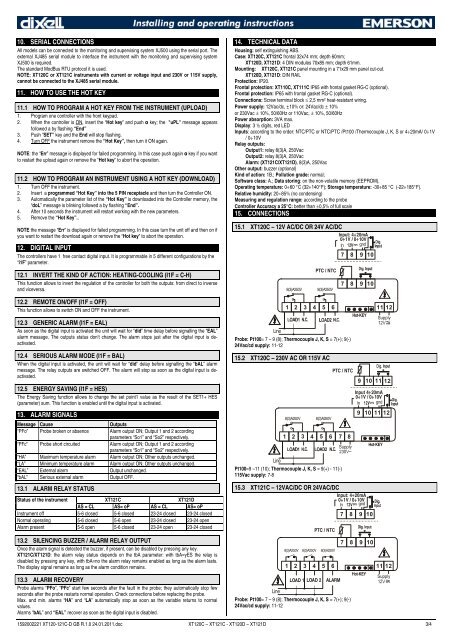
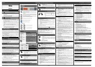
10. SERIAL CONNECTIONSAll models can be connected to the monitoring and supervising system XJ500 using the serial port. Theexternal XJ485 serial module to interface the instrument with the monitoring and supervising systemXJ500 is required.The standard ModBus RTU protocol it is used.NOTE: XT120C or XT121C instruments with current or voltage input and 230V or 115V supply,cannot be connected to the XJ485 serial module.11. HOW TO USE THE HOT KEY11.1 HOW TO PROGRAM A HOT KEY FROM THE INSTRUMENT (UPLOAD)1. Program one controller with the front keypad.2. When the controller is ON, insert the “Hot key” and push o key; the "uPL" message appearsfollowed a by flashing “End”3. Push “SET” key and the End will stop flashing.4. Turn OFF the instrument remove the “Hot Key”, then turn it ON again.NOTE: the “Err” message is displayed for failed programming. In this case push again o key if you wantto restart the upload again or remove the “Hot key” to abort the operation.11.2 HOW TO PROGRAM AN INSTRUMENT USING A HOT KEY (DOWNLOAD)1. Turn OFF the instrument.2. Insert a programmed “Hot Key” into the 5 PIN receptacle and then turn the Controller ON.3. Automatically the parameter list of the “Hot Key” is downloaded into the Controller memory, the“doL” message is blinking followed a by flashing “End”.4. After 10 seconds the instrument will restart working with the new parameters.5. Remove the “Hot Key”..NOTE the message “Err” is displayed for failed programming. In this case turn the unit off and then on ifyou want to restart the download again or remove the “Hot key” to abort the operation.12. DIGITAL INPUTThe controllers have 1 free contact digital input. It is programmable in 5 different configurations by the“i1F” parameter.12.1 INVERT THE KIND OF ACTION: HEATING-COOLING (I1F = C-H)This function allows to invert the regulation of the controller for both the outputs: from direct to inverseand viceversa.12.2 REMOTE ON/OFF (I1F = OFF)This function allows to switch ON and OFF the instrument.12.3 GENERIC ALARM (I1F = EAL)As soon as the digital input is activated the unit will wait for “did” time delay before signalling the “EAL”alarm message. The outputs status don’t change. The alarm stops just after the digital input is deactivated.12.4 SERIOUS ALARM MODE (I1F = BAL)When the digital input is activated, the unit will wait for “did” delay before signalling the “bAL” alarmmessage. The relay outputs are switched OFF. The alarm will stop as soon as the digital input is deactivated.12.5 ENERGY SAVING (I1F = HES)The Energy Saving function allows to change the set point1 value as the result of the SET1+ HES(parameter) sum. This function is enabled until the digital input is activated.13. ALARM SIGNALSMessage CauseOutputs“PFo” Probe broken or absence Alarm output ON; Output 1 and 2 accordingparameters “So1” and “So2” respectively.“PFc” Probe short circuited Alarm output ON; Output 1 and 2 accordingparameters “So1” and “So2” respectively.“HA” Maximum temperature alarm Alarm output ON; Other outputs unchanged.“LA” Minimum temperature alarm Alarm output ON; Other outputs unchanged.“EAL” External alarm Output unchanged.“bAL” Serious external alarm Output OFF.13.1 ALARM RELAY STATUSStatus of the instrument XT121C XT121DAS = CL AS= oP AS = CL AS= oPInstrument off 5-6 closed 5-6 closed 23-24 closed 23-24 closedNormal operating 5-6 closed 5-6 open 23-24 closed 23-24 openAlarm present 5-6 open 5-6 closed 23-24 open 23-24 closed13.2 SILENCING BUZZER / ALARM RELAY OUTPUTOnce the alarm signal is detected the buzzer, if present, can be disabled by pressing any key.XT121C/XT121D: the alarm relay status depends on the tbA parameter: with tbA=yES the relay isdisabled by pressing any key, with tbA=no the alarm relay remains enabled as long as the alarm lasts.The display signal remains as long as the alarm condition remains.13.3 ALARM RECOVERYProbe alarms “PFo”, “PFc” start few seconds after the fault in the probe; they automatically stop fewseconds after the probe restarts normal operation. Check connections before replacing the probe.Max. and min. alarms “HA” and “LA” automatically stop as soon as the variable returns to normalvalues.Alarms “bAL” and “EAL” recover as soon as the digital input is disabled.14. TECHNICAL DATAHousing: self extinguishing ABS.Case: XT120C, XT121C frontal 32x74 mm; depth 60mm;XT120D, XT121D: 4 DIN modules 70x85 mm; depth 61mm.Mounting: XT120C, XT121C panel mounting in a 71x29 mm panel cut-out.XT120D, XT121D: DIN RAILProtection: IP20.Frontal protection: XT110C, XT111C IP65 with frontal gasket RG-C (optional).Frontal protection: IP65 with frontal gasket RG-C (optional).Connections: Screw terminal block ≤ 2,5 mm 2 heat-resistant wiring.Power supply: 12Vac/dc, ±10% or: 24Vac/dc ± 10%or 230Vac ± 10%, 50/60Hz or 110Vac, ± 10%, 50/60HzPower absorption: 3VA max.Display: 3 ½ digits, red LEDInputs: according to the order: NTC/PTC or NTC/PTC /Pt100 /Thermocouple J, K, S or 4÷20mA/ 0÷1V/ 0÷10VRelay outputs:Output1: relay 8(3)A, 250VacOutput2: relay 8(3)A, 250VacAlarm: (XT121C/XT121D), 8(3)A, 250VacOther output: buzzer (optional)Kind of action: 1B.; Pollution grade: normal;Software class: A.; Data storing: on the non-volatile memory (EEPROM).Operating temperature: 0÷60 °C (32÷140°F); Storage temperature: -30÷85 °C (-22÷185°F).Relative humidity: 20÷85% (no condensing)Measuring and regulation range: according to the probeController Accuracy a 25°C: better than ±0,5% of full scale15. CONNECTIONS15.1 XT120C – 12V AC/DC OR 24V AC/DCInput: 4÷20mA0÷1V / 0÷10VLine8(3)A250VPTC / NTC8(3)A250V7 8 9 107 8 9 101 2 3 4 5 6 11 12Probe: Pt100= 7 – 9 (8); Thermocouple J, K, S = 7(+); 9(-)24Vac/cd supply: 11-1215.2 XT120C – 230V AC OR 115V ACLine8(3)A250V8(3)A250V1 2 3 4 5 6 7 8Pt100=9 –11 (10); Thermocouple J, K, S = 9(+) - 11(-)115Vac supply: 7-8PTC / NTCHot-KEY15.3 XT121C – 12VAC/DC OR 24VAC/DCInput: 4÷20mA0÷1V / 0÷10V8(3)A250V8(3)A250V8(3)A250V9 10 11 12Input 4÷20mA0÷1V / 0÷10V7 8 9 109 10 11 12Hot-KEY1 2 3 4 5 6 11 12LOAD 1 LOAD 2PTC / NTCALARMLineProbe: Pt100= 7 – 9 (8); Thermocouple J, K, S = 7(+); 9(-)24Vac/cd supply: 11-127 8 9 10Hot-KEY1592002221 XT120-121C-D GB R.1.0 24.01.2011.doc XT120C – XT121C - XT120D – XT121D 3/4