Innovations report - Bournemouth University
Innovations report - Bournemouth University
Innovations report - Bournemouth University

You also want an ePaper? Increase the reach of your titles
YUMPU automatically turns print PDFs into web optimized ePapers that Google loves.
INNOVATION PROJECT REPORTBy Karl Hansson BACVA3 2006<strong>Bournemouth</strong> <strong>University</strong>, UKMORPHING OF DIFFERENT TOPOLOGIESIntroduction and Background3D computer animation is today more like puppetry than drawn animation, because it is not as easyto make as good deformations in 3D as it is on papers. This makes things like cartoon animation,where extreme deformations are often required, more difficult in 3D. The problem is that 3Dmodels have a very rigid surface structure, which is defined by the amount of points it consists ofand the point connectivity, i.e. which polygon is connected to which point in order to make up thepolygons of the surface. It is very difficult to change the pointcount or the point connectivity in midanimation and especially difficult is it to do it seamlessly, since it often results in flickering orsnapping motion. In addition, the points are indexed so that each point have a unique identifierwhich is an integer ranging between 0 and pointcount – 1, this id is used to pair the point withvarious features like colour and bone influence, etc, inserting points or deleting points may causethe id of other points to change and thus distort any mapping of, for example colour. Point id alsoplays an important role when editing the model. Morphing the model in an animation requires youto either modify the current mesh or to replace the model.One can think of drawn animation as using the model replacement technique, for each new framethere is a new sheet of paper. Replacing the model in 3D animation is usually not an option since itrequires a lot of very similar models and a way to switch between these shapes to achieve smoothmotion which is not very interactive. It is more common to modify or deform a single model toachieve animation. However, modifying the geometry has its limits as well since the topology needsto remain the same. Topology in this context is how the surface is built up, how many points itconsists of and how the polygon edges are connected.Morphing between two very different shapes and being confined to a static topology description isoften unsatisfactory since the surface will have too little detail in certain areas to define both shapesequally well and too much detail in other areas where it is not needed for both models. Thetopology usually is defined parallel with the shape and the polygon edge flow and point density isusually unique to the shape.The Project ExperimentThe idea with this project is to investigate ways in which one could change the topology of anobject in mid animation and morphing between two shapes with different pointcount and pointconnectivity.The decision to tackle this problem comes from the urge to do things like morphing between shapeswith few or no commonalities in their topology, like morphing a human model into a model of acar, or to simply have things growing out of an object, for example a character who grows wings onhis back.ConceptThe basic idea was to have the different shapes being defined by hierarchies of deformers and tohave the surface and its topology automatically conforming to the deformers, thus breaking theproblem into two sub problems; deformation and adaptive subdivision. Having the shape defined bydeformers means that you could morph the influence of the different deformer sets and not thedifferent point positions, eliminating the need for the two objects to have identical pointcounts. Thesurface would then act upon the deformers and subdivide local areas that have been deformed a lot.
The system developed in this paper has been given the name Active Adaptive Surfaces or AAS.ImplementationThis project utilizes Houdini 8, which has a procedural approach to 3D, and is very suitable forexperimentations. All code is written in the VEX scripting language which is native to Houdini.The DeformerThe first requirement of the deformer is that it needs to be as light as possible in terms ofcalculation time because a shape could potentially be made up of hundreds of deformers and eachone of them needs to be evaluated at each frame. The second requirement is that the deformer has tooperate on points but without having to looking at their indices. The deformer also needs to be ableto subdivide the polygons it influences.The first approach was to make a straight forward deformer which translates a set of points in objectspace. The deformer would be represented by a plane which pulls the points towards or pushes thepoints away from it self. For the sake of the second requirement, the deformer could not use theindices of the points; it had to use some other way to select the points which it would then operateon. The optional way to pick the points without using the indices would be to select the pointswhich fulfill some requirement, such as certain location or a certain colour or normal, etc. It madesense at the time to use the normals of the object since they would update after each deformation.The idea was to sample the normal of the deformer plane and the normal of each point on thesurface and then using the dot product between these two normal vectors to get a deformation scalevalue to apply to the deformation. This value would then be clamped between 0 and 1 so that pointswith normals more than 90 degrees away from the normal of the deformer plane would get adeformation scale value of 0 which would not be deformed at all, i.e. points with normals rangingfrom perpendicular to antiparallel relative to the deformer plane normal would not get deformed atall. This worked quite well as long as the base geometry were convex, however, after severaldeformers had been applied and parts of the geometry were becoming concave the deformer wereno longer able to pick the right points to deform. Also flat parts of the geometry would getdeformed uniformly. The problem was that the deformer still evaluated all the points even thoughjust a small set of points was meant to be deformed. The deformer needed improvements to thefalloff system so that it would not simply deform points with the right normals but also to take intoconsideration other things like closeness and direction to the deformer plane center point from thesurface point.The improved version of this deformer would calculate the position of the closest point on thedeformer plane from the surface point, by taking the normalized deformer plane normal and dottingit together with the direction vector between the surface point and the deformer plane center pointand then adding the current surface point position. The closest point on the deformer plane is theposition where the surface point would end up if it had a deformation scale value of 1 (one). Thedistance from the deformer plane center point to a user defined radial threshold is used as aninterpolation reference to calculate the radial falloff. The farther away from the deformer planecenter point the lesser the influence of the deformer. The next improvement was to apply a directionfalloff by taking the dot product between the direction vector between the undeformed surface pointand the deformer plane center and the normal vector of the surface. In essence this means that if thedirection to the deformer plane center point is at an angle more than or equal to 90 degrees awayfrom the surface point normal than the deformer has no effect on that surface point. Theseimprovements made the point picking better but not perfect, there were still problems in foldedareas.
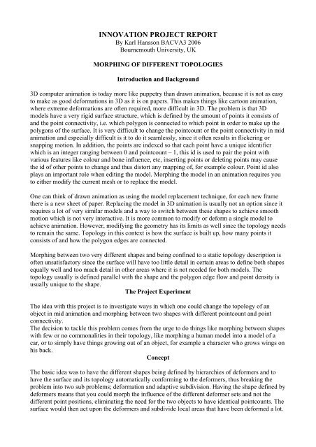
The deformer uses the vector, between the surface point and its closest point on the deformer plane, to determine thedirection of the displacement. The closest point on the deformer plane is also used to give the point a radius falloff, thefurther away from the center of the plane the point is the less influence the deformer will have on that point.The first attempt at local subdivision was simply to group the points that had been deformed morethan a certain threshold and after they had been deformed the polygons connected to those pointswould get subdivided one time. It proved, however, to be very calculation heavy and after addingjust a few deformers with subdivision to the shape Houdini would crash. This put an awkward limiton the experiment, because one could not model very much with just a few deformers.The Idea at this stage would be to have a main influence weight on each deformer and by scalingthese weights between 0 and 1 for each deformer the shape would change and with it the topologyas well. This is quite good approach because you can animate the scale factor of different deformersat a different speed, which makes the shape blending more visually interesting. One could alsoanimate the position and orientation of the deformers which would make the blending appear lesslinear. But there is practical problems with this idea as well, since there can potentially be hundredsof deformer making up one shape it would take a lot of work to set up a blend. Also editing theblend, like shifting it in time or change the pace of the blend would get very tedious. One wouldneed some kind of interface to drive the blending.Another problem at this stage was that all the deformer nodes for both shapes were connected in achain one after another. This made it difficult to maintain the deformer nodes and to identify whichnodes belonged to which shape. More ideal would be to have each shape as a separate branch of thehierarchy and then connect all of the branches into a single blending node. But at the time this didnot make much sense, because each branch would then produce separate objects, with differenttopology, and thus stepping away from the idea to blend between the deformers and not pointpositions, and one would again have to take into consideration the indices of the surface points. Thedeformers would in that case be made redundant because the objects could then just as well bemodeled using traditional tools and the blending node would be more like a regular blendshapenode that would require each object to have the same pointcount. Since the goal of this project is tofind ways to morph between shapes that have different pointcounts and different connectivity, thefeature of having the different branches connect up to one blending node seemed impossible.
Base ObjectDeformer Shape AInfluence weight a1SubdivisionDeformer Shape BInfluence weight b1SubdivisionDeformer Shape AInfluence weight a2SubdivisionDeformer Shape BInfluence weight b2SubdivisionResulting shapeThe first version of the system looked like this. It’s a very basic approach which has just one long chain of deformernodes and not separate branches for the different shapes. The blending was achieved by scaling the influence weightsbetween 0 and 1. For example, to show shape A one would set the weights a1 and a2 to 1 and b1 and b2 to 0. To showshape B one would set the weights a1 and a2 to 0 and b1 and b2 to 1. And to blend them one would interpolate bothshapes weights so that their sum adds up to 1.The BlenderOne feature of polygon surfaces is that one can map attributes to the points on the surface, theseattributes would typically be things like colour, texture, bone weights, etc. If an attribute is mappedout on a polygon surface and if the surface is then subdivided, the new points generated from thesubdivision will also have the attribute and the value of the attribute for these new points will fitinto the mapping. For example, two points sharing a polygon edge have attribute w=0 and w=1respectively, if then the edge is divided into two edges; there will be a new point in between the twoold points. This new point will have the attribute value w=0.5, i.e. the average of the two old points.Houdini makes it possible for the user to make custom point attributes; a feature which was veryuseful for taking the project to the next level.A demonstration of how point attributes are mapped after subdivision. The new points on the surface will get anaverage attribute value relative to the surrounding points.The way a blendshape function usually works, is that it moves the points of the geometry towardsthe location of the same point, with the same index number, in another shape. That is why theseshapes usually need to have the same number of points. It is a very difficult to blend two shapeswith different topology and there is no real good solution today.What if one could store the deformation as an attribute on each point without actually deforming thesurface at the deformer? The idea might seem strange but it makes sense when it comes to blending
the deformers. It is basically a matter of changing the order in which things are happens. Thedeformer would still have the role of deforming and defining the geometry but on a more indirectlevel. Since the two shapes comes from the same base geometry and the deformers haven’tphysically changed or added any points to the geometry before the blender, the two shapes willhave the same pointcount and the same connectivity, but the two shapes will carry differentdeformation descriptions in their points attributes. The blender would now have a slightly differentrole; it will not blend the point positions of the two shapes as is normal, but rather blend thedeformation attributes.The next step was to solve the subdivision problem, since the idea of this improvement was to havethe blender work on separate shapes branches of the hierarchy, there could not be any subdivisionbefore the blender so it have to happen after. The question now was; where on the geometry shouldthe subdivision be applied? One could group points, in the blender node, that has been deformedmore than a certain threshold and subdivide the polygons in direct connection with those points.Developing on this idea, the decision of which points to add to the subdivision group would be donein the deformer rather than in the blender. This also made it possible to have more than onesubdivision group in order to have several iterations of subdivisions, which is useful when someareas are deformed so much that only one subdivision level would not be enough to maintain thelevel of detail. Another point attribute was then added which stores an integer number that reflectsthe number of times the polygons sharing that point would get subdivided. Each deformer checkswhether a point is deformed more than a user specified threshold and if so; the subdivision attributeis incremented by one.In Houdini there are some restrictions where one cannot, in a subdivision node, change divisionlevel on per face basis, for example, it is not possible, in a single subdivision node, to subdivide oneface to the level 1 and another face to the level 3, for this you would need to have two subdivisionnodes. In order not to get too many subdivision nodes, for the sake of performance, a maximumlimit of subdivision levels was set to 3, which was fine for this project, but is probably not enoughfor regular content creation.In the blender node, after the blending had taken place, the points which are to be subdivided areput into three groups according to their subdivision attribute, i.e. points with a subdivision value of1 is put in group 1 and points with subdivision value of 2 is put in group 2 and so on. These pointgroups are then converted to polygon groups and fed into one of three subdivision nodes followingthe blender node. Because the subdivision needs to happen after the blending node but before thephysical deformation, a separate build node needs to be created to handle the deformation.The build nodeThe final node handles the physical deformation; it is at this point the base object is turned into theshape that is the result of all the deformers and the blending node. This node simply displaces eachpoint according to its deformation attribute and because of the automatic attribute mapping, the newpoints, generated from the subdivision, also has a deformation attribute and they are displaced aswell.
Base ObjectDeformer Shape ADeformer Shape BDeformer Shape ADeformer Shape BDeformer Shape ADeformer Shape BBlenderSubdivision x3BuildThe last version of the system is more advanced. The two shapes are defined in separate branches which feed into theblending node. Note that there are no subdivisions happening before the blender which means that the two shapes willhave the same pointcount. When the two shapes have been blended the geometry will be sent to the subdivision wherethe appropriate faces will be subdivided. Finally the build node will displace the points resulting in the final shape.Further improvements to the deformerThe system was working quite well; it morphed between to different shape which effectively, in theend, had different pointcount, but there were also problems with the way the deformers worked. Thedeformers used the normals of the base object to select the points to operate on and the deformationof a point could only happen in a direction no more than 89 degrees angle from the normal, and atthat an angle the deformation would be minimal because of the deformation falloff. This meant thatthe point of reference were always the same and direction of the deformation was also limited toroughly the same direction, which in turn mean that you could only model things coming straightout of the base object or going into the base object. Curved shapes were almost impossible tomodel. It was clear that some other way of selecting and deforming points were needed.Sphere of influenceInstead of using the normals of the base object as a reference, it made sense to use some kind ofinfluence object. The influence object is just a point in space that is represented by a sphere and theradius of the sphere represents the falloff range of influence. Any surface point outside the spherewould not be influenced and any point inside the sphere would have a weighted influencedepending on how far from the center of the sphere it is. This is a more interactive way ofcontrolling which points to operate on and it also means that you can work on the deformation datadirectly and not on the physical point of the base object. For example, a point on the base object hasthe location a = [a x , a y , a z ], and the deformation attribute b =[b x ,b y ,b z ] which may be some placedifferent in the 3D space, the influence object have to be placed with respect to the deformation band not a. In Houdini you can edit the deformers early on in the hierarchy and at the same time sewhat the final output looks like, this makes it very easy and interactive to place the influence objectin the right position. This also means that the deformer are now using the influence object asreference and not the normal and there is no longer a limit in which direction the deformation canbe applied and as a result there is no longer a problem to make bendy shapes.Analyzing the outcome of this projectTo visualize this whole system using a metaphor of a house building process, one can think of thedifferent deformer branches in the shape hierarchy, as teams of architects that defines the differentshapes, they only describe the shape and how much material to use as blueprints. The blender canbe thought of as the house buyer who picks features from the different architect teams. And the final
uild node can be thought of being the construction firm delivering the final house.It is quite hard to model anything recognizable using this system. Part of the problem is that thedeformers are very basic and can be improved further with better control of falloff. The majorproblem, however, with this system is the subdivision, optimally the subdivision should happen atthe deformer in order to keep sufficient detail to model with, for performance reasons as well as forthe sake of the blending this is not possible at this stage, it is an area which deserves more research.The fact that the subdivision happens after all of the deformation can result in some very uglyartifacts.Other SolutionsAs was said before there are no real good solution to morphing between shapes with differenttopologies, but there are some interesting research going on in this area.One of the most interesting and perhaps controversial ideas is that of point surfaces. A big hurdle toovercome is that the mesh geometry needs to maintain some kind of connectivity between thepoints, adding new points you can do with subdivision but to change the connectivity between thepoints to get the optimal topology description is quite hard and very inefficient. One solution to thisproblem would be to not having any mesh to worry about. The very interesting siggraph paper,“Shape Modeling with Point-Sampled Geometry“ [Mark Pauly, Richard Keiser, Leif P. Kobbelt,Markus Gross] describes the implementation and use of point surfaces. Point surfaces are quitesimply surfaces that are made up of points but without a mesh which is more commonly related tothe areas of 3D scanning. Each point is the center of a circle primitive which in the surface slightlyoverlaps each other in order to give the impression of being a continuous surface. The lack of meshis a unique feature that would suit the areas of shape morphing very well. In their paper, ShapeModeling with Point-Sampled Geometry, Mark Pauly and his colleagues describe a techniquewhere points are scattered over a regular polygon of parametric NURBS surface, the points thenuses information of the underlying surface to map out normals, colour and texture etc. The pointsurface can then be further deformed using various sculpting tools, and the surface is thenmaintained using a moving least square algorithm. In essence this becomes like a super elastic skinwhich inserts or deletes point primitives in order to maintain the surface density. The drawback tothis system is that the surface appears slightly grainy or blurry when rendered, but that might besubject to future render enhancements.Another way to blend between two different shapes might be to use metaball surfaces, it’s atechnique that has been around for a long time and is probably the best way of dealing with shapeshifting. It is, however, not very easy to model with metaballs they have, especially when it comesto model fine detail.ConclusionMorphing shapes with different topologies is a very complex problem, it involves not only changingthe shape of the geometry but the topology also needs to change. Mesh topologies are very rigid andbecause there can be an infinite number of different meshes and the requirement of each meshmight be different, one cannot easily construct an algorithm that changes the topology for any mesh.This project explores the idea of having the surface subdividing it self to meet the requirements ofdifferent sets of deformer. It is an idea of having the surface topology conforming to the modelingtools, and to have the modeling tools defining the shape rather than to have point positions definingthe shape. The surface system developed in this project does not, however, change the pointconnections, it merely uses existing subdivision tools to add extra detail where needed. This is notoptimal since it makes a very ugly topology which deforms quite badly, but for this experiment itwas good enough to show that the shape blending system works. With the shape and the topologybeing defined by the modeling tools, i.e. the deformers, one can scale the influence of differentdeformers to change the topology as well as the shape.
References:Alan H. BarrGlobal and local deformations of solid primitivesACM 0-89791-138-5/84/007/00211984Computer Science DepartmentCalifornia Institute of TechnologyPasadena CaliforniaMark Pauly, Richard Keiser, Leif P Kobbelt, Markus GrossShape Modeling with Point-Sampled GeometryACM 0730-0301/03/0700-06412003Anders Adamson, Marc AlexaAnisotropic Point Set SurfacesACM 1-59593-288-7/06/00012006Department of Computer ScienceTU Darmstadt
Appendix A:The accompanying movie files found in the movies folder:AAS001.aviAAS002.aviAAS003.aviAAS004.aviAAS005.aviAAS006.aviMetaball.aviShows the first successful blend between one shape defined with three deformers and anothershape defined by six deformers. It also shows what happens when the base object is rotatedbefore the deformers.The same blend as in AAS001, here displaying pointcount.Shows the first successful test which results in a bended shape using the sphere of influence.Shows the first attempt to model something recognizable with this system. This is a nose.Shows the second attempt to model something recognizable. A shape blend between a humanhead and a eagle head. Pointcount displayedShows the final attempt. A much more detailed head and a eagle head is blended. Also showswhat happens if the deformers are moved around in order to get non linearity.Pointcount is shown.A metaball model was created to se how easy it is to model with metaballs.Appendix B:Vex code files:aas.vexaasGD2.vexaasBuild.vexThe latest vex code for the blender nodeThe latest vex code for the deformer node.The latest vex code for the build node.Scene files:The latest and most complete scene file is the AAS007.hip.Otl files:The otl file AAS2.otl holds the latest aas operators for Houdini.