
Create successful ePaper yourself
Turn your PDF publications into a flip-book with our unique Google optimized e-Paper software.
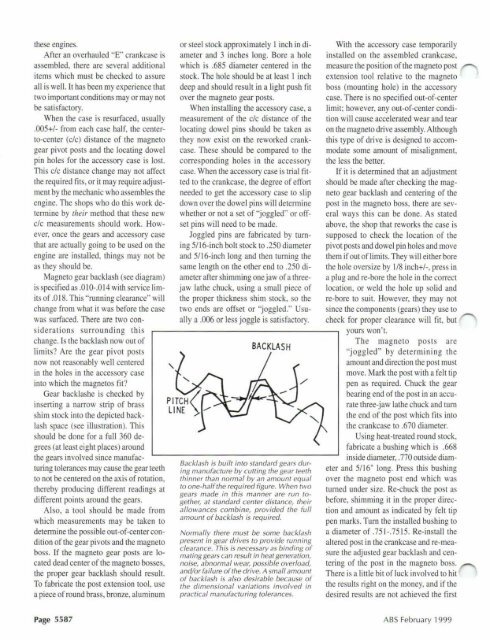
these engines.After an overhauled "E" crankcase isassembled, there are several additionalitems which must be checked to assureall is well. It has been my experience thattwo imponant conditions mayor may notbe satisfactory.When the case is resurfaced, usually.005+1- from each case half, the centerto-center(c/c) distance of the magnetogear pivot posts and the locating dowelpin holes for the accessory case is lost.This clc distance change may not affectthe required fits, or it may require adjustmentby the mechanic who assembles theengine. The shops who do this work detennineby their method that these newclc measurements should work. However,once the gears and accessory casethat are actually going to be used on theengine are installed, things may not beas they should be.Magneto gear backlash (see diagram)is specified as .010-.014 with service limitsof.O 18. This "running clearance" willchange from what it was before the casewas surfaced. There are two consideratio ns surrounding thi schange. Is the backlash now out oflimits ? Are the gear pivot postsnow not reasonably well centeredin the holes in the accessory caseinto which the magnetos fit?Gear backlashe is checked byinserting a narrow strip of brassshim stock into the depicted backlashspace (see illustration ). Thisshould be done for a full 360 degrees(at least eight places) aroundthe gears involved since manufacturingtolerances may cause the gear teethto not be centered on the axis of rotation,thereby producing different readings atdifferent points around the gears.Al so, a tool should be made fromwhich measurements may be taken todetennine the possible out-of-center conditionof the gear pivots and the magnetoboss. If the magneto gear posts are locateddead center of the magneto bosses,the proper gear backlash should result.To fabricate the post extension tool , usea piece of round brass, bronze, aluminum"or steel stock approximately I inch in diameterand 3 inches long. Bore a holewhich is .685 diameter centered in thestock. The hole should be at least I inchdeep and should result in a light push fitover the magneto gear posts.When installing the accessory case, ameasurement of the clc di stance of thelocating dowel pins should be taken asthey now exist on the reworked crankcase.These should be compared to thecorre sponding holes in the accessorycase. When the accessory case is trial fittedto the crankcase, the degree of effortneeded to get the accessory case to slipdown over the dowel pins will determinewhether or not a set of "joggled" or offsetpins will need to be made.Joggled pins are fabricated by turningSlI6-inch bolt stock to .250 diameterand 5116-inch long and then turning thesame length on the other end to .250 diameterafter shimming one jaw of a threejawlathe chuck, using a small piece ofthe proper thickness shim stock, so thetwo ends are offset or "joggled." Usuallya .006 or less joggle is satisfactory.BACKLA SHBacklash is built into standard gears duringmanufacture by cutting the gear teeththinner than normal by an amount equalto one-half the required figure. When twogears made in this manner are run together,at standard center distance, theirallowances combine, provided the fullamount of backlash is required.Normally there must be some backlashpresent in gear drives to provide runningclearance. This is necessary as binding ofmating gears can result in heat generation,noise, abnormal weal:, possible overload,and/or failure of the drive. A small amountof backlash is a/50 desirable because ofthe dimensional variations involved inpractical manufacturing tolerances.With the accessory case temporarilyinstalled on the assemb led crankcase,measure the position of the magneto postextension tool relative to the magnetoboss (mounting hole) in the accessorycase. There is no spec ified out-of-centerlimit; however, any out-of-center conditionwill cause accelerated wear and tearon the magneto dri ve assembly. Althoughthis type of drive is designed to accommodatesome amount of misalignment.the less the better.If it is determined that an adjustmentshould be made after checking the magnetogear backlash and centering of thepost in the magneto boss, there are severalways thi s can be done . As statedabove, the shop that reworks the case issupposed to check the location of thepivot posts and dowel pin holes and movethem if out of limits. They will either borethe hole oversize by 1/8 inch+/-, press ina plug and re-bore the hole in the correctlocation , or weld the hole up solid andre-bore to suit. However, they may notsi nce the components (gears) they use tocheck for proper clearance will fit, butyours won't.The magneto po sts are"joggled" by determining th eamount and direction the post mustmove. Mark the post with a felt tippen as requ ired. Chuck the gearbearing end of the post in an accuratethree-jaw lathe chuck and tumthe end of the post which fits intothe crankcase to .670 diameter.Using heat-treated round stock,fabricate a bushing which is .668inside diameter, .770 outside diameterand S1I6" long. Press this bushingover the magneto post end which wasturned under size. Re-chuck the post asbefore, shimming it in the proper directionand amount as indicated by felt tippen marks. Turn the installed bushing toa diameter of .751-.7515. Re-install thealtered post in the crankcase and re-measurethe adjusted gear backlash and centeringof the post in the magneto boss.There is a little bit of luck involved to hitthe results right on the money, and if thedesired results are not achieved the firstPage 5587ABS <strong>February</strong> <strong>1999</strong>