

(VRC) 321 Radio Set - VMARSmanuals
(VRC) 321 Radio Set - VMARSmanuals
(VRC) 321 Radio Set - VMARSmanuals

You also want an ePaper? Increase the reach of your titles
YUMPU automatically turns print PDFs into web optimized ePapers that Google loves.
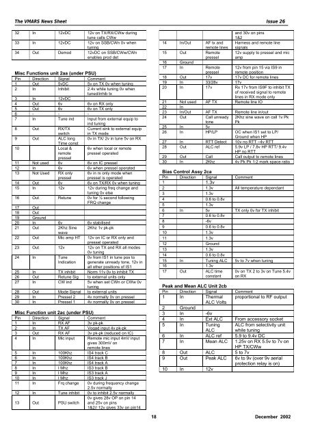
The VMARS News Sheet Issue 2632 In 12vDC 12v on TX/RX/CWw duringtune calls CWw33 In 12vDC 12v on SSB/CWn 0v whentuning34 Out Demod 12vDC on SSB/CWw/CWnenables prod detMisc Functions unit 2aa (under PSU)Pin Direction Signal Comment1 Out 5vDC 5v on TX 0v when tuning2 In Inhibit 2.4v while tuning 0v whentuned/inhib tx3 In 12vDC4 Out 6v 6v on RX only5 Out 6v 6v on TX only6 - - -7 In Tune ind Input from external equip toind tuning8 Out RX/TXswitchCurrent sink to external equipin TX mode9 Out ALC longTime const0v in TX/ 2v in tune 5v on RX10 Local &remotepressel6v when local or remotepressel operated11 Not used 6v 6v on IC pressel12 In 6v 6v when pressel operated13 Not Used RX onlypressel6v in rx only mode whenpressel is operated14 Out 6v 6v on TX/RX 0v when tuning15 In 12v 12v during freq change andtuning 0v else16 Out Retune 0v for ½ second followingFRQ change17 Out18 Out19 Ground20 In 6v 6v stabilised21 Out 2Khz Sine 2Khz 1v pk-pkwave22 Out Mic amp HT 12v on IC or RX only andpressel operated23 Out 12v 12v on TX and RX all modes0v tuning24 In TuneIndication0v from IS1 in tune pos togenerate unready tone, 12v inall other positions of IS125 In TX inhibit Norm 11v 0v to inhibit TX26 Out Retune Sig to external units only27 In CW ind 5v when set CWn or CWw 0vtuning28 Out Mode Signal to external units29 In Pressel 2 4v normally 0v on pressel30 In Pressel 1 4v normally 0v on presselMisc Function unit 2ac (under PSU)Pin Direction Signal Comment1 In RX AF 3v pk-pk2 In TX AF Vogad input 4v pk-pk3 Out RX AF 3v pk-pk (reduced on IC)4 In Mic input Remote mic input 4mV inputgives 300mV onremote lines5 In 100Khz IS4 track C6 In 100Khz IS4 track B7 In 100Khz IS4 track A8 In I Mhz IS3 track B9 In I Mhz IS3 track A10 In I Mhz IS3 track J11 In Frq change 0v during frequency change2.5v normally12 In Tune inhibit 0v to inhibit 2.5v normally13 Out PSU switch0v gives 28v OP on pin 14and 25v on pins1&2// 12v gives 33v on pin14and 30v on pins1&214 In/Out AF tx andremote linesHarness and remote linesignals15 Out Remotepressel12v supply to pressel and micamp16 Ground17 In Remotepressel12v from pin 15 via IS9 inremote position18 Out 17v 17v DC for remote lines19 In 33/28v 17v20 In 17v Rx 17v from IS9F to inhibit TXof received signal to remotelines in RX mode only21 Not used AF TX Remote line IO22 In23 In/Out AF TX Remote line in/out24 Out Call unreadytone2Khz sine wave on call 1v PkPk25 In 5v26 In HP/LP OC when IS1 set to LP/Ground when HP27 In RTT Detect 10v no RTT –4v RTT28 Out ALC ref 5.9v LP / 7.8v HP RTT/ 9.4vHP no RTT29 Out Call Call output to remote lines30 In 2Khz 4v Pk Pk 1:2 mark space ratioBias Control Assy 2caPin Direction Signal Comment1 1.3v2 1.3v All temperature dependant3 1.3v4 0.6 to 0.8v5 1.3v6 In 5v TX only 0v for TX inhibit7 0.6 to 0.8v8 -6v9 0.6 to 0.8v10 1.3v11 1.3v12 Ground13 1.3v14 0.6 to 0.8v15 In Tuning ALC 5v to 7v when tuning16 1.3v17 Out ALC timeconstant0v on TX 2 to 3v on Tune 5.4von RXPeak and Mean ALC Unit 2cbPin Direction Signal Comment1 In Thermal proportional to RF outputALC Volts2 Ground3 In -6v4 In Ext ALC From accessory socket5 In TuningALCALC from selectivity unitwhile tuning6 In ALC ref 5.9 to 9.4v DC7 In Mean ALC 1.25v on RX 5.5v to 7v onHP TX/CWw8 Out ALC 5 to 7v9 Out Peak ALC 6v to 9v (over 9v aerialprotection relay is on)10 In 12v18 December 2002


