Download specification
Download specification
Download specification

You also want an ePaper? Increase the reach of your titles
YUMPU automatically turns print PDFs into web optimized ePapers that Google loves.
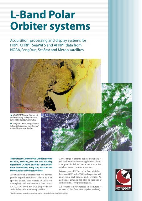
L-Band Polar Orbiter systems applications➐ HRPT image received from the NOAA 12satellite on 10th July 1996, showingHurricane Bertha over the Bahamas➐ Scrubland in Brazil, between the Marapi andParu de Oeste rivers, is clear on this HRPT imageWeather system observationThe multi-spectral HRPT image opposite (bands 1, 2 and 4) showsHurricane Bertha near Eleuthera in the Bahamas. As well astracking hurricanes and storms, HRPT and CHRPT data can beused to study weather systems and determine cloud types,temperatures and sizes.The TOVS data received by the system can be used, for example, tolook at geostrophic wind fields at different altitudes, produce T-Φand T-log(P) tephigrams and plot ozone mappings, using thirdpartysoftware (such as PC-TOVS or University of Wisconsin ITPP).Environmental monitoringGreen vegetation has a reflectance of up to 60% in the near infra-redband. The data from the band 2 (near infra-red) sensor cantherefore be applied to the green plane of a multi-plane image toshow green vegetation.The magnified area of the image opposite shows a largearea of scrubland in Brazil. This is indicated by thebrown colour, caused by the low vegetation activitycompared with the surrounding areas.Sea surface temperaturesThe image below left is a McClain SST (sea surfacetemperature) product generated by the Dartcom iDAP displayand processing software. It was produced from bands 2 (near infrared),4 and 5 (both thermal infra-red) of an HRPT image of themouth of the River Plate, between Uruguay and Argentina. It wastransformed to fit a Mercator projection, and a mask was applied toobscure the land, which is not relevant in an SST product.The image clearly shows currents, boundaries between areas ofdifferent sea surface temperature and mixing of warm and coldwater. The temperature of each pixel in the image can be obtainedto an accuracy of 0.1˚C.SST products can be used to determine likely areas of fish feeding.Also, knowing the exact location and direction of travel of warm andcold currents can be vital in route planning to help reduce fuelconsumption and voyage times.Ocean colourFeng Yun CHRPT images contain five more bands than HRPTimages. Three of these are ocean colour, which enable features suchas the algal bloom in the image below to be detected. The image is acolour composite of bands 1, 2 and 8 of a Feng Yun 1C CHRPTimage, and has been enhanced using the Dartcom iDAP software.The areas of algal bloom (purple and magenta) are clearly visible.➐ A McClain SST product (Mercator-reprojectedwith land masking) showing sea surfacetemperatures and currents❿ Areas of algal bloom off the coast of South-West England on an enhanced CHRPT image
Vegetation indexingThe image opposite was produced using the Dartcom iDAPsoftware, and shows Spain and Portugal. It is a NormalisedDifference Vegetation Index (NDVI) product, and was generatedusing the following formula:(band 2 – band 1) ÷ (band 2 + band 1) × 255This shows the vegetation activity over the land area. The higherthe NDVI value, the more active the vegetation.The image has been transformed to fit a Mercator projection andareas of sea have been removed from the image with a user-definedmask. All of this processing can be accomplished using the theDartcom iDAP software, which includes a comprehensive formulalanguage for product generation and Digital Elevation Model (DEM)masking facilities for land and sea masking.Third-party image processingIn addition to a wide range of image processing facilities, theDartcom iDAP viewing and processing software also provides fileformat outputs to enable further processing in a number of widelyusedthird-party image processing applications, such as PCIGeomatica, ERDAS Imagine and ENVI * . NOAA level 1B and SHARPlevel 1B outputs are also available to allow importing of data intoother processing packages, such as Space 2.The multi-spectral image opposite(magnification inset) shows approximatelythe same area as the SST product above(the mouth of the River Plate). It wasexported to PCI Geomatica formatfrom iDAP, then processed to showsuspended sediment at the mouth ofthe river. The image shows a clearboundary between the sea (blue) andthe sediment (magenta).Cloud classificationThe image below right was produced froman HRPT image of Western France using PCIGeomatica. It is a cloud classification using acluster analysis. The water and land areas were maskedout and an unsupervised classification was carried out to identifyup to eight cloud classes.The results were thenexamined and labels assignedto each class, basedCloud classification legendWaterupon interpretation andreference to a cloud chartLandgiving the temperatureranges and brightnessFog (low cloud)values in bands 1 and 2.Thin Stratos cloudWhere appropriate, twoclasses were merged soLow Stratocumulusthat the final classificationMedium Stratocumuluscontains only six classes,plus land and water.* PCI Geomatica, ERDAS Imagineor ENVI optional at extra cost.NimbusNimbus➐ A normalised difference vegetation index(NDVI) product generated using the DartcomiDAP software, showing vegetation activity➐ An HRPT image processed using PCIGeomatica software to show suspendedsediment at the mouth of the River Plate➐ A cloud classification produced using PCIGeomatica software, enabling cloud classes to beidentified quickly and easily
L-Band Polar Orbiter systems technical details➐ Clockwise from top left: 1.8m antenna androtator, 1.5m antenna and rotator inside radome,1.2m antenna and rotator, 1.3m active-stabilisedmarine antenna➐ Receiver rack fitted with two multi-modedigital receivers and LRIT USB interface module➐ Dartcom HRPT/CHRPT Grabber software (left),Dartcom iDAP and MacroPro software (right)AntennaA wide range of antennas is available to suit land-based and marineapplications. The 1.8m, 1.5m and 1.2m parabolic dish and rotatorare designed for fixed, land-based ground stations.The 1.3m active-stabilised marine antenna uses a state-of-the-artactive stabilisation system and is enclosed in a radome.These options all provide reliable, high-quality data and are capableof HRPT, CHRPT, SeaWiFS, AHRPT, LRD and LRIT reception.Receiver rackThe receiving equipment is housed in a 84HP Eurocard rack (deskor rack mount) containing plug-in modules:• Multi-mode receivers and LNB power supplies module containingup to two digital multi-mode receivers (one as standard).• HRPT/CHRPT/SeaWiFS USB interface module.• AHRPT/LRD USB interface module.• Optional LRIT USB interface module.• USB hub and serial communications module containing 7-port USBhub, four USB serial adaptors and RS232/422/485 rotator interface.• GPS receiver module.• Switch mode rack power supply module.Satellite data is transferred to the host computer via a 12Mbit/s USBconnection. GPS data is transferred via RS232 and rotator controldata via RS232/422/485, or optionally via USB if serial ports are notavailable on the host computer.Host computerThe exact <strong>specification</strong>s of the host computer can be tailoredaccording to your requirements. Suggested <strong>specification</strong>s are:• Desktop or notebook PC with dual-core processor.• PCI Express graphics with 128MB RAM.• 19” TFT display (15” for notebooks).• 1GB RAM.• 80GB+250GB hard disk drives (single 160GB for notebooks).• DVD±RW drive.• 10/100Mbit Ethernet for data output and remote archiving.• Windows XP Professional.Software• Dartcom HRPT/CHRPT Grabber software, providing automaticimage capture, archiving, decommutation and exporting.• Dartcom iDAP software, providing a comprehensive range ofdisplay, manipulation, processing and printing facilities.• Dartcom MacroPro software which automates the powerfulprocessing facilities provided by iDAP.Dartcom, Powdermills, Postbridge, Yelverton, Devon, PL20 6SP, UKTelephone (01822) 880253 • International +44 1822 880253Fax (01822) 880232 • International +44 1822 880232Internet http://www.dartcom.co.ukE-mail sales@dartcom.co.ukCopyright © 2007 Dartcom. Dartcom reserves the right to change <strong>specification</strong>s without notice. Pictures are for illustrative purposes only.Correct from 6th September 2007. E&OE.
L-Band Polar Orbiter systems marine antenna➐ Equipment rackinstalled on Oden➐❷ Dartcom 1.3m active-stabilised marineantenna installed on the Swedish Polar Instituteicebreaker Oden1.3m active-stabilised marine antennaThe Dartcom 1.3m active-stabilised marine antenna is capable oftracking NOAA, Feng Yun, SeaStar, Metop and NPOESS polarorbitingsatellites on-board moving vessels.The antenna uses a state-of-the-art X-Y pedestal to compensate forthe pitch, roll and yaw of the vessel. It provides continuous axismovement, eliminating cable wrap problems without the need forslip-rings or rotary joints. Together with the pedestal’s very highspeed and accuracy, this also ensures that there is no “cone ofsilence”, even during overhead passes.The antenna control unit is located below decks in a 19” rack withthe receiving equipment and rack-mount computer. It providesfully-automatic control of the X-Y pedestal using an advancedstabilisation algorithm. Full diagnostics and maintenance tools areavailable via a graphical user interface on a TFT colour display.When not ingesting polar-orbiter data, options are available whichallow the reception of LRIT data from geostationary satellites (suchas MSG direct broadcast, GOES and MTSAT) or Ku-band satelliteTV transmissions (in conjunction with a suitable receiver).Features• 1.3m parabolic dish antenna.• 1.7GHz L-band RHC feed, pre-LNA filter and LNA unit.• High-speed, high-accuracy, high-reliability XY pedestalcompensating for pitch, roll and yaw, with continuous axismovement to eliminate cable wrap problems.• Weather-tight glass fibre radome and base, with access hatch.• Fully-automatic antenna control unit with full diagnostics andmaintenance tools provided via a TFT colour display and GUI.• Below-decks equipment mounted in a 19” rack.• Bit error rate of better than 1:10 6 from 3.5˚ elevation for HRPT,AHRPT and LRD, 5˚ for SeaWiFS and 7.5˚ for CHRPT.• System G/T of 3.4dB/K at 5˚ elevation.• Designed to meet MIL-STD <strong>specification</strong>s.• ISO9001/CE certified.Antenna:DiameterPolarisationGainPedestal:StabilisationAzimuth rangeElevation rangePitch rateRoll rateYaw rateTurn rateTotal weight1.3mL-band right-hand circular24.7dBiCActive, with gyro sensors forpitch, roll and yaw ratesNo limit (continuous)–10˚ to 190˚±15˚ in 6 seconds±30˚ in 8 seconds±80˚ in 50 seconds10˚/second150kg (approximately)Radome:HeightDiameterEnvironment:Operational wind speedSurvival wind speedOperating temperatureDesign <strong>specification</strong>s:EMI/RFIVibrationShockPower requirements:VoltagePower consumption1.68m (approximately)1.52m (approximately)185km/h (100 knots)240km/h (130 knots)–30˚C to +70˚CMIL-STD-461MIL-STD-167-1MIL-STD-901115/230V AC @ 50/60Hz1000VA (typically)
L-Band Polar Orbiter systems receiver rackThe receiver rack can be supplied with up to two state-of-the-artdigital multi-mode receivers to provide support for HRPT, CHRPT,SeaWiFS, AHRPT and LRIT. With an additional antenna andsoftware simultaneous reception is also possible from two types ofservice (HRPT/CHRPT/SeaWiFS and LRIT, for example).The rack can be upgraded in the future to support LRD data fromNPOESS satellites (when available).Features• 19 inch 4U high Eurocard rack.• Plug-in modules for easy maintenance and upgrades.• Desk or rack mount.• 12Mbit/s USB connection for satellite data and rack control.• RS232 for GPS data and RS232/422/48 for rotator control, oroptionally via USB if serial ports are not available.ModulesThe receiver rack contains the following plug-in modules:• Multi-mode receivers and LNB power supplies module containingup to two digital multi-mode receivers (one as standard).• HRPT/CHRPT/SeaWiFS USB interface module.• AHRPT/LRD USB interface module.• Optional LRIT USB interface module.• USB hub and serial communications module containing a 7-portUSB hub, four USB serial adaptors and an RS232/422/485 rotatorinterface.• GPS receiver module.• Switch mode rack power supply module.➐ Receiver rack fitted with two digital multimodereceivers and LRIT USB interface moduleDemodulationDecodingIF conversionOperating temperatureStorage temperatureHumidityEMCElectrical safetyDimensions (W×H×D)WeightPower requirementsPower consumptionWild heat➐ Specifications of receiver rack fitted with twodigital multi-mode receivers and LRIT USBinterface moduleQPSK, BPSK, PSK, up to 3.5MSPSViterbiDirect 70MHz, up to 50MSPS,10-bit resolution0˚C to +50˚C0˚C to +70˚C30% to 70% non-condensingBS EN 6100-6-4:2001LVD 73/23/EEC as amendedby 93/68/EEC450×180×455mm (includingconnector projections)14.5kg (approximate)110–240V AC @ 50–400Hz60VA100W