A theta (1) algorithm for modulo addition ... - khaledelleithy.org
A theta (1) algorithm for modulo addition ... - khaledelleithy.org
A theta (1) algorithm for modulo addition ... - khaledelleithy.org

You also want an ePaper? Increase the reach of your titles
YUMPU automatically turns print PDFs into web optimized ePapers that Google loves.
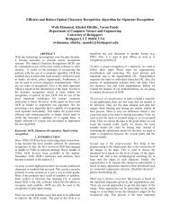
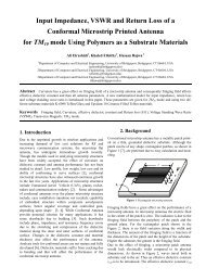
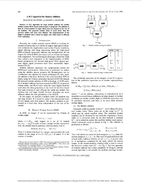
628IEEE TRANSACTIONS ON CIRCUITS AND SYSTEMS, VOL. 37, NO. 5, MAY 1990A O(l) Algorithm <strong>for</strong> Modulo AdditionKHALED M. ELLEITHY AND MAGDY A. BAYOUMIAbsfrad -A O(l) <strong>algorithm</strong> <strong>for</strong> large <strong>modulo</strong> <strong>addition</strong> <strong>for</strong> residuenumber system (RNS) based archictectures is proposed. The <strong>addition</strong> isdone in a fixed number of stages which does not depend on the size ofthe modulus. The proposed <strong>modulo</strong> adder is much faster than theprevious adders and more area efficient. The implementation of theadder is modular and is based on simple cells which leads to efficientVLSI realization.I. INTRODUC~IONRecently, the residue member system (RNS) is receiving increasedattention due to its ability to support high-speed concurrentarithmetic [ 11. Applications such as fast Fourier trans<strong>for</strong>m,digital filtering, and image processing utilize the high-speedRNS arithmetic operations; <strong>addition</strong> and multiplication, do notrequire the difficult RNS operations such as division and magnitudecomparison. The technological advantages offered by VLSIhave added a new dimension in the implementation of RNSbasedarchitectures [2]. Several high-speed VLSI special purposedigital signal processors have been successfully implemented[31-[51.Modulo <strong>addition</strong> represents the computational kernel <strong>for</strong>RNS-based architectures. Subtraction is per<strong>for</strong>med by addersusing the additive inverse property [6]. Multiplication can betrans<strong>for</strong>med into <strong>addition</strong> by several techniques [7]. Also, <strong>modulo</strong><strong>addition</strong> is the basic element in the conversion from RNS tobinary using the Chinese remainder theorem (CRT) [6]. Banerji[8] analyzed <strong>modulo</strong> <strong>addition</strong> in MSI technology. A VLSI analysisof <strong>modulo</strong> <strong>addition</strong> has been reported in [9]-[11]. In general,lookup tables and PLAs have been the main logical modulesused when the data granularity is the word. It has been foundthat such structure is only efficient <strong>for</strong> small size moduli. Formedium size and large moduli, bit-level structures are moreefficient, where the data granularity is the bit [12].In this paper, we present a <strong>modulo</strong> adder <strong>for</strong> medium sizeand large moduli. It is based on using a two-dimensional arrayof very simple cells (full adders). The <strong>modulo</strong> <strong>addition</strong> is per<strong>for</strong>medin a fixed time delay independent of the size of themoduli.11. RESIDUE NUMBER SYSTEM (RNS)In RNS, an integer X can be represented by N-tuple ofresidue digits= (rl 1 r2 1 ' ' ' 7 rN)where r, = IXI,,,, with respect to a set of N moduli(rn1,m2;. .,rnN]. In order to have a unique residue representation,the moduli must be painvise relatively prime, that is:GCD(rn,,m,) = 1, <strong>for</strong> i # j .Then it is shown that there is a unique representation <strong>for</strong> eachnumber in the range of 0 Q X < nElm, = A4 where N is thenumber of moduli.Manuscript received April 12, 1989. This work was supported in part by theNational Science Foundation under Grant MIP-8809811. This letter wasrecommended by Associate Editor T. R. Viswanathan.The authors are with The Center <strong>for</strong> Advanced Computer Studies, Universityof Southwestern Louisiana, Lafayette, LA 70504.IEEE Log Number 9034410.h+ tl,Fig. 1. Modulo <strong>addition</strong> using two adders.Fig. 2./;Modulo <strong>addition</strong> using a lookup table.2m-1 rn-1 0m+ 1 1Zm-Z m-2The arithmetic operation on two integers A and B is equivalentto the arithmetic operation on its residue representation,that is:1A.BI.M = (IIAlrnI. IBl~lIml>IIAl~2~ IBb2lm2,. . . 3I I A I ~ N . I B I ~ N I ~ N )where ''." can be <strong>addition</strong>, subtraction, or multiplication. It isdesirable to convert binary arithmetic on large integers to residuearithmetic on smaller residue digits in which the operations canbe parallelly executed, and there is no carry chain betweenresidue digits.2.1. The Modulo AdditionGenerally, <strong>addition</strong> <strong>modulo</strong> rn has 2" - rn (n = [log rnl) incorrectresidue states. These states are in the range [m,2" - 11which may be called overflow states. The corrected residuenumbers can be obtained by two methods; employing a binaryadder or a correction table. In the first method, a constant(2" - rn) is added to correct the overflow residue states (generalizedend-round carry) as shown in Fig. 1. The <strong>addition</strong> isper<strong>for</strong>med as follows:y=lxl +xZlm= { z: 1 z:: m,if xl + x2 < mif + x2 rn.Two n-bit adders are used; the first computes x1 + x2, while thesecond computes x1 + xg - rn. The carry bit generated from thesecond adder indicates whether or not xl + x2 is greater thanrn. A multiplexer, controlled by the carry, selects the correctoutput. In the second method, a lookup table is used to correctthe incorrect residue states (2" - m), Fig. 2. The first <strong>algorithm</strong>of <strong>modulo</strong> <strong>addition</strong> has a time complexity of O(logn), and thesecond <strong>algorithm</strong> is not suitable <strong>for</strong> medium and large moduli.0098-4094/90/0500-062SS01.00 01990 IEEEAuthorized licensed use limited to: University of Bridgeport. Downloaded on February 24,2010 at 11:38:37 EST from IEEE Xplore. Restrictions apply.
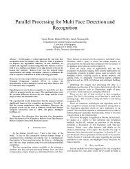
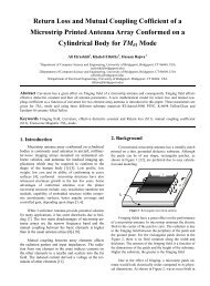
IEEE TRANSACTIONS ON CIRCUITS AND SYSTEMS, VOL. 31, NO. 5, MAY 1990 629Fig. 3. A <strong>modulo</strong> sum adder.111. THE PROPOSED MODULO ADDERCarry save adder (CSA) [13] has been proved to have highspeedin multioperand <strong>addition</strong>. Basically CSA depends on theidea of not completing the <strong>addition</strong> process at a certain stage,but postponing it to the final stage. In the intermediate stagesnumbers are represented as sum and carry to avoid the complete<strong>addition</strong> process.The idea of representing a number as a carry and a sum canbe used in the <strong>modulo</strong> <strong>addition</strong> to obtain a scheme that has aconstant speed which does not depend on the number of bits.The <strong>modulo</strong> adder is used to add two numbers A and B in<strong>modulo</strong> m. Fig. 3 shows that A is represented as a pair ofnumbers (A,,A,), B is also represented as (Bs,B,), and theoutput C is represented as (C,,C,). Each number is representedas a group of sum bits and carry bits. There is no uniquerepresentation <strong>for</strong> A, and A,. The condition that needs to besatisfied isIA, + ACIm = 14,.One possible representation isA, = JAl, A, = 0.The choice of a representation has no implication on the complexityof the design. With such representation, four numbers(A,, A,, B,, B,) need to be added, and two steps of CSA arerequired. After the <strong>addition</strong> process we need to detect if - Mor 2*(- M) is required to adjust the result. The adjustingprocess takes at most three steps. Since the adder has a fixednumber of steps-five-no matter how long A and B are, itcan be used in a multioperand pipelined <strong>addition</strong> scheme [141.3.1. The Modulo Addition AlgorithmThe proposed <strong>algorithm</strong> <strong>for</strong> <strong>modulo</strong> m <strong>addition</strong> of two numberscan be described as follows.Algorithm <strong>modulo</strong> add (A, B, Result)Znput: Two variables A and B in <strong>modulo</strong> m,A is representedas A, and A,. B is represented as B, and B,. Allvariables are n bit numbers (2"-' < m Q 2").Output: Variable Result represented as Result. and Result,.The relation between A, B, and Result is: Result =IA + BIm.Procedure:beginDo in parallelbeginCall Sum(temp,, A,, A,, B,)Call Carry(temp,, A,, A,, B,)endDo in parallelbeginCall Carry(temp,, temp,, temp,, B,)Call Carry(temp,, temp,, temp,, B,)endCase (temp, [n + 11 -temp, [n + 11) of0: Do in parallelbeginResult, := temp,Result, := temp,endexit1: do in parallelbeginCall Sum(temp,, temp,, temp,, rn))Call Carry(temp,, temp,, temp,, (2"- rn))end2: Do in parallelbeginCall sum(temp,, temp,, temp,, 2*(2" - rn))Call CarryItemp,, temp,, temp,, 2*(2" - rn))endend caseCase (temp, [n + 11) of0: do in parallelbeginResult, temp,Result ,:= temp,endexit1: Do in parallelbeginCall Sum(temp,, temp,, temp,, (2"- rn))Call Carry(temp,, temp,, temp,, (2"- rn))endend caseCase (temp, [n + 11) of0: do in parallelbeginResult, := temp,Result, := temp,end1: Do in parallelbeginCall Sum(temp,, temp,, temp,, (2"- m))Call Carry(temp,,, tempo,, temp,, (2" - m))endDo in parallelbeginResult, := temp,Result, := temp,,endend caseend.Sum(A,B,C,D)beginDo in parallel (1 < i Q n)~[i] :=(B[i]A C[i]) V (B[i] A D[i])V (C[i] A D[il)endCarry (A, B, C, 0)beginA[1] := 0Do in parallel (1 < i < n)A[ i + 11 := B[ i] CB C[i] CBD[ i]endAn implementation of the <strong>algorithm</strong> is shown in Fig. 4.Authorized licensed use limited to: University of Bridgeport. Downloaded on February 24,2010 at 11:38:37 EST from IEEE Xplore. Restrictions apply.
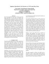
630 IEEE TRANSACTIONS ON CIRCUITS AND SYSTEMS, VOL. 31, NO. 5, MAY 19902'- M2( 2'-2'- M2( 2'- M )2n- M2( 2'- M 10 - JJ-J$&jF*..." .............."....................Initial: As= 101 1 1 11 101 1 1Ac. 11001 I I01 101Bp 11 1100010101Bp 1010101 1001 1M-2050 , N I 12Step 1. As= 101 11 11101 11Ac* 1100111011018.; 111100010101______-____---temp, = 10000000 I I 1 1temp,;llI! 11 1101010Step 2. temp,. 100000001 11 Itemp,: 11 11 11101010&. 10101011001 1______-___----temp,. l10101010110temp,=Ij010101010 1 10step 3. tamp,. 110101010110temp,. 0101010101102(2"- M) = 11 11 11 111100temp,= 01 I 1 11 11 1100temp6:ij101010101 100pia ....................................+-Ti!/0 Resultln] s Result[nl c#i!Fig. 4. Different stages of the <strong>modulo</strong> adder.ResultLl 1 Result[l ISCFig. 5.Step 4. temp,. 01 1 I I 1 11 1100temp6= 101010101 100____________--2"-n = 011111111110temp,= 1010101011 IOternpp.nl111t 1 111000Resu/fs= li?/i?/O/i?/ Ill)RPs/lIt0 : I / I I I I I I lC?i?C?A detailed example <strong>for</strong> the <strong>modulo</strong> <strong>addition</strong>Theorem 1: The <strong>modulo</strong> adder scheme <strong>for</strong> adding two n-bitnumbers in <strong>modulo</strong> rn has an asymptotic time complexity O(1).Proof: To prove that the number of steps is constant (five)we need to prove that the last carry is equal to zero in five orless steps. Induction is used to prove the correctness of thetheorem on the number of bits n.1) Basis step: <strong>for</strong> n=0, it means that we do not add anynumbers and in this case the required number of steps is zero.2) Induction hypothesis: assume <strong>for</strong> a fixed arbitrary n > 0that the maximum number of steps is five.3) Induction step: <strong>for</strong> numbers with n + 1 bits let:7 = temp, [ n + 11 +temp, [n +2].Then we have the following cases.(a) 7 = 0: then the carry propagation stopped at bit n, and itends after five steps at most according to the induction hypothesis.(b) 7 = 1: then the correction is 2"+' - rn in step 3. Sincern > 2", then 2"+' - rn < 2", which means that (2"+' - rn) [n]=0. The worst case we get to have temp,[ n + 11 and temp,[ n + 21to be equal to one. This means that temp,[n + 11 = 0 andtemp, [ n + 21 = 1, then temp, [ n + 21 = 0. In this case the correctionis done in two steps (step 3 and step 4).(c) 7 = 2: then the correction is 2*(2"+l- rn) in step 3. Theworst case we get to have temp, [ n + 11, temp, [ n + 21, and2*(2"+' - rn) to be equal to one. Then temp,[n + 11 = 1,temp6[n+1]=1, and 2"+'-M=0. At step 4 temp,[n+l]=Oand temp,[n +2]= 1. At step 5 temp,[n +1]= 1 and templ0[n+ 21 = 0. In this case the correction is done in three steps (steps3-5).As an example, the <strong>modulo</strong> <strong>addition</strong> of A = 1272 and B = 450<strong>for</strong> rn = 2050 is shown in Fig. 5. There is no unique representation<strong>for</strong> A and B. One valid representation is shown in thisfigure. The detailed <strong>modulo</strong> <strong>addition</strong> operation is shown in thisexample. In step 1 we get temp,[l3]= 1, and in step 2 we gettemp,[l3]= 1, which means that at step 3 we have to add2(2" - M). At step 3 we get temp6[13] = 1, which means that atstep 4 we have to add 2" - M. At step 4 we get temp,[l3] = 0,which means that the <strong>addition</strong> process stops at step 4. The resultof step 4 is the final result.IV. MODULO ADDER EVALUATIONUsing the VLSI model of computation <strong>for</strong> asymptotic complexity[15], a comparative study <strong>for</strong> the proposed adder isanalyzed. For adder I (Fig. 11, using the binary adder of Brentand Kung [16], the complexity measures will be as follows:A = O(log rn log log rn) = O( n log n)T=O(loglogrn) =O(logn)AT, = O( n(10g .I,).For adder I1 (Fig. 21, using the complexity analysis of thecorrelation table of [17]:A = O(Iogrn IogIogrn + rnlog rn) = O(nI0gn +2"n) = O(n2")T=O(loglogrn+ logrn) =O(logn+n)=O(n)AT, = qn32n).For the proposed adder,A = O(n)T = O(1)AT,= O(n).V. CONCLUSIONSThe <strong>modulo</strong> adder introduced in this paper has a total timedelaycomplexity of O(1) <strong>for</strong> adding two n-bit numbers in <strong>modulo</strong>rn. Based on the analysis of Section IV, this adder is theAuthorized licensed use limited to: University of Bridgeport. Downloaded on February 24,2010 at 11:38:37 EST from IEEE Xplore. Restrictions apply.
IEEE TRANSACTIONS ON CIRCUITS AND SYSTEMS, VOL. 37, NO. 5, MAY 1990 63 1fastest and the most area efficient <strong>for</strong> large moduli. The proposeddesign has the following advantages.1) It does not have any limitation on the size of the modulus.2) It is quite modular, and it is a two-dimensional array ofone type cell (full-adder).3) It is easy to pipeline.4) It is very efficient architecture <strong>for</strong> the implementation ofthe CRT decoding [14].REF ER EN c E sF. J. Taylor, “Residue arithmetic: A tutorial with examples,” IEEEComput. Mag., pp. 50-62, May 1984.M. A. Bayoumi, G. A. Jullien, and W. C. Miller, “A look-up tableVLSI design methodology <strong>for</strong> RNS structures used in DSP applications,”IEEE Trans. Circuits Syst., vol. CAS-34, pp. 604-616, June 1987.M. A. Bayoumi, “A high speed VLSI complex digital signal processorbased on quadratic residue number system,” in VLSI Signal ProcessingII. New York IEEE Press, 1986, pp. 200-211.-, “Digital filter VLSI systolic arrays over finite fields <strong>for</strong> DSPapplications,” in Proc. 6th IEEE Ann. Phoenix Conf. on Computers andCommunications, pp. 194-199, Feb. 1987.W. Jenkins and E. Davidson, “A custom-designed integrated circuit <strong>for</strong>the realization of residue number digital filters,” in Proc. ICASSP1985, pp. 220-223, Mar. 1985.N. S. Szabo and R. I. Tanaka, Residue Arithmatic and Its Applications toComputer Technology. New York McGraw-Hill, 1967.M. A. Soderstrand and E. L. Fields, “Multipliers and residue numberarithmetic digital filters,” Electron. Lett., vol. 13, no. 6, pp. 164-166,Mar. 1977.D. K. Banerji, “A novel implementation method <strong>for</strong> <strong>addition</strong> andsubtraction in residue number systems,” IEEE Trans. Comput., vol.C-23, pp. 106-109, Jan. 1974.M. A. Bayoumi, G. A. Jullien, and W. C. Miller, “A VLSI implementationof residue adders,” IEEE Trans. Circuits Syst., vol. CAS-34, pp.284-288, Mar. 1987.M. A. Bayoumi, “VLSI PLA structures <strong>for</strong> residue number systemsarithmetic implementations,” in Proc. ISCAS 1987, 1987.C. L. Chiang and L. Johnsson, “Residue arithmetic and VLSI,” inProc. ICCD 83, pp. 80-83, Oct. 1983.K. M. Elleithy, “On hit-parallel processing <strong>for</strong> <strong>modulo</strong> arithmetic,”VLSI Tech. Rep. TR86-8-1, Ctr. Advanced Computer Studies, Univ. ofSouthwestern Louisiana, 1986.K. Hwang, Computer Arithmetic: Principles, Architecture, and Design.New York: Wiley, 1978.K. M. Elleithy, “On the bit-parallel implementation <strong>for</strong> the Chineseremainder theorem,’’ VLSI Tech. Rep. TR87-8-1, Ctr. Advanced ComputerStudies, Univ. of Southwestern Louisiana, 1987.G. Alia and E. Materinelli, “A VLSI <strong>algorithm</strong> <strong>for</strong> direct and reverseconversion from weighted binary number system to residue numbersystem,” IEEE Trans. Circuits Syst., vol. CAS-31, pp. 1033-1039, 1984.R. P. Brent and H. T. Kung, “A regular layout <strong>for</strong> parallel adders,”IEEE Trans. Comput. vol. C-31, pp. 260-264, Mar. 1982.M. A. Bayoumi, “Lower bounds <strong>for</strong> VLSI implementation of residuenumber system architectures,” Integration, The VLSI J., vol. 4, no. 4, pp.263-269, Dec. 1986.Adjusting the Parameters in Elliptic-Function FiltersH. J. ORCHARDAbstract -When designing elliptic-function filters there is usuallysome margin in per<strong>for</strong>mance to be distributed over the defining parameters.A recent paper offered some comparatively complicated <strong>for</strong>mulas<strong>for</strong> use in this stage of the design. However, a simpler method, originallydue to Darlington, is available and is described briefly.I. INTRODUCTIONThe solution given by Vlcek and Unbehauen [l] to what theyrefer to as the “degree equation” <strong>for</strong> elliptic-function filters isexact, but rather complicated <strong>for</strong> the intended use in adjustingthe parameters at the beginning of a design, and involvescomputing several elliptic functions of rational fractions of aquarterperiod. High precision is unnecessary at this stage in thedesign, and a much simpler <strong>for</strong>mula which allows one to achievethe same end result with a pocket calculator was in fact given byDarlington [2] just 50 years ago, but seems to have been overlooked.The purpose of this note is to explain his <strong>for</strong>mula inmore detail than appeared in [2] and to expand on it slightly.In the design of an elliptic-function filter one is given aspecification <strong>for</strong>: The passband ripple, up, the minimum stopbandloss, a,, (both in decibels) and the elliptic modulus k =wp/os, where op is the passband-edge frequency and os is thestopband-edge frequency. From these one must first find thesmallest integral value of the degree n that can be used. Thischoice <strong>for</strong> n will normally cause the filter to be slightly betterthan is called <strong>for</strong> in the specification, so one can adjust thevalues of up, a, and k that one uses in the design to allow somemargin inside the specification. The relation between these fourparameters, up, a,, k and n is given by the “degree equation.”11. DEFINITION OF THE ELLIPTIC-FUNCTION FILTERThe power ratio <strong>for</strong> an elliptic-function filter is most convenientlydefined by a pair of equations involving a parametricvariable, exactly analogous to those <strong>for</strong> the well-known Chebyshevfilter. The latter is defined by10~’’~ =I+ e2cos2nun = COSU(la)(1b)where U is the parametric variable and n is the degree. Thepassband edge is normalized to = 1 and the passband ripple isup = 10 log (1 + E‘) dB.The equations <strong>for</strong> the elliptic-function filter are obtained byreplacing the cosines in (1) by the Jacobian cd elliptic functionsand take the <strong>for</strong>m’10n/’O = 1 + c2cd2(nuK, /K;k,)fl=cd(u;k)(3a)As in (l), this definition holds <strong>for</strong> both odd and even values ofthe degree n. K, and K are the real quarterperiods belongingto the elliptic functions with moduli k, and k in (3a) and (3b)respectively. The fre uency scale is still normalized to R = 1 atwp, rather than to & as in [l] and [2]; the latter normalization,though nicer <strong>for</strong> theoretical work, is a nuisance in practicaldesign. passband ripple is again given by (2).In order <strong>for</strong> (3) to define a rational function, the periodOf cd(nuKl iK; in the plane, must fit exactly ?Itimes into the period rectangle of cd(u; k), just as the periodstrip of cos nu fits n times into the period strip of cos U. ThisManuscript received April 28, 1989. This letter was recommended byAssociate Editor T. R. Viswanathan.The author is with the Electrical Engineering Department, University ofCali<strong>for</strong>nia Los Angeles, Los Angeles, Ca 90024.IEEE Log Number 8930187.‘The cd function is the same as the sn function by a real quarter period,just as the cosine is the same as the sine shifted by ~/2. Using the cdfunction rather than the sn function as in [2], allows one to describe both oddand even degree cases with one common <strong>for</strong>mula.OO98-4094/90/0500-oS31~$01 .OO 01990 IEEEAuthorized licensed use limited to: University of Bridgeport. Downloaded on February 24,2010 at 11:38:37 EST from IEEE Xplore. Restrictions apply.