- Page 1 and 2: For New Technology NetworkRcorporat
- Page 3 and 4: WarrantyNTN warrants, to the origin
- Page 5 and 6: TECHNICAL DATA CONTENTS1. Classific
- Page 7 and 8: Classification and Characteristics
- Page 9 and 10: Classification and Characteristics
- Page 11 and 12: Classification and Characteristics
- Page 13 and 14: Classification and Characteristics
- Page 15 and 16: Bearing SelectionSelect bearing’s
- Page 17 and 18: Bearing Selection2.3 Selection of b
- Page 19: Load Rating and Life3. Load Rating
- Page 22 and 23: Load Rating and LifeThe basic stati
- Page 24 and 25: Bearing Load CalculationTable 4.2 G
- Page 26 and 27: Bearing Load Calculation4.3 Mean lo
- Page 28 and 29: Bearing Load CalculationTable 4.5 B
- Page 30 and 31: Bearing Load Calculation(Example 4)
- Page 32 and 33: Boundary Dimensions and Bearing Num
- Page 34 and 35: Boundary Dimensions and Bearing Num
- Page 37 and 38: Bearing Tolerances6. Bearing Tolera
- Page 39 and 40: Bearing TolerancesMean bore diamete
- Page 41 and 42: Bearing TolerancesUnitmInner ringax
- Page 43 and 44: Bearing TolerancesTMaster cupsub-un
- Page 45 and 46: Bearing TolerancesInner ringaxial r
- Page 47 and 48: Bearing TolerancesTable 6.8 Toleran
- Page 49 and 50: Bearing Tolerances!d!d2ddd+!dd+!dBT
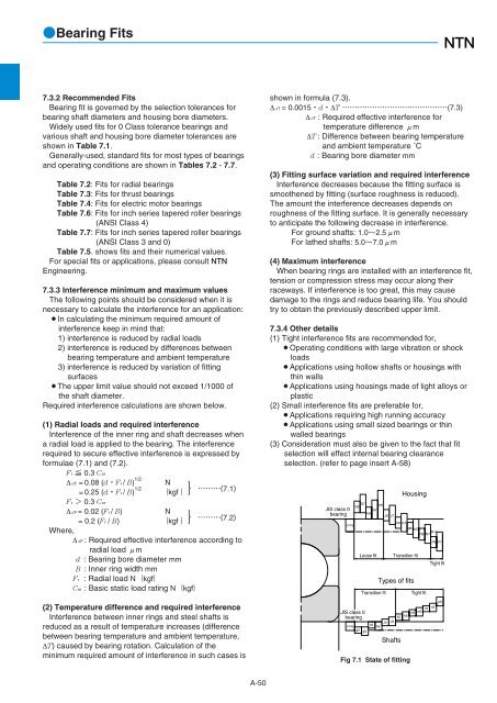
- Page 51: Bearing Fits7. Bearing Fits7.1 Fitt
- Page 55 and 56: Bearing FitsTable 7.3 Standard fits
- Page 57 and 58: Bearing FitsA-5512T12.5T13.5T16.5T2
- Page 59 and 60: Bearing FitsTable 7.7 General fitti
- Page 61 and 62: Bearing Internal Clearance and Prel
- Page 63 and 64: Nominal bore diameterdmm10241024303
- Page 65 and 66: Bearing Internal Clearance and Prel
- Page 67 and 68: Bearing Internal Clearance and Prel
- Page 69 and 70: Bearing Internal Clearance and Prel
- Page 71 and 72: Bearing Internal Clearance and Prel
- Page 73 and 74: Friction and Temperature Rise10. Fr
- Page 75 and 76: Lubricationviscosity base oil are b
- Page 77 and 78: LubricationAluminum greaseAI soapNo
- Page 79 and 80: Lubrication11.5 Oil lubricationOil
- Page 81 and 82: LubricationTable 11.9 Factor KExpel
- Page 83 and 84: External bearing sealing devicesTyp
- Page 85 and 86: Bearing Materials13. Bearing Materi
- Page 87 and 88: Shaft and Housing Design14. Shaft a
- Page 89 and 90: Shaft and Housing Design14.2.3 Thru
- Page 91 and 92: Bearing Handling280280Diametric exp
- Page 93 and 94: Bearing HandlingTable 15.1 Installa
- Page 95 and 96: Bearing HandlingLarge bearings, ins
- Page 97 and 98: A-95
- Page 99 and 100: Bearing Damage and Corrective Measu
- Page 101 and 102: Bearing Damage and Corrective Measu
- Page 103 and 104:
Technical DataThis data is based on
- Page 105 and 106:
Technical Data17.5 Fitting surface
- Page 107 and 108:
Ball and Roller Bearings
- Page 109:
Tapered Roller Bearings !!!!!!!!!!!
- Page 112 and 113:
!Deep Groove Ball Bearings2. Standa
- Page 114 and 115:
Deep Groove Ball BearingsBrrDdd Op
- Page 116 and 117:
Deep Groove Ball BearingsBrrDdd Op
- Page 118 and 119:
Deep Groove Ball Bearingsd Boundar
- Page 120 and 121:
Deep Groove Ball BearingsBrrDdd Op
- Page 122 and 123:
Deep Groove Ball BearingsBrrDdd Op
- Page 124 and 125:
Deep Groove Ball BearingsBrrDdd Op
- Page 126 and 127:
Deep Groove Ball BearingsBrrarraDdD
- Page 128 and 129:
Deep Groove Ball BearingsBrrarraDdD
- Page 130 and 131:
Deep Groove Ball BearingsBrrarraDdD
- Page 132 and 133:
Expansion Compensating BearingsBrrD
- Page 134 and 135:
AC BearingsBrrDdd Open typeShielde
- Page 137 and 138:
!Miniature and Extra Small Bearings
- Page 139 and 140:
!Miniature and Extra Small Bearings
- Page 141 and 142:
Miniature and Extra Small Ball Bear
- Page 143 and 144:
Miniature and Extra Small Ball Bear
- Page 145 and 146:
Miniature and Extra Small Ball Bear
- Page 147:
Miniature and Extra Small Ball Bear
- Page 150 and 151:
Angular Contact Ball Bearings1.2 Fo
- Page 152 and 153:
Single and Duplex Angular Contact B
- Page 154 and 155:
Single and Duplex Angular Contact B
- Page 156 and 157:
Single and Duplex Angular Contact B
- Page 158 and 159:
Single and Duplex Angular Contact B
- Page 160 and 161:
Single and Duplex Angular Contact B
- Page 162 and 163:
Single and Duplex Angular Contact B
- Page 164 and 165:
Four-Point Contact Ball BearingsQJ
- Page 166 and 167:
Double Row Angular Contact Ball Bea
- Page 168 and 169:
Double Row Angular Contact Ball Bea
- Page 171 and 172:
Self-Aligning Ball Bearings1. Desig
- Page 173 and 174:
Self-Aligning Ball BearingsEquivale
- Page 175 and 176:
Self-Aligning Ball BearingsEquivale
- Page 177 and 178:
Self-Aligning Ball BearingsEquivale
- Page 179 and 180:
Adapters(for self-aligning ball bea
- Page 181:
AdaptersB-75
- Page 184 and 185:
Cylindrical Roller BearingsTable 2
- Page 186 and 187:
Cylindrical Roller BearingsBBrr1rr1
- Page 188 and 189:
Cylindrical Roller BearingsBBrr1rr1
- Page 190 and 191:
Cylindrical Roller BearingsBBrr1rr1
- Page 192 and 193:
Cylindrical Roller BearingsBBrr1rr1
- Page 194 and 195:
Cylindrical Roller BearingsBBrr1rr1
- Page 196 and 197:
Cylindrical Roller BearingsBBrr1rr1
- Page 198 and 199:
Cylindrical Roller BearingsBBrr1rr1
- Page 200 and 201:
Cylindrical Roller BearingsBBrr1rr1
- Page 202 and 203:
Cylindrical Roller BearingsBBrr1rr1
- Page 204 and 205:
L Type Loose RibL type collar ringB
- Page 206 and 207:
L Type Loose RibL type collar ringB
- Page 208 and 209:
Double Row Cylindrical Roller Beari
- Page 210 and 211:
Double Row Cylindrical Roller Beari
- Page 212 and 213:
Double Row Cylindrical Roller Beari
- Page 214 and 215:
Four-Row Cylindrical Roller Bearing
- Page 216 and 217:
Four-Row Cylindrical Roller Bearing
- Page 218 and 219:
Four-Row Cylindrical Roller Bearing
- Page 220 and 221:
Four-Row Cylindrical Roller Bearing
- Page 222 and 223:
Four-Row Cylindrical Roller Bearing
- Page 225 and 226:
Tapered Roller BearingsSingle row t
- Page 227 and 228:
Tapered Roller Bearings5. ECO-Top t
- Page 229 and 230:
Tapered Roller BearingsInch series
- Page 231 and 232:
Tapered Roller BearingsInch series
- Page 233 and 234:
Tapered Roller BearingsInch series
- Page 235 and 236:
Tapered Roller BearingsSaSbr1aEquiv
- Page 237 and 238:
Tapered Roller BearingsSaSbr1aEquiv
- Page 239 and 240:
Tapered Roller BearingsSaSbr1aEquiv
- Page 241 and 242:
Tapered Roller BearingsSaSbr1aEquiv
- Page 243 and 244:
Tapered Roller BearingsSaSbr1aEquiv
- Page 245 and 246:
Tapered Roller BearingsSaSbr1aEquiv
- Page 247 and 248:
Tapered Roller BearingsSaSbr1aEquiv
- Page 249 and 250:
Tapered Roller BearingsSaSbr1aEquiv
- Page 251 and 252:
Tapered Roller BearingsSaSbr1aEquiv
- Page 253 and 254:
Tapered Roller BearingsDa dbr1arada
- Page 255 and 256:
Tapered Roller BearingsDa dbr1arada
- Page 257 and 258:
Tapered Roller Bearingsr1araEquival
- Page 259 and 260:
Tapered Roller Bearingsr1araEquival
- Page 261 and 262:
Tapered Roller Bearingsr1araEquival
- Page 263 and 264:
Tapered Roller Bearingsr1araEquival
- Page 265 and 266:
Tapered Roller Bearingsr1araEquival
- Page 267 and 268:
Tapered Roller Bearingsr1araEquival
- Page 269 and 270:
Tapered Roller BearingsDa dbr1arada
- Page 271 and 272:
Tapered Roller BearingsDa dbr1arada
- Page 273 and 274:
Tapered Roller BearingsDa dbr1arada
- Page 275 and 276:
Tapered Roller BearingsDa dbr1arada
- Page 277 and 278:
Tapered Roller BearingsDa dbr1arada
- Page 279 and 280:
Tapered Roller BearingsDa dbr1arada
- Page 281 and 282:
Tapered Roller BearingsDa dbr1arada
- Page 283 and 284:
Tapered Roller BearingsDa dbr1arada
- Page 285 and 286:
Tapered Roller BearingsDa dbr1arada
- Page 287 and 288:
Tapered Roller BearingsDa dbr1arada
- Page 289 and 290:
Tapered Roller BearingsDa dbr1arada
- Page 291 and 292:
Double Row Tapered Roller BearingsS
- Page 293 and 294:
Double Row Tapered Roller BearingsS
- Page 295 and 296:
Double Row Tapered Roller BearingsS
- Page 297 and 298:
Double Row Tapered Roller BearingsS
- Page 299 and 300:
Double Row Tapered Roller BearingsS
- Page 301 and 302:
Double Row Tapered Roller BearingsS
- Page 303 and 304:
Double Row Tapered Roller BearingsS
- Page 305 and 306:
Double Row Tapered Roller BearingsS
- Page 307 and 308:
Double Row Tapered Roller BearingsS
- Page 309 and 310:
Four Row Tapered Roller BearingsBea
- Page 311 and 312:
Four Row Tapered Roller BearingsBea
- Page 313 and 314:
Four Row Tapered Roller BearingsBea
- Page 315 and 316:
Four Row Tapered Roller BearingsBea
- Page 317 and 318:
Four Row Tapered Roller BearingsBea
- Page 319 and 320:
Four Row Tapered Roller BearingsBea
- Page 321 and 322:
Four Row Tapered Roller BearingsBea
- Page 323:
Four Row Tapered Roller BearingsBea
- Page 326 and 327:
Spherical Roller Bearings2. Standar
- Page 328 and 329:
Spherical Roller BearingsBrrDddCyli
- Page 330 and 331:
Spherical Roller BearingsBrrDddCyli
- Page 332 and 333:
Spherical Roller BearingsBrrDddCyli
- Page 334 and 335:
Spherical Roller BearingsBrrDddCyli
- Page 336 and 337:
Spherical Roller BearingsBrrDddCyli
- Page 338 and 339:
Spherical Roller BearingsBrrDddCyli
- Page 340 and 341:
Spherical Roller BearingsBrrDddCyli
- Page 342 and 343:
Spherical Roller BearingsBrrDddCyli
- Page 344 and 345:
Spherical Roller BearingsBrrDddCyli
- Page 346 and 347:
Spherical Roller BearingsBrrDddCyli
- Page 348 and 349:
Adapter(For spherical roller bearin
- Page 350 and 351:
Adapter(For spherical roller bearin
- Page 352 and 353:
Adapter(For spherical roller bearin
- Page 354 and 355:
Withdrawal Sleeves(For spherical ro
- Page 356 and 357:
Withdrawal Sleeves(For spherical ro
- Page 358 and 359:
Withdrawal Sleeves(For spherical ro
- Page 361 and 362:
Thrust BearingsSingle direction thr
- Page 363 and 364:
Thrust BearingsB-257
- Page 365 and 366:
Single Direction Thrust Ball Bearin
- Page 367 and 368:
Single Direction Thrust Ball Bearin
- Page 369 and 370:
Spherical Roller Thrust Bearingsdar
- Page 371 and 372:
Spherical Roller Thrust Bearingsdar
- Page 373 and 374:
Spherical Roller Thrust Bearingsdar
- Page 375 and 376:
Locknuts, Lockwashers& Lockplates
- Page 377 and 378:
LocknutsReferencewithdrawal sleeve
- Page 379 and 380:
LocknutsReferencebore no. lock- Sh
- Page 381 and 382:
Locknutsr1gbhsrB30˚ Gd2dPd6d1Beari
- Page 383 and 384:
NutsReferencewithdrawal sleeve no.A
- Page 386 and 387:
LockwashersSeries AWƒ25˚r2B2ƒ1B1
- Page 388 and 389:
LockwashersSeries AWLƒ25˚r2B2ƒ1B
- Page 390 and 391:
Snap rings and grooves for rolling
- Page 392 and 393:
Snap rings and grooves for rolling
- Page 394 and 395:
Catalog List and Appendix Table Con
- Page 396 and 397:
Catalog ListCATALOG TITLESCATALOG N
- Page 398 and 399:
D-41234567890001020304/2205/2806/32
- Page 400 and 401:
Appendix TableAppendix table 2: Com
- Page 402 and 403:
Appendix TableAppendix table 5: Dim
- Page 404 and 405:
Appendix TableAppendix table 6: Dim
- Page 406 and 407:
Appendix TableAppendix table 7: Bas
- Page 408 and 409:
Appendix TableAppendix table 9: Kgf
- Page 410 and 411:
D-16Rockwell hardnessBrinell hardne