First- and second-order piezoelectricity in III-V semiconductors
First- and second-order piezoelectricity in III-V semiconductors
First- and second-order piezoelectricity in III-V semiconductors

You also want an ePaper? Increase the reach of your titles
YUMPU automatically turns print PDFs into web optimized ePapers that Google loves.
PHYSICAL REVIEW B 84, 195207 (2011)<strong>First</strong>- <strong>and</strong> <strong>second</strong>-<strong>order</strong> <strong>piezoelectricity</strong> <strong>in</strong> <strong>III</strong>-V <strong>semiconductors</strong>Annie Beya-Wakata, Pierre-Yves Prodhomme, <strong>and</strong> Gabriel Bester *Max-Planck-Institut für Festkörperforschung, Heisenbergstrasse 1, DE-70569 Stuttgart, Germany(Received 6 June 2011; revised manuscript received 3 November 2011; published 28 November 2011)We present the results of first-pr<strong>in</strong>ciples plane-wave pseudopotential calculations of piezoelectric coefficientsof first <strong>and</strong> <strong>second</strong> <strong>order</strong> for a total of n<strong>in</strong>e <strong>III</strong>-V b<strong>in</strong>ary phases (AlP, AlAs, AlSb, GaP, GaAs, GaSb, InP,InAs, InSb) of z<strong>in</strong>c-blende <strong>semiconductors</strong>. These coefficients are used to calculate the piezoelectric fields for[111]-oriented quantum wells (QWs) with different well-barrier comb<strong>in</strong>ations <strong>and</strong> various dimensions. We derivean approximate analytic expression for the stra<strong>in</strong> tensor <strong>in</strong> the case of pseudomorphic growth along an arbitrarygrowth direction. Together with the piezoelectric coefficients, this allows a simple calculation of the piezoelectricfield up to <strong>second</strong> <strong>order</strong> <strong>in</strong> stra<strong>in</strong> for an arbitrary growth direction <strong>and</strong> any material comb<strong>in</strong>ation with<strong>in</strong> the n<strong>in</strong>e<strong>III</strong>-Vs presented here. Nonl<strong>in</strong>ear contributions to the polarization are shown to be of significant magnitude forall the materials presented. In some cases the field is <strong>in</strong>creased by the <strong>second</strong>-<strong>order</strong> terms; <strong>in</strong> some cases it isdecreased. We analyze the chemical trends of the obta<strong>in</strong>ed coefficients. We compare our results to availableexperiments <strong>and</strong> f<strong>in</strong>d good agreement <strong>in</strong> one-third of the cases, while for the rema<strong>in</strong><strong>in</strong>g cases the calculated fieldis larger to significantly larger than <strong>in</strong> the measurements. We discuss the popular experimental techniques <strong>and</strong>highlight possible reasons for the discrepancies.DOI: 10.1103/PhysRevB.84.195207PACS number(s): 77.65.Bn, 73.21.Fg, 77.65.LyI. INTRODUCTIONHeterostructures, made of materials with different latticeconstants, are subjected to elastic deformations. In the presenceof a shear stra<strong>in</strong>, piezoelectric fields develop <strong>in</strong> crystals withz<strong>in</strong>c-blende structure. The existence of <strong>in</strong>ternal piezoelectricfields (sign, magnitude, as well as their consequences) with<strong>in</strong>[111]-grown stra<strong>in</strong>ed semiconductor layers was establishedtheoretically <strong>in</strong> a series of papers by Mailhiot <strong>and</strong> Smith. 1–7In fact, the [111] orientation offers the possibility to producepiezoelectric fields, which can easily exceed 100 kV/cm. S<strong>in</strong>cethen, a great deal of theoretical <strong>and</strong> experimental research hasbeen devoted to the underst<strong>and</strong><strong>in</strong>g of the piezoelectric propertiesof bulk (e.g., Refs. 8 <strong>and</strong> 9), quantum wells (QWs) (e.g.,Refs. 10–12), quantum wires (e.g., Refs. 13–15), <strong>and</strong> quantumdots (e.g., Refs. 16–20). The work on QWs has been especiallydecisive s<strong>in</strong>ce the screen<strong>in</strong>g of the piezoelectric fields can bestrongly reduced under most experimental conditions. Conclusionsdrawn from bulk measurements, on the other h<strong>and</strong>, areusually shadowed by the appearance of free carriers (residual,<strong>in</strong>tr<strong>in</strong>sic, or photo<strong>in</strong>duced) effectively screen<strong>in</strong>g the field. Inthe case of <strong>III</strong>-V z<strong>in</strong>c-blende heterostructures specifically,the <strong>in</strong>tr<strong>in</strong>sic stra<strong>in</strong>-<strong>in</strong>duced electric fields are held responsiblefor strong effects on the transport properties, 21 opticalcharacteristics, 22–24 <strong>and</strong> acousto-optical modulation 25 <strong>in</strong> a waywhich may lead to the microstructural eng<strong>in</strong>eer<strong>in</strong>g of noveloptical <strong>and</strong> electronic devices. 26,27 The <strong>in</strong>terest on these modifiedproperties is therefore manyfold: the underst<strong>and</strong><strong>in</strong>g of thephysics <strong>in</strong>volved <strong>and</strong> the development of new applications, thatis, <strong>in</strong>tegrated, mixed-effect devices, optical switches, modulators,<strong>and</strong> nonl<strong>in</strong>ear devices. 28–32 A recent paper by Lew YanVoon 33 reviews recent work <strong>in</strong>volv<strong>in</strong>g piezoelectric effects.The existence of a nonl<strong>in</strong>ear piezoelectric effect, subjectto this work, was first mentioned by Cibert et al. 34,35 forII-VI CdTe QWs. They argued that this material was an idealc<strong>and</strong>idate for nonl<strong>in</strong>ear piezoelectric effects due to its smallpiezoelectric coefficient. They measured a piezoelectric fieldthat depended <strong>in</strong> a nonl<strong>in</strong>ear fashion on the elastic stra<strong>in</strong>.Subsequent theoretical calculations 36 showed that the piezoelectrictensor <strong>in</strong> CdTe strongly depends on the hydrostaticpressure, but very little on the traceless stra<strong>in</strong>. The authorconcluded that for CdTe, where the l<strong>in</strong>ear coefficient is verysmall, its hydrostatic stra<strong>in</strong> dependence should be taken <strong>in</strong>toaccount. They further speculated that the nonl<strong>in</strong>ear termsshould give a small contribution <strong>in</strong> materials such as GaAs,due to a large l<strong>in</strong>ear piezoelectric effect. The methodology forthe calculation of <strong>second</strong>-<strong>order</strong> <strong>piezoelectricity</strong> with<strong>in</strong> densityfunctional theory was developed by Bester et al. 37 <strong>and</strong> appliedto the <strong>III</strong>-V InAs/GaAs QWs. 37 The effect of the <strong>second</strong>-<strong>order</strong>terms for In x Ga 1-x As/GaAs [111] QWs with conventionalcompositions (x 0.20) was shown to reduce the field byaround 20%. In the case of the popular In x Ga 1-x As quantumdots embedded <strong>in</strong> GaAs, the <strong>second</strong>-<strong>order</strong> effect was shownto nearly cancel the first-<strong>order</strong> effect. 38 The <strong>in</strong>vestigationon the balance between l<strong>in</strong>ear <strong>and</strong> quadratic piezoelectricterms was then extended to QDs of different shapes <strong>and</strong>compositions. 13,18,19,39,40 The effect of <strong>second</strong>-<strong>order</strong> <strong>piezoelectricity</strong>on the pressure coefficient of the light emission wasfurther <strong>in</strong>vestigated <strong>in</strong> InGaAs/GaAs QWs. 41 The calculationsrevealed that changes of the built-<strong>in</strong> electric field with pressure<strong>in</strong> (111)-oriented QWs are significantly enlarged by the effectof nonl<strong>in</strong>ear <strong>piezoelectricity</strong>, <strong>in</strong> comparison to the case whenl<strong>in</strong>ear <strong>piezoelectricity</strong> is used. 41In this paper we calculate via first-pr<strong>in</strong>ciples plane-wavepseudopotentials calculations the l<strong>in</strong>ear <strong>and</strong> quadratic piezoelectriccoefficients for a total of n<strong>in</strong>e <strong>III</strong>-V b<strong>in</strong>ary compounds([Al,Ga,In]-[P,As,Sb]) with z<strong>in</strong>c-blende structure. Us<strong>in</strong>g thesecoefficients we calculate the piezoelectric fields for 14 differentQWs. We f<strong>in</strong>d large nonl<strong>in</strong>ear contributions for all the <strong>in</strong>vestigatedmaterials. The paper is organized as follows. In Sec. II wereview the methodology <strong>and</strong> outl<strong>in</strong>e the computational details.We present our results <strong>and</strong> discuss trends we can identify <strong>in</strong> theobta<strong>in</strong>ed coefficients. Section <strong>III</strong> presents the methods used forthe calculation of the piezoelectric fields from the piezoelectriccoefficients. <strong>First</strong>, some considerations from electrostatics are1098-0121/2011/84(19)/195207(15) 195207-1©2011 American Physical Society
BEYA-WAKATA, PRODHOMME, AND BESTER PHYSICAL REVIEW B 84, 195207 (2011)presented. Then, the special case of a [111] QW is illustrated,as is the procedure to obta<strong>in</strong> the polarizations <strong>and</strong> fields forarbitrary crystallographic directions. Section IV describes theelectric fields we obta<strong>in</strong>ed for 14 different QWs grown alongthe [111] direction. Section V focuses on the InGaAs/GaAsmaterial system but shows results for arbitrary crystallographicgrowth direction. In Sec. VI we discuss the experimentaltechniques used to extract piezoelectric fields <strong>and</strong> <strong>in</strong> Sec. VIIwe compare our results to experiment. In Sec. V<strong>III</strong> we po<strong>in</strong>tout the importance of QW <strong>and</strong> barrier thicknesses, as well asQW composition.II. CALCULATION OF PIEZOELECTRIC COEFFICIENTSUP TO SECOND ORDER IN STRAINA. MethodologyPiezoelectricity is def<strong>in</strong>ed as the generation of electricpolarization by application of stress to a crystal lack<strong>in</strong>g acenter of <strong>in</strong>version. The electric polarization P μ as a functionof mechanical stra<strong>in</strong> η αβ can be written assum<strong>in</strong>g summationover repeat<strong>in</strong>g <strong>in</strong>dex <strong>and</strong> reta<strong>in</strong><strong>in</strong>g the <strong>second</strong> <strong>order</strong> <strong>in</strong> stra<strong>in</strong> asP μ = ∑ e μαβ η αβ + 1 ∑B μαβγ λ η αβ η γλ , (1)2αβαβγ λwhere e μαβ is the third-rank proper piezoelectric tensor ofthe unstra<strong>in</strong>ed material, while B μαβγ λ is a fifth-rank tensordef<strong>in</strong>ed below. The Greek <strong>in</strong>dexes μ, α, β, γ , <strong>and</strong> λ st<strong>and</strong> forthe x, y, <strong>and</strong> z axes of the Cartesian coord<strong>in</strong>ate system. Thesix <strong>in</strong>dependent components of the stra<strong>in</strong> tensor are given <strong>in</strong>the Voigt notation asη 1 = η xx , η 2 = η yy , η 3 = η zz ,η 4 = 2η yz , η 5 = 2η xz , η 6 = 2η xy .We use Lat<strong>in</strong> letters (i,j,k,...) for the Voigt <strong>in</strong>dex. Note thatsome authors, for example, Grimmer, 42 do not use the factorof 1/2<strong>in</strong>Eq.(1), which simply results <strong>in</strong> a different def<strong>in</strong>itionof B. The polarization component can then be written as6∑P μ = e μj η j + 1 6∑B μj k η j η k , (2)2j=1jk=1where B μj k represents the first-<strong>order</strong> change of thepiezoelectric tensor with stra<strong>in</strong>. Follow<strong>in</strong>g this def<strong>in</strong>ition, thepiezoelectric tensor can be def<strong>in</strong>ed as a function of stra<strong>in</strong>ẽ μj (η) = dP μ= e μj + ∑ B μj k η k . (3)dη jkThe tensor B μαβγ λ is symmetric under an <strong>in</strong>terchange of αβ<strong>and</strong> γλ.ItfollowsthatB μj k is symmetric under an <strong>in</strong>terchangeof j <strong>and</strong> k. The form of the fifth-rank piezoelectric tensorfor the 21 noncentrosymmetric crystallographic po<strong>in</strong>t groupswas first determ<strong>in</strong>ed by Koptsik <strong>and</strong> later by Nelson <strong>in</strong> aparticular orientation. 43,44 Recently, Grimmer 42 derived theform of the <strong>second</strong>-<strong>order</strong> piezoelectric tensor for crystals <strong>and</strong>quasicrystals of any symmetry <strong>and</strong> for all the orientations.The orientation of the symmetry elements for the z<strong>in</strong>c-blendecrystal structure [T d , F (¯43m)] show that there are threenonzero coefficients for e μj <strong>and</strong> that there is only one<strong>in</strong>dependent element to be determ<strong>in</strong>ed: e 14 = e 25 = e 36 .Thesymmetry restrictions on the B μj k tensor lead to 24 nonzerocoefficients with only three <strong>in</strong>dependent ones:B 114 = B 225 = B 336 ,B 124 = B 235 = B 316 = B 134 = B 215 = B 326 ,B 156 = B 345 = B 246 .The relations for the l<strong>in</strong>ear <strong>and</strong> quadratic dependence of the polarizationon the stra<strong>in</strong> tensor are given by P = P l + P nl , with⎛ ⎞η 4P l = e 14⎝η 5⎠ ,η 6⎛ ⎞ ⎛ ⎞ ⎛ ⎞η 1 η 4 η 4 (η 2 + η 3 ) η 5 η 6P nl = B 114⎝η 2 η 5⎠ + B 124⎝η 5 (η 3 + η 1 ) ⎠ + B 156⎝η 4 η 6⎠ .η 3 η 6 η 6 (η 1 + η 2 ) η 4 η 5(4)Our calculations of these tensor elements rely on thedensity functional perturbation theory (DFPT) techniquesapplied <strong>in</strong> the local density approximation (LDA) <strong>and</strong> thegeneralized gradient approximation (GGA) for the exchangecorrelation functional. The results reported here were obta<strong>in</strong>edfrom an implementation of the LDA <strong>in</strong> the framework of theABINIT code package. 45 The calculations were carried outus<strong>in</strong>g the Troullier-Mart<strong>in</strong>s (TM) pseudopotentials, 46 preparedby the Fritz Haber Institute code. 47 Some calculations werealso done us<strong>in</strong>g the relativistic separable pseudopotentials <strong>in</strong>the form of Hartwigsen, Goedecker, <strong>and</strong> Hutter (HGH). 48 Thenumerical results presented were computed by treat<strong>in</strong>g theelectrons of the 3d (Ga) <strong>and</strong> 4d (In) level as valence states.Plane waves up to 100 Ha were used to exp<strong>and</strong> the electronicstates <strong>and</strong> the Brillou<strong>in</strong> zone was sampled with a mesh of12 × 12 × 12 k po<strong>in</strong>ts.In <strong>order</strong> to obta<strong>in</strong> the coefficients e μj <strong>and</strong> B μj k weproceeded <strong>in</strong> the follow<strong>in</strong>g manner. <strong>First</strong>, we relaxed thelattice parameters for the b<strong>in</strong>ary compounds [Al, Ga, In]-[P,As, Sb]. Next, l<strong>in</strong>ear-response calculations of the l<strong>in</strong>ear bulkpiezoelectric constant e μj were carried out on these relaxedstructures us<strong>in</strong>g the DFPT module of the ABINIT package, 49,50which implements a direct calculation of the stra<strong>in</strong> derivativesof the quantities of <strong>in</strong>terest (Kohn-Sham wavefunctions,polarizations, etc.) via a cha<strong>in</strong> rule. Then, a f<strong>in</strong>ite-differencetechnique was used <strong>in</strong> <strong>order</strong> to obta<strong>in</strong> the “improper” (see nextsection) nonl<strong>in</strong>ear bulk piezoelectric tensors Bμj i k. With thestra<strong>in</strong> η i frozen at a particular value δ, the ions were allowed torelax, after which the piezoelectric tensor elements ẽ μj (δ)werecomputed us<strong>in</strong>g l<strong>in</strong>ear-response techniques. This is repeatedfor several values of δ up to 2% for the diagonal elements <strong>and</strong>up to 0.2% for the nondiagonal elements, then the dependenceof these elements on δ is fitted, <strong>and</strong> the l<strong>in</strong>ear dependenceextracted. This was done for different stra<strong>in</strong>s η i lead<strong>in</strong>g, <strong>in</strong> afirst step, to different improper <strong>second</strong>-<strong>order</strong> coefficients Bμj i k .B. From improper to proper <strong>second</strong>-<strong>order</strong> coefficientsUntil now, except for the last paragraph, we implicitlytalked about the “proper” coefficients. It has already beenshown that the proper (l<strong>in</strong>ear) piezoelectric coefficient e p does195207-2
FIRST- AND SECOND-ORDER PIEZOELECTRICITY IN ... PHYSICAL REVIEW B 84, 195207 (2011)not depend on the branch of the polarization as the improperpiezoelectric coefficient e i does. 51 We emphasize here that anaive computation of the <strong>second</strong>-<strong>order</strong> coefficient leads to animproper coefficient <strong>and</strong> that it needs to be corrected <strong>in</strong> <strong>order</strong> toget the proper <strong>second</strong>-<strong>order</strong> coefficient. The proper coefficientsshould be directly comparable to the experimental one; that is,they should not depend on the branch of polarization.In <strong>order</strong> to derive the proper <strong>second</strong>-<strong>order</strong> piezoelectrictensor we use Cartesian coord<strong>in</strong>ates, <strong>in</strong>stead of the Voigt <strong>in</strong>dex:Bμαβγ i λ = dẽp μαβ. (5)dη γλAccord<strong>in</strong>g to V<strong>and</strong>erbilt, 51 the proper piezoelectric tensor isgiven byẽ p μαβ =− 1 q ∑ dφ νR νμ , (6)2π dην αβwith φ ν the total Berry phase <strong>in</strong> direction ν, the volumeof the unit cell, <strong>and</strong> q the electronic charge. So the improper<strong>second</strong>-<strong>order</strong> piezo coefficient is given byB i μαβγ λ = 12πq 2d ∑dη γλνdφ νR νμ − 1 qdη αβ 2π ∑νdφ νdη αβdR νμdη γλ− 1 q ∑ d 2 φ νR νμ . (7)2π dɛν αβ dɛ γλThen one has to remember the def<strong>in</strong>ition of a stra<strong>in</strong>ed vector<strong>and</strong> a stra<strong>in</strong>ed volume,R να = R 0 να + ∑ η ντ R 0 τα , (8)τ<strong>and</strong> = 0 + ∑ η ττ 0 . (9)τS<strong>in</strong>ce by def<strong>in</strong>ition the stra<strong>in</strong> is symmetric (otherwise it is astra<strong>in</strong> + rotation), the follow<strong>in</strong>g property has to be ensured:η ντ = η τν = 1 2 (η ντ + η τν ). (10)This is an important po<strong>in</strong>t s<strong>in</strong>ce otherwise the B’s can lacksymmetry. Apply<strong>in</strong>g this property to the derivatives of the realspace lattice vectors <strong>and</strong> <strong>in</strong> the volume derivatives one f<strong>in</strong>dsdR να= 1 ∑(δ νγ δ τλ + δ νλ δ τγ )R 0 ταη γλ 2, (11)τ<strong>and</strong>d= ∑ δ τγ δ τλ 0 . (12)dη γλτThus, one f<strong>in</strong>ds (remember<strong>in</strong>g that the piezoelectric coefficientsare calculated at zero stra<strong>in</strong>, that is, R = R 0 <strong>and</strong> = 0 ),Bμαβγ i λ = 1 q2π δ ∑ dφ νγλ R νμ − 1 q ∑ dφ νdην αβ 2π dην αβ× 1 2 (δ μγ R νλ + δ μλ R νγ )− 1 q ∑ d 2 φ νR νμ . (13)2π dην αβ dη γλThe last term is what we call the proper <strong>second</strong>-<strong>order</strong>piezoelectric coefficient B p μαβγ λ .Rearrang<strong>in</strong>g the terms, one f<strong>in</strong>ally getsB p μαβγ λ = Bi μαβγ λ + δ γλe μαβ − 1 2 (δ μγ e λαγ + δ μλ e γαβ ). (14)Explicitly, the <strong>second</strong>-<strong>order</strong> piezoelectric coefficients calculated<strong>in</strong> this work are [when the B’s have three (five) <strong>in</strong>dicesit represents the Voigt (Cartesian) notation]B p 114 = Bp 11123 = Bi 11123 + δ 23e 111 − 1 2 (δ 12e 311 + δ 13 e 211 ),B p 114 = Bi 114 ,B p 141 = Bp 12311 = Bi 12311 + δ 11e 123 − 1 2 (δ 11e 123 + δ 11 e 123 ),B p 141 = Bi 141 ,B p 124 = Bp 12223 = Bi 12223 + δ 23e 122 − 1 2 (δ 12e 222 + δ 13 e 222 ),B p 124 = Bi 124 ,B p 142 = Bp 12322 = Bi 12322 + δ 22e 123 − 1 2 (δ 12e 223 + δ 12 e 223 ),B p 142 = Bi 142 + e 14,B p 156 = Bp 11312 = Bi 11312 + δ 12e 113 − 1 2 (δ 11e 213 + δ 12 e 113 ),B p 156 = Bi 156 − 1 2 e 25,B p 165 = Bp 11213 = Bi 11213 + δ 13e 112 − 1 2 (δ 11e 312 + δ 13 e 112 ),B p 165 = Bi 165 − 1 2 e 36.To illustrate quantitatively this correction, we take the coefficientsB 124 <strong>and</strong> B 142 of GaAs. The straightforward calculationdescribed <strong>in</strong> Sec. II A leads to the improper coefficients,−3.78 C/m 2 <strong>and</strong> −3.54 C/m 2 , respectively. Apply<strong>in</strong>g thecorrection, we f<strong>in</strong>d that the correspond<strong>in</strong>g proper coefficientsare equal <strong>and</strong> amount to −3.78 C/m 2 . The correction thereforerestores a fundamental symmetry of the coefficients. In thiscase, the proper B 142 <strong>and</strong> B 124 deviate by less than 0.01 C/m 2 ,which is below the precision we expect from the convergenceof the parameters (0.05 C/m 2 ).Here we should add that the proper <strong>second</strong>-<strong>order</strong> piezoelectrictensor could be calculated more straightforwardly by us<strong>in</strong>gthe <strong>second</strong> derivative of the energy. One should first calculatethe reduced <strong>second</strong>-<strong>order</strong> tensor by f<strong>in</strong>ite difference:B r νij[= δ d 2 (E c+d2 E c d 2 ) −1E cδη j dη i dɛ ν ds τμ dη i ds αβ ds γλτμτ ′ μ ′]d 2 E cds τ ′ μ ′dɛ ,ν(15)with ɛ ν the reduced electric field <strong>in</strong> direction ν, s αβ the smalldisplacement of ions with α <strong>and</strong> β runn<strong>in</strong>g on each atom <strong>in</strong> allthree directions of the unit cell vectors, <strong>and</strong> E c the energy ofthe unit cell. Then one should be able to compute the proper<strong>second</strong>-<strong>order</strong> piezoelectric coefficient asB p αij =− q 0B r νij R να. (16)We underl<strong>in</strong>e here that <strong>in</strong> what follows we only consider theproper piezoelectric tensor.195207-3
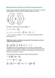
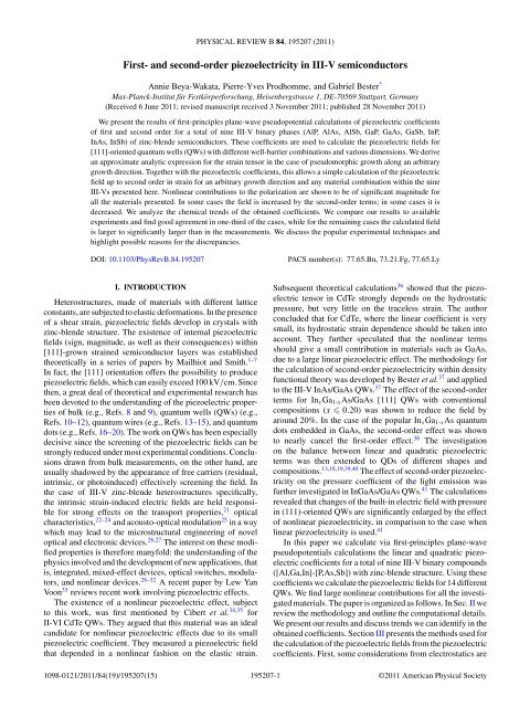
BEYA-WAKATA, PRODHOMME, AND BESTER PHYSICAL REVIEW B 84, 195207 (2011)TABLE I. L<strong>in</strong>ear <strong>and</strong> quadratic piezoelectric coefficients (C/m 2 ) as calculated from LDA-DFT. We report the lattice constant (bohr) atwhich the calculation has been done. The materials accompanied with an asterisk are uncerta<strong>in</strong>, <strong>and</strong> the uncerta<strong>in</strong>ty is put <strong>in</strong>to square bracketsif above our 0.05 C/m 2 precision.e 14 B 114 B 124 B 156 a 0 a exp0 e exp14AlP −0.033 −1.9 −2.7 −1.3 10.222 10.301 UnknownAlAs −0.048 −1.5 −2.6 −1.2 10.619 10.699 UnknownAlSb −0.084 −0.7 −2.2 −0.7 11.478 11.594 0.157, 0.068GaP −0.131 −0.7 −3.6 −0.9 10.235 10.273 −0.15GaAs −0.238 −0.4 −3.8 −0.7 10.645 10.683 −0.16GaSb* −0.247 0.2 [±0.1] −3.2 [±0.1] 0.0 11.378 11.519 −0.12InP 0.003 −1.1 −3.8 −0.5 11.042 11.090 UnknownInAs* −0.115 −0.6 [±0.1] −4.1 0.2 11.432 11.449 −0.045, −0.12InSb* −0.159 0.1 −3.5 0.6 12.141 12.243 −0.071, −0.097C. Reduction of the number of calculation <strong>and</strong> consistencychecks based on symmetry considerationsThe step-by-step methodology used to calculate the <strong>second</strong><strong>order</strong> piezoelectric coefficients was described <strong>in</strong> Sec. II A.However, it is convenient to calculate the coefficients of<strong>in</strong>terest by notic<strong>in</strong>g the specific symmetry of the <strong>second</strong>-<strong>order</strong>tensor (presented <strong>in</strong> Sec. II A). By consider<strong>in</strong>g a [111] shearstra<strong>in</strong> η = (0,0,0,δ,δ,δ)<strong>in</strong>Eq.(3), one is able to obta<strong>in</strong> <strong>in</strong> onecalculation ẽ 11 (δ) = ẽ 11 (η 4 ), ẽ 12 (δ) = ẽ 12 (η 5 ), <strong>and</strong> ẽ 15 (δ) =ẽ 15 (η 6 ), which gives, after correction, the proper coefficientB 114 , B 124 , B 156 .However, apply<strong>in</strong>g different deformations to obta<strong>in</strong> one<strong>second</strong>-<strong>order</strong> coefficient serves as a consistency check. For<strong>in</strong>stance, the relationB 141 = B 114 (17)must hold <strong>and</strong> can be checked by calculat<strong>in</strong>g the η 1 dependenceof e 14 <strong>and</strong> the η 4 dependence of e 11 . In this case, no correctionis required <strong>and</strong> the l<strong>in</strong>ear slopes of these dependencesgive the proper <strong>second</strong>-<strong>order</strong> coefficients, <strong>and</strong> they must beequal. So with only few calculations with hydrostatic <strong>and</strong>uniaxial stra<strong>in</strong>s, it is possible to calculate the three nonl<strong>in</strong>earcoefficients <strong>and</strong> check them.the n<strong>in</strong>e materials. All four coefficients seem to underlie adifferent trend: For e 14 the coefficients become larger alongthe series phosphide → arsenide → antimonide. There is norecognizable trend along Al → Ga → In. The magnitude ofe 14 is largest for the Ga compounds. For B 114 the trend seemsreversed <strong>and</strong> the coefficients go from large to small (evenfrom positive to negative for the In <strong>and</strong> Ga compounds) <strong>in</strong>the direction Sb → As → P. For B 124 the trend follows Al →Ga → In with <strong>in</strong>creas<strong>in</strong>g magnitudes; qualitatively differentthan the trends for e 14 <strong>and</strong> B 114 . The trend for B 156 is yetanother one <strong>and</strong> goes across the series, go<strong>in</strong>g from a positivecoefficient for InSb (0.6) to a negative one for AlP (−1.3),seem<strong>in</strong>gly follow<strong>in</strong>g the mass or the lattice constant of thecompound. To highlight this trend we plotted <strong>in</strong> Fig. 2 thepiezoelectric coefficients as a function of the compound’se 14 B 114D. ResultsThe numerical values of the first- <strong>and</strong> <strong>second</strong>-<strong>order</strong> piezoelectriccoefficients are given <strong>in</strong> Table I along with the latticeconstant (<strong>in</strong> Bohr) at which the calculations were performed.The materials with zero b<strong>and</strong> gap <strong>in</strong> the calculations aremarked with an asterisk <strong>and</strong> the error bars are given <strong>in</strong> squarebrackets. In the last two columns, the experimental values ofthe lattice constant <strong>and</strong> the l<strong>in</strong>ear piezoelectric constant arereported. A graphical representation of these results is given<strong>in</strong> Fig. 1. The n<strong>in</strong>e <strong>semiconductors</strong> are arranged accord<strong>in</strong>g tothe Periodic Table on a grid <strong>and</strong> the height of the columnsis given by the negative value of the coefficients. The colorsare distributed for each panel (coefficient) from blue to redaccord<strong>in</strong>g to the magnitude of the coefficients, blue be<strong>in</strong>gattributed to the smallest. We can see large variations with<strong>in</strong>the n<strong>in</strong>e <strong>III</strong>-V’s <strong>in</strong> the value of the coefficients for e 14 ,B 114 , <strong>and</strong> B 156 with even some changes <strong>in</strong> sign. In contrast,the magnitudes of B 124 are large <strong>and</strong> rather constant forB 124 B 156In Ga AlP As SbFIG. 1. (Color onl<strong>in</strong>e) Graphical display of the piezoelectriccoefficients. The height of the columns (also <strong>in</strong>dicated by the colorcode, from blue to red) give the negative values of the coefficients.195207-4
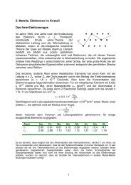
FIRST- AND SECOND-ORDER PIEZOELECTRICITY IN ... PHYSICAL REVIEW B 84, 195207 (2011)Coefficients (C/m 2 )0-1-2-3-4GaPAlPAlAsGaAsInPGaSbInAsAlSbe 14B 114B 124B 15610.4 10.8 11.2 11.6 12Lattice constant (bohr)InSbFIG. 2. (Color onl<strong>in</strong>e) Piezoelectric coefficients as a function ofthe lattice constants.lattice constants. A relatively clear trend with lattice constantcan be only observed for B 156 as just noted.As for the importance of the <strong>second</strong>-<strong>order</strong> coefficients wepresent calculations on QWs made of the different materials.However, from the coefficients alone, we can anticipate thatfor materials with very small e 14 <strong>and</strong> large <strong>second</strong>-<strong>order</strong>coefficients, such as the alum<strong>in</strong>ides <strong>and</strong> InP, the nonl<strong>in</strong>eareffects will dom<strong>in</strong>ate the piezoelectric properties.To gauge the effect of the chosen exchange correlationfunction, we performed additional calculations us<strong>in</strong>g the GGA.The results are given <strong>in</strong> Table II. We see that the value of theB’s for LDA <strong>and</strong> GGA are comparable, while the values of e 14are quite different. This difference is attributed to the valuesused for the lattice constant <strong>in</strong> both approximations. The GGAleads for GaAs <strong>and</strong> InAs to lattice constants significantly largerthan the experimental values so that we assess the LDA valuesas more accurate. In general, the calculated lattice constantsreported <strong>in</strong> Table I are <strong>in</strong> good agreement with experiment.We also note significant discrepancies with previouslycalculated B 156 coefficients 37 for InAs <strong>and</strong> GaAs. For GaAs,our present value (−0.763 C/m 2 ) is around 50% larger <strong>in</strong>magnitude than the earlier value (−0.492 C/m 237 ) <strong>and</strong> forInAs even the sign is opposite (0.156 here vs −0.120 earlier 37 ).TABLE II. L<strong>in</strong>ear <strong>and</strong> quadratic piezoelectric coefficients (C/m 2 )as calculated from GGA-DFT. The lattice constant (bohr) at whichthe calculation has been done is reported <strong>in</strong> the last column <strong>and</strong> issignificantly larger than reported experimentally. We discard theseresults as less accurate.e 14 B 114 B 124 B 156 a 0GaAs −0.342 −0.5 −4.1 −0.6 10.948InAs −0.241 −0.5 −4.4 0.1 11.764The facts that the rema<strong>in</strong><strong>in</strong>g coefficients are <strong>in</strong> excellentagreement with this previous work 37 <strong>and</strong> that we do notsee fluctuations of nearly that magnitude by us<strong>in</strong>g differentlevels of approximation (pseudopotentials used <strong>and</strong> exchangecorrelation functional), leads us to believe that the previousresults must have been erroneous. A negative B 156 coefficientfor InAs was obta<strong>in</strong>ed <strong>in</strong>dependently. 52E. Accuracy of the results <strong>and</strong> issues with zero-gap materialsOverall, the electronic structure parameters (number of kpo<strong>in</strong>ts, energy cutoff) were chosen to reach an accuracy of0.05 C/m 2 on the B’s.However, s<strong>in</strong>ce DFT (LDA or GGA) is well knownto estimate roughly the electronic b<strong>and</strong> dispersion, <strong>and</strong> <strong>in</strong>particular it underestimates the b<strong>and</strong> gap, it happens <strong>in</strong> ourcalculations that for some materials with small gap (GaSb,InAs, InSb) the gap was found to be null. For those materials,despite all the care we took to ensure convergence (k po<strong>in</strong>ts,cutoff, relaxation, etc.), we obta<strong>in</strong> discrepancies betweencoefficients that must be identical on symmetry grounds (underVoigt <strong>in</strong>dices <strong>in</strong>terchange). We <strong>in</strong>terpret these discrepanciesas aris<strong>in</strong>g from the self-consistent change of the density, <strong>in</strong>response to the applied stra<strong>in</strong>, that can be affected by thepathological situation of vanish<strong>in</strong>g b<strong>and</strong> gaps. For example,for the GaSb compound, we f<strong>in</strong>d B 114 = 0.30 C/m 2 <strong>and</strong>B 141 = 0.18 C/m 2 , although these should be equal. So forthis material we reta<strong>in</strong> only the average value <strong>and</strong> we considerthe error as the difference between the two values; this is±0.12 C/m 2 . This value is given as error bars <strong>in</strong> our f<strong>in</strong>alresults. For these materials, we also have reasons to doubtthe accuracy of the l<strong>in</strong>ear coefficients. Us<strong>in</strong>g pseudopotentialswithout d states opens the b<strong>and</strong> gap <strong>and</strong> changes the resultsfor e 14 quite dramatically (for InAs, the coefficient changesfrom −0.115 to +0.066 C/m 2 ) while this change is smallerfor materials with nonzero b<strong>and</strong> gap at the LDA level. Thesechanges are tied with the strong dependence on the latticeconstant (that is just given by the B’s) <strong>and</strong> it is difficult toestimate an error bar. Our impression, however, is that thel<strong>in</strong>ear coefficients for materials with zero gap <strong>in</strong> LDA/GGAmay be improved by methods yield<strong>in</strong>g a proper b<strong>and</strong> gap (e.g.,GW), not available at the moment.F. Harrison model of <strong>piezoelectricity</strong>Here we give a short <strong>in</strong>troduction to the popular Harrisonmodel of <strong>piezoelectricity</strong> which gives an <strong>in</strong>tuitive picture of<strong>piezoelectricity</strong>. Harrison 53 followed the idea of the bondorbitalmodel. 54 He def<strong>in</strong>ed the microscopic electric dipoleof a pair of anion-cation <strong>in</strong>duced by a lattice deformation η 4as the piezoelectric dipole p:p = δd e ∗ P e with δd = ξη 4a/8, (18)with a the lattice constant, eP∗ the so-called piezoelectriccharge, <strong>and</strong> e the electron charge. The <strong>in</strong>ternal displacementof the metallic relative to the nonmetallic atom is given byδd. Without any change <strong>in</strong> the physics it is rewritten for az<strong>in</strong>c-blende structure us<strong>in</strong>g the Kle<strong>in</strong>man parameter ξ. Thepiezoelectric charge eP∗ is also commonly rewritten us<strong>in</strong>g195207-5
BEYA-WAKATA, PRODHOMME, AND BESTER PHYSICAL REVIEW B 84, 195207 (2011)parameters from the bond-orbital model aseP ∗ = Z∗ − 8α ( )p 1 − α2p (1 − ξ), (19)3ξwhere Z ∗ is the effective charge of the material <strong>and</strong> α pthe polarity of the bond, both orig<strong>in</strong>ally def<strong>in</strong>ed based ona l<strong>in</strong>ear comb<strong>in</strong>ation of atomic orbitals model. 54 S<strong>in</strong>ce Z ∗can be directly related to α 54 p this model of <strong>piezoelectricity</strong>requires only two parameters, namely, ξ <strong>and</strong> α p . Whilethese parameters have an <strong>in</strong>tuitive mean<strong>in</strong>g, they cannot bemeasured or calculated directly. They are usually extractedfrom some experimental quantities <strong>and</strong> can then be reused topredict other quantities. In the orig<strong>in</strong>al work of Harrison 53 thecalculated piezoelectric charge eP ∗ was <strong>in</strong> poor agreement withthe values deduced from experimental piezoelectric constants.However, this is not surpris<strong>in</strong>g s<strong>in</strong>ce the piezoelectric responseis a delicate balance between a clamped-ion part <strong>and</strong> an<strong>in</strong>ternal-stra<strong>in</strong> part 55 that depend sensitively on the chosenparameter. Indeed, an adjustment of the parameters br<strong>in</strong>gsexperiment <strong>and</strong> theory <strong>in</strong> agreement (at the expense to br<strong>in</strong>gabout a disagreement with the experiment from which theparameters were extracted from orig<strong>in</strong>ally). The benefit of themodel lies <strong>in</strong> its simplicity <strong>and</strong> the <strong>in</strong>tuitive picture it draws.The generality of Eq. (18) makes it possible to <strong>in</strong>troduce stra<strong>in</strong>dependence beyond the trivial l<strong>in</strong>ear term <strong>in</strong> δd. This has beenrecently done by Migliorato et al. 56 for In x Ga 1-x As. In thiswork, the bond polarity α p was taken from a tight-b<strong>in</strong>d<strong>in</strong>gmodel <strong>and</strong> the Kle<strong>in</strong>man parameters were calculated by DFT.The effective charges Z ∗ of InAs <strong>and</strong> GaAs were not calculatedfrom α 54 p but were used as fitt<strong>in</strong>g parameters to reproduce theexperimentally determ<strong>in</strong>ed piezoelectric coefficients of bulkInAs <strong>and</strong> GaAs. Us<strong>in</strong>g the same stra<strong>in</strong> dependence for α p <strong>and</strong>Z ∗ <strong>and</strong> a l<strong>in</strong>ear <strong>in</strong>terpolation between different compositions,the piezoelectric charge <strong>and</strong> hence coefficient, show a bow<strong>in</strong>gtoward less negative values, compared to a treatment l<strong>in</strong>ear <strong>in</strong>stra<strong>in</strong>. This bow<strong>in</strong>g is <strong>in</strong> agreement with our ab <strong>in</strong>itio resultswhere the <strong>second</strong>-<strong>order</strong> terms make the effective piezoelectriccoefficient less negative.<strong>III</strong>. CALCULATION OF PIEZOELECTRIC FIELDSIN QUANTUM WELLSA. Considerations from electrostaticsFrom the electrostatic equations of dielectrics the displacementfield D is <strong>in</strong>troduced asD = ε 0 E + P, (20)with the electronic polarization P describ<strong>in</strong>g the electronicresponse to the applied external field E. Us<strong>in</strong>g the permittivitytensor,ε ≡ ε αβ = 1 ∂ D α, (21)ε 0 ∂ E βwe obta<strong>in</strong>P = ε 0 (ε − 1)E + P 0 , (22)where P 0 <strong>and</strong> ε 0 are the zero-electric-field polarization <strong>and</strong> thepermittivity of the vacuum, respectively. Assum<strong>in</strong>g a l<strong>in</strong>earrelation between the applied electric field <strong>and</strong> the ensu<strong>in</strong>gelectronic polarization <strong>and</strong> an isotropic medium, we canrewrite itP = ε 0 χ e E + P 0 , (23)us<strong>in</strong>g the electrical susceptibility tensor χ e = ε − 1. Thepolarization P 0 can only be nonzero if the medium lacks<strong>in</strong>version symmetry. In the case of a piezoelectric materialthis is the case <strong>and</strong> an additional polarization emerges asgiven <strong>in</strong> Eq. (2), written here as a sum of l<strong>in</strong>ear <strong>and</strong> <strong>second</strong><strong>order</strong>(<strong>in</strong> stra<strong>in</strong>) terms: P pz = P pz1 + P pz2. Follow<strong>in</strong>g Eq. (23)this piezoelectric polarization is def<strong>in</strong>ed theoretically as theresponse function under vanish<strong>in</strong>g macroscopic field E = 0,<strong>and</strong> this is the way it is calculated with<strong>in</strong> DFT. This is arather theoretical concept s<strong>in</strong>ce <strong>in</strong> a crystal an electric field willemerge from the polarization charges. This field would haveto be explicitly short-circuited, to fulfill the E = 0 condition,which is probably difficult to realize. A discussion on this po<strong>in</strong>tcan be found, for example, <strong>in</strong> Ref. 57.The displacement fields, polarization, <strong>and</strong> electric fields arerelated <strong>in</strong> first <strong>order</strong> of stra<strong>in</strong> <strong>and</strong> field viaD = ε 0 E + P,P = ε 0 χ e E + P pz1 ,D = ε 0 E + ε 0 χ e E + P pz1 = ε 0εE + P pz1 ,<strong>and</strong> up to <strong>second</strong> <strong>order</strong> <strong>in</strong> both stra<strong>in</strong> <strong>and</strong> field viaD = ε 0 E + P,P = ε 0 χ e E + ε 0 χ ′ e E2 + P pz1 + P pz2 ,D = ε 0 E + ε 0 χ e E + ε 0 χ ′ e E2 + P pz1 + P pz2 ,D = ε 0 εE + ε 0 χ ′ e E2 + P pz1 + P pz2 .Now two possible experimental situations can occur. If thesample is short circuited E = 0 <strong>and</strong> if it is electrically isolatedD = 0. For the latter case we obta<strong>in</strong> <strong>in</strong> first <strong>order</strong>ε 0 εE =−P pz1 , (24)<strong>and</strong> <strong>in</strong> <strong>second</strong> <strong>order</strong> we obta<strong>in</strong>0 = ε 0 εE + ε 0 χ ′ e E2 + P pz1 + P pz2 , (25)which would require the calculation of the <strong>second</strong>-<strong>order</strong>electric susceptibility tensor:χ ′ e ≡ χ αβγ ′ = 1 ∂P α. (26)ε 0 ∂E β ∂E γWe neglect the term of <strong>second</strong> <strong>order</strong> <strong>in</strong> the field <strong>and</strong> writeε 0 εE =−P pz1 − P pz2 .Note that the stress <strong>and</strong> the electric field are coupled via theNavier equation:T = cS − ẽE, (27)where T is the stress tensor, c the stiffness tensor, ẽ thepiezoelectric tensor, <strong>and</strong> E the electric field. 33 We neglectthis coupl<strong>in</strong>g, which has been shown to be small. 33We apply this formalism to the case of superlattices or QWs,which are structures with periodicity <strong>in</strong> the growth plane. Inthis case ∂/∂ x = ∂/∂ y = 0(ifx,y are <strong>in</strong> the growth plane) <strong>and</strong>from Maxwell’s equations we obta<strong>in</strong> for the <strong>in</strong>-plane electricfield, E ‖ = 0. Hence, the electric field is parallel or antiparallelto the growth direction <strong>and</strong> if the dielectric tensor is diagonal195207-6
FIRST- AND SECOND-ORDER PIEZOELECTRICITY IN ... PHYSICAL REVIEW B 84, 195207 (2011)(as <strong>in</strong> the z<strong>in</strong>c blende structure), only the projection of thepolarization along the growth axis is relevant.B. Special case of a [111] quantum wellFor z<strong>in</strong>c-blende <strong>III</strong>-V semiconductor materials, stra<strong>in</strong> alongthe [111] axis represents an important case s<strong>in</strong>ce the polarizationP <strong>and</strong> the piezoelectric field E are directed along thedirection of growth (which is not generally the case) <strong>and</strong> thepiezoelectric field is usually the largest (this is only formallytrue if <strong>second</strong>-<strong>order</strong> effects are neglected, but even consider<strong>in</strong>g<strong>second</strong>-<strong>order</strong> effect it is true <strong>in</strong> most of the cases). Moreover,the overwhelm<strong>in</strong>g majority of previous <strong>in</strong>vestigations wereperformed on structures grown on the (111)-oriented surface.The field <strong>and</strong> polarization can be reduced to scalar quantitiesE <strong>and</strong> P s<strong>in</strong>ce polarization <strong>and</strong> electric field are parallel orantiparallel to the growth axis. Us<strong>in</strong>g first-<strong>order</strong> terms <strong>in</strong> stra<strong>in</strong>for the piezoelectric polarization the piezoelectric field <strong>in</strong> thewell can be calculated from Eq. (4). The stra<strong>in</strong> tensor <strong>in</strong> thisgeometry has the follow<strong>in</strong>g properties: η 4 = η 5 = η 6 ,η 1 =η 2 = η 3 , <strong>and</strong> the polarization can be written asPl 111 = √ 3e 14 η 4 = 2 √ 3e 14 η xy . (28)The shear stra<strong>in</strong> can be calculated for pseudomorphic growthfrom the elastic constants C ij : 58whereC 11 + 2C 12η xy =−ε ‖ , (29)C 11 + 2C 12 + 4C 44ε ‖ = δa a = a sub − a well, (30)a wellwhere a sub <strong>and</strong> a well are the lattice constants of the substrate <strong>and</strong>the well, respectively. Investigat<strong>in</strong>g all the material propertiesenter<strong>in</strong>g <strong>in</strong> Eqs. (28) <strong>and</strong> (24), we see that the l<strong>in</strong>ear regimeis appropriate for the dielectric constant 59 given the electricfield values <strong>in</strong>volved (hundreds of kV/cm), <strong>and</strong> the elasticcoefficients for stra<strong>in</strong> values up to 2%. 36 The only rema<strong>in</strong><strong>in</strong>gsource of possible nonl<strong>in</strong>earity is then the piezoelectricconstant.Consider<strong>in</strong>g the quadratic dependence of the piezoelectricpolarization <strong>in</strong> stra<strong>in</strong> <strong>in</strong>volves the use of both diagonal <strong>and</strong>traceless stra<strong>in</strong> components [Eq.(4)]. For [111] growth, thediagonal components can be calculated from the elasticconstants as well:4C 44η xx = η yy = η zz =ε ‖ , (31)C 11 + 2C 12 + 4C 44<strong>and</strong> the off-diagonal components are η xy = η xz = η yz ,asgiven<strong>in</strong> Eq. (29).The polarization from Eq. (2) along the [111] directionbecomesP 111 = √ 3 [e 14 η 4 + (B 114 η 1 + 2B 124 η 2 ) η 4 + B 156 η 5 η 6 ] ,(32)with a l<strong>in</strong>ear part given by Pl111 = √ 3e 14 η 4 <strong>and</strong> a nonl<strong>in</strong>earterm: Pnl111 = √ 3(B 114 η 1 + 2B 124 η 2 )η 4 + B 156 η 5 η 6 . Note thatthe polarization P 111 can be positive or negative if it is parallelor antiparallel to the [111] crystallographic direction.For ternary compounds we use Vegard’s law for the latticeparameters. For the elastic constants, deformation potentials<strong>and</strong> piezoelectric constants we <strong>in</strong>terpolated between bulkvalues.C. General case of a quantum well grown alongan arbitrary directionWe describe how to obta<strong>in</strong> the stra<strong>in</strong> tensor <strong>in</strong> Cartesiancoord<strong>in</strong>ates for a layered z<strong>in</strong>c-blende structure pseudomorphicallygown on a substrate for arbitrary crystallographic growthdirections. Pseudomorphic growth means that a semiconductorof lattice constant a well is grown on a substrate of latticeconstant a sub . The atomic layers of lattice constant a well on thesubstrate are fac<strong>in</strong>g compressive or tensile stra<strong>in</strong> [depend<strong>in</strong>gon the sign of (a sub − a well )] <strong>in</strong> the growth plane. In thegrowth direction, the layered z<strong>in</strong>c-blende structure (the well)is allowed to relax <strong>and</strong> will do so, accord<strong>in</strong>g to the elasticproperties of the material, fully described by the the fourthrankelastic tensor C αβγ δ . To calculate the stra<strong>in</strong> tensor forarbitrary growth direction (hkl), where h,k,l are the Miller<strong>in</strong>dices, we proceed as follows.(1) We def<strong>in</strong>e a rotation matrix R αβ that transforms theCartesian coord<strong>in</strong>ate system to a coord<strong>in</strong>ate system wherethe (hkl) direction represents the z ′ direction, with x ′ <strong>and</strong>y ′ orthogonal to it <strong>and</strong> to each other.(2) In this primed coord<strong>in</strong>ate system, five of the six<strong>in</strong>dependent stra<strong>in</strong> tensor elements can be simply derivedby symmetry arguments: η xx ′ = η′ yy = δa/a, η′ xy = 0, <strong>and</strong>η xz ′ ≠ η′ yz ≠ 0. The analytic expressions for η′ xz <strong>and</strong> η′ yz canbe found <strong>in</strong> Refs. 60–62 <strong>and</strong> are not reproduced here. The lastelement, η zz ′ , can be obta<strong>in</strong>ed by impos<strong>in</strong>g a vanish<strong>in</strong>g stressalong the growth direction. The stress <strong>and</strong> the stra<strong>in</strong> tensors areconnected via σ αβ ′ = C′ αβγ δ η′ γδ , which leads to the expressionη zz ′ =−C′ 3311 + C′ 3322δaC3333′ a . (33)(3) The rotated elastic constants needed <strong>in</strong> Eq. (33) areobta<strong>in</strong>ed via the Von Neumann relation of the tensor rotation,C αβγ ′ δ = R αλR βμ R γν R δξ C λμνξ .(4) Now that the stra<strong>in</strong> tensor <strong>in</strong> the primed coord<strong>in</strong>atesystem is fully def<strong>in</strong>ed, we obta<strong>in</strong> it <strong>in</strong> the unrotated Cartesiancoord<strong>in</strong>ates via η αβ = R −1αλ R−1 βμ η′ λμ , where the <strong>in</strong>verse of arotation matrix is simply its transpose. Unfortunately, verylengthy expressions are obta<strong>in</strong>ed follow<strong>in</strong>g this procedure. Inthe Appendix, we give the general analytic expression for thestra<strong>in</strong> tensor we obta<strong>in</strong> assum<strong>in</strong>g η xz ′ = η′ yz = 0, <strong>and</strong> discusshow severe this approximation is. The stra<strong>in</strong> tensors for specificcommon orientations have a rather simple form given as [111]QW θ = tan −1 [ √ 2], φ = π/4,4C 44 δaη xx = η yy = η zz =C 11 + 2C 12 + 4C 44 a , (34)η xy = η xz = η yz =− (C 11 + 2C 12 ) δaC 11 + 2C 12 + 4C 44 a ; (35)[100] QW θ = π/2, φ = 0,η xx =− 2C 12C 11δaa , (36)195207-7
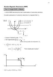
BEYA-WAKATA, PRODHOMME, AND BESTER PHYSICAL REVIEW B 84, 195207 (2011)η yy = η zz = δa a , (37)η xy = η xz = η yz = 0; (38)[110] QW θ = π/2, φ = π/4,η xx = η yy =− (C 12 − 2C 44 ) δaC 11 + C 12 + 2C 44 a , (39)η zz = δa a , (40)η xy =− (C 11 + 2C 12 ) δaC 11 + C 12 + 2C 44 a , (41)η xz = η yz = 0. (42)D. Electrostatic boundary conditions <strong>and</strong>quantum well superlatticesIn [111]-oriented QW superlattices the polarization alongthe growth direction is piecewise constant <strong>in</strong> the barrier<strong>and</strong> <strong>in</strong> the well. This is equivalent to a distribution ofpiezoelectric bound charges conf<strong>in</strong>ed to sheets of charges withuniform density −P on one type of <strong>in</strong>terface <strong>and</strong> +P onthe other. The system thus behaves as an array of parallelcapacitors. Us<strong>in</strong>g the <strong>in</strong>tegral version of Maxwell’s equation<strong>and</strong> apply<strong>in</strong>g periodic boundary conditions, which means thesuperlattice is short circuited <strong>in</strong> the growth direction, the<strong>in</strong>duced piezoelectric field <strong>in</strong> the wells readsE =− P L − t, (43)ε 0 tε b + (L − t)ε wwhere t is the thickness of the well, L the period of thesuperlattice, <strong>and</strong> ε b <strong>and</strong> ε w the static dielectric constants of thebarrier <strong>and</strong> the well materials, respectively. Assum<strong>in</strong>g D = 0,which is valid for an isolated sample with no free charges, weobta<strong>in</strong>E =− P , (44)ε w ε 0which also represents the limit<strong>in</strong>g case of Eq. (43) for an<strong>in</strong>f<strong>in</strong>ite barrier.IV. RESULTS FOR PIEZOELECTRIC FIELDS IN [111]QUANTUM WELLSUs<strong>in</strong>g the piezoelectric coefficients <strong>and</strong> the elastic constantsgiven <strong>in</strong> Table <strong>III</strong> we can calculate the piezoelectric fieldsfor different material comb<strong>in</strong>ations. From all the possible 72comb<strong>in</strong>ations between the n<strong>in</strong>e <strong>III</strong>-Vs <strong>semiconductors</strong> we havechosen 14 based on the requirement of lattice mismatch <strong>and</strong>the popularity of the material system. The barrier is takenas <strong>in</strong>f<strong>in</strong>itely thick, follow<strong>in</strong>g Eq. (44). We show the results <strong>in</strong>Fig. 3 <strong>in</strong> the form of bar charts, where we use the notation A/Bto describe material A lattice matched to material B.Weusedpure materials, although some comb<strong>in</strong>ations are impossibleto grow due to the large lattice mismatch. This figure isclearly an illustration of the effect. The field for a specificQW composition <strong>and</strong> geometry can be easily calculated fromthe coefficients. The field us<strong>in</strong>g l<strong>in</strong>ear coefficients only is givenfor each QW by the left bar <strong>and</strong> the field <strong>in</strong>clud<strong>in</strong>g l<strong>in</strong>ear <strong>and</strong>quadratic terms by the right bar. The effects of the quadraticTABLE <strong>III</strong>. Elastic constants <strong>in</strong> units of 10 11 dyne cm −2 calculatedvia DFT <strong>and</strong> used <strong>in</strong> the calculation of the piezoelectric fields<strong>in</strong> QWs.AlP AlAs AlSb GaP GaAs GaSb InP InAs InSbC 11 13.29 11.22 8.56 14.06 11.33 8.92 9.89 8.28 6.70C 12 6.75 5.53 4.25 6.18 5.08 3.97 5.56 4.66 3.63C 44 6.29 5.43 3.96 6.90 5.68 4.43 4.47 3.74 3.05terms is very large for all the structures, sometimes revers<strong>in</strong>gthe sign of the field (InAs/GaAs, InSb/GaSb, InP/InAs,InAs/InP, InSb/InAs). Some structures have very small fieldsif only the l<strong>in</strong>ear terms are accounted for (InP/GaP, InP/InAs)but have significant fields tak<strong>in</strong>g <strong>second</strong>-<strong>order</strong> coefficients<strong>in</strong>to account. Some QWs exhibit very large fields up to fewMV/cm, such as GaP/InP or GaAs/InAs.V. RESULTS FOR PIEZOELECTRIC FIELDS ININ x GA 1-x AS/GAAS QUANTUM WELLS FORARBITRARY GROWTH DIRECTIONWe have expressed the polarization from Eq. (2) <strong>in</strong> sphericalcoord<strong>in</strong>ates us<strong>in</strong>g the general form of the stra<strong>in</strong> tensor forpseudomorphic growth, as described <strong>in</strong> Sec. <strong>III</strong> C. This allowsus to calculate the polarization for any growth direction (hkl).From the polarization we obta<strong>in</strong> the piezoelectric field us<strong>in</strong>gEq. (43), where the scalar P is the projection of the polarizationon the vector r,P = P · ˆr,where ˆr is along the growth direction <strong>and</strong> is given as afunction of Euler angles as (s<strong>in</strong> θ cos φ, s<strong>in</strong> θ s<strong>in</strong> φ, cos θ).In this section, we show results for an In x Ga 1-x As QWwith a thickness of 10 nm, pseudomorphically grown onGaAs. For the dielectric constants we used ε InAs = 15.15 <strong>and</strong>ε GaAs = 12.90. The elastic, lattice, <strong>and</strong> dielectric constants areElectric Field (kV/cm)20001000-1000-2000-3000-4000-5000GaP/GaAsGaAs/GaPGaP/InPInP/GaPGaAs/InAsInAs/GaAsGaAs/GaSbGaSb/GaAsGaSb/InSbInSb/GaSbInP/InAsInAs/InPInAs/InSbInSb/InAsl<strong>in</strong>nonl<strong>in</strong>FIG. 3. (Color onl<strong>in</strong>e) Bar charts of the piezoelectric fields for14 different QWs A/B, where the material A is stra<strong>in</strong>ed to thelattice constant of material B. The barrier is taken as <strong>in</strong>f<strong>in</strong>itely thick[Eq. (44)]. The left (right) bar for each QW represents the result tak<strong>in</strong>gonly the l<strong>in</strong>ear (both the l<strong>in</strong>ear <strong>and</strong> quadratic) term(s) <strong>in</strong>to account.195207-8
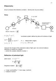
FIRST- AND SECOND-ORDER PIEZOELECTRICITY IN ... PHYSICAL REVIEW B 84, 195207 (2011)L<strong>in</strong>ear OnlyInAs(a)[111][101]Up to <strong>second</strong> <strong>order</strong> <strong>in</strong> stra<strong>in</strong>In 20Ga 80As In 40Ga 60As In 60Ga 40As In 80Ga 20As InAs[110][100](b)14|P|[111] (mC/m 2 ): 4 4 0 8 20819E[111] (kV/cm): 249 259 28 -447 -1169FIG. 4. (Color onl<strong>in</strong>e) Spherical polar plots of the magnitude of the polarization (a) <strong>and</strong> of the piezoelectric field (b) <strong>in</strong> pseudomorphicIn x Ga 1-x As/GaAs QWs of arbitrary crystallographic orientation. The wells are 10 nm wide <strong>and</strong> surrounded by 30-nm GaAs barriers. The Eulerangles θ <strong>and</strong> φ give the direction of the growth axis accord<strong>in</strong>g to Eqs. (A1), <strong>and</strong> at the same time the orientation of the piezoelectric field.The radial dimension of the spherical polar plot gives the absolute value of the length of the polarization vector (a) <strong>and</strong> the piezoelectric fieldalong the growth direction (b). The blue <strong>and</strong> red colors <strong>in</strong> (b) <strong>in</strong>dicate if the field is oriented parallel or antiparallel to the growth direction,respectively. The numerical values of the magnitude of the polarization <strong>and</strong> of the piezoelectric fields along the [111] direction are given atthe bottom of each plot. Note that the field E [111] (for [111] growth) is oriented along the growth direction for In concentrations up to 60%but is reversed for 80% <strong>and</strong> 100% In concentrations. The spherical polar plots consider<strong>in</strong>g only the l<strong>in</strong>ear term are qualitatively the same forall concentrations <strong>and</strong> only the pure InAs case is shown on the left. With l<strong>in</strong>ear term only for the concentrations 20%, 40%, 60%, 80%, 100%the values of the field are 324, 561, 720, 804, 819 kV/cm, respectively, <strong>and</strong> for the magnitudes of the polarizations we obta<strong>in</strong> 5, 9, 12, 13,14 mC/cm 2 .averaged between bulk values when we calculate the r<strong>and</strong>omalloys. In Fig. 4(a) we have plotted the magnitude of thepolarization <strong>in</strong> a spherical polar plot where the Euler anglesθ <strong>and</strong> φ give the direction of the growth axis accord<strong>in</strong>g toEqs. (A1). In a similar fashion we have plotted <strong>in</strong> Fig. 4(b) thepiezoelectric field <strong>in</strong>clud<strong>in</strong>g only the l<strong>in</strong>ear term [leftmost plot<strong>in</strong> Fig. 4(b)] <strong>and</strong> also <strong>in</strong>clud<strong>in</strong>g the l<strong>in</strong>ear <strong>and</strong> nonl<strong>in</strong>ear termsfor various In concentrations. On the grounds of symmetry,the polarization vanishes for the {100} directions. If only thel<strong>in</strong>ear terms are <strong>in</strong>cluded, the magnitude of the polarizationshows sharp dips around the {100} directions but, aside fromthese steep depressions, is rather homogeneous. For <strong>in</strong>stance,the difference between the magnitude of the polarization alongthe [111] <strong>and</strong> [110] directions is only 8%. The piezoelectricfield <strong>in</strong> Fig. 4(b) is qualitatively different as it vanishes alsoalong the {110} directions. In this case the polarization isperpendicular to the growth direction <strong>and</strong> does not allow for thefield to develop. So the {100} directions are nonpiezoelectricbecause of the symmetry of the stra<strong>in</strong> tensor (no shear stra<strong>in</strong>components), while the {110} directions are nonpiezoelectricbecause the polarization is orthogonal to the growth direction.If only the l<strong>in</strong>ear terms are considered, the shape of the polarplots of the polarization <strong>and</strong> field do not change qualitatively,when chang<strong>in</strong>g the concentration, <strong>and</strong> we therefore show onlyone image for the pure InAs case. The magnitude of thepolarization <strong>and</strong> field, however, does <strong>in</strong>creases as the stra<strong>in</strong>becomes larger, mov<strong>in</strong>g to higher In concentrations. We obta<strong>in</strong>for the concentrations x = 0.2, 0.4, 0.6, 0.8, 1.0 the fields 324,561, 720, 804, 820 <strong>in</strong> kV/cm <strong>and</strong> the polarizations 5, 9, 12,13, 14 mC/m 2 along the [111] direction, respectively.Includ<strong>in</strong>g the <strong>second</strong>-<strong>order</strong> terms (six images on the rightof Fig. 4) changes the images qualitatively. At 20% Inconcentration, the shape is still similar to the shape obta<strong>in</strong>edwith l<strong>in</strong>ear coefficients only, although the field has shrunkby 23% (from 324 to 250 kV/cm). Further <strong>in</strong>crease <strong>in</strong>concentration changes the morphology of the surface plot<strong>and</strong> its magnitude. At around 60% the sign of the fieldfor [111]-growth changes, so that the field is now orientedtoward the [¯1¯1¯1] direction. The <strong>second</strong>-<strong>order</strong> terms makethe surface extremely anisotropic. The field along the {111}directions reaches the MV/cm. This represents, however, theextreme case of a pure InAs QW, which cannot be grownpseudomorphically on GaAs. Such values of stra<strong>in</strong> can onlybe obta<strong>in</strong>ed <strong>in</strong> quantum dot structures, 38 but also there thestructures are usually alloyed with overall concentrationsaround 60%. At this concentration the expected field is verysmall (36 kV/cm, much smaller than if only the l<strong>in</strong>ear termswere considered: 720 kV/cm), but it becomes clear that smalldeviations from a nom<strong>in</strong>al composition of 60% will boost upthe piezoelectric field significantly.VI. EXPERIMENTAL DETERMINATIONOF PIEZOELECTRIC FIELDSThe experimental determ<strong>in</strong>ation of the piezoelectric fieldis an <strong>in</strong>tricate <strong>and</strong> <strong>in</strong>direct process. The simple measurement195207-9
BEYA-WAKATA, PRODHOMME, AND BESTER PHYSICAL REVIEW B 84, 195207 (2011)of the deformation of the crystal under applied voltage via<strong>in</strong>terferometric techniques is possible, but the results dependheavily on the sample morphology <strong>and</strong> used apparatus (see,e.g., Ref. 63). Other methods are <strong>in</strong>direct <strong>and</strong> based onapproximations sometimes difficult to gauge. We criticallypresent the most common techniques <strong>and</strong> related issues.A. Determ<strong>in</strong>ation from optical spectraPhotolum<strong>in</strong>escence (PL) has been used extensively to characterizeheterostructures <strong>and</strong> piezoelectric field effects. 64–69In fact, PL <strong>and</strong> absorption spectra give <strong>in</strong>dications aboutthe spatial separation of electrons <strong>and</strong> holes <strong>in</strong> the presenceof stra<strong>in</strong>-<strong>in</strong>duced electric field: The transition probabilitybetween electron <strong>and</strong> hole states <strong>in</strong> a QW is reduced <strong>and</strong>its transition energy is also lowered due to the separation ofelectrons <strong>and</strong> holes <strong>and</strong> the quantum-conf<strong>in</strong>ed Stark effect. Themeasurement of both effects makes it possible, <strong>in</strong> pr<strong>in</strong>ciple,to determ<strong>in</strong>e the built-<strong>in</strong> field. S<strong>in</strong>ce the composition of theQW generally fluctuates, the calculation of one transitionenergy cannot be directly compared with the measurements.The transition energy is therefore measured as a functionof a parameter. Four ma<strong>in</strong> possibilities have been explored:(1) vary<strong>in</strong>g the well width, (2) vary<strong>in</strong>g the QW composition,(3) vary<strong>in</strong>g the optical excitation power <strong>and</strong> hence the densityof screen<strong>in</strong>g charges, 70–74 or (4) apply<strong>in</strong>g an external voltage<strong>and</strong> look<strong>in</strong>g for the flat-b<strong>and</strong> condition, when the PL <strong>in</strong>tensity<strong>and</strong> transition energy are maximum. 63,75–77B. Local m<strong>in</strong>ima lead to <strong>in</strong>terface chargesIn multiquantum well (MQW) structures, the observedblueshifts were attributed to another mechanism. 78 Depend<strong>in</strong>gon the geometry of the structure, an <strong>in</strong>ternal field cansometimes be created across the MQW, giv<strong>in</strong>g rise to localm<strong>in</strong>ima <strong>in</strong> the potential at either end of the MQW <strong>and</strong> trapp<strong>in</strong>gphotogenerated carriers that have escaped from the QWs <strong>and</strong>have drifted to the edges of the MQW region. Many PL<strong>and</strong> time-resolved absorption measurements are consistentwith this model, 78–84 but they do not provide quantitative<strong>in</strong>formation about the <strong>in</strong>ternal position of the screen<strong>in</strong>gcharges. Generally both <strong>in</strong>-well <strong>and</strong> out-of-well screen<strong>in</strong>g canoccur <strong>in</strong> such structures <strong>and</strong>, the estimate of piezoelectric fieldstrength from the variation <strong>in</strong> transition energy only cannotyield reliable results.C. The calculation of transition energies dependson several nontrivial aspectsSeveral processes responsible for both the redshifts <strong>and</strong>the blueshifts can occur simultaneously mak<strong>in</strong>g <strong>in</strong>terpretationof the PL complicated. The redshifts seen at low excitationpower are attributed to the photovoltaic effect <strong>in</strong> piezoelectricstra<strong>in</strong>ed InGaAs-GaAs MQW p-i-n structures, 85 while theblueshifts are attributed to compet<strong>in</strong>g effects of b<strong>and</strong>-gaprenormalization (quantum conf<strong>in</strong>ement), b<strong>and</strong>-state fill<strong>in</strong>g <strong>and</strong>partial carrier screen<strong>in</strong>g of the piezoelectric field <strong>in</strong> InGaAsQWs grown on (111)B (Refs. 28,86, <strong>and</strong> 87) <strong>and</strong> (111)A(Refs. 88 <strong>and</strong> 89) GaAs substrates. However, even at lowoptical power, that is, at negligible carrier densities, bigdifferences still appear <strong>and</strong> are thought to be due to stra<strong>in</strong>relaxation, charge trapp<strong>in</strong>g, <strong>and</strong> defects at the <strong>in</strong>terfaces. 88,89For doped samples, the possibility that the piezoelectric fieldis screened by free charges supplied from the substrate (forexample, n+ GaAs substrate <strong>in</strong> Ref. 90) cannot be completelyruled out. These uncerta<strong>in</strong>ties are probably <strong>in</strong> the same <strong>order</strong>of magnitude as the theoretical uncerta<strong>in</strong>ties for materials witha vanish<strong>in</strong>g gap <strong>in</strong> the LDA or GGA approximations (InAs,GaSb, InSb), as mentioned <strong>in</strong> Sec. II E.D. Dielectric models are often not appropriateAs described, most of the measurements determ<strong>in</strong>e the<strong>in</strong>ternal field. To extract the piezoelectric constant from themeasured value of the field, Eqs. (28) <strong>and</strong> (44) are most oftenused. Accord<strong>in</strong>g to that equation, the piezoelectric field doesneither depend on the layer thickness nor on the barrier width,which is true only for <strong>in</strong>f<strong>in</strong>itely large barriers, or for electricallyisolated wells. This equation is, however, often used for MQWstructures, which is obviously <strong>in</strong>appropriate. From Eq. (43) itis clear that well <strong>and</strong> barrier thicknesses are very much relevant<strong>in</strong> these cases. One must also realize that Eq. (43) represents<strong>in</strong> most cases an approximation as well. The determ<strong>in</strong>ationof the electric field <strong>in</strong> the well requires the solution of theelectrostatic problem with the appropriate boundary conditions<strong>and</strong> tak<strong>in</strong>g dop<strong>in</strong>g layers <strong>in</strong>to account. These ideas have beenconsidered <strong>in</strong> the case of a multiple quantum well <strong>in</strong> p-i-nstructures <strong>in</strong> which the <strong>in</strong>-well field <strong>in</strong> the active region iscalculated as a comb<strong>in</strong>ed result of the built-<strong>in</strong> voltage, due tothe different dop<strong>in</strong>g levels of the p <strong>and</strong> n regions. 84,85 However,these models have been used <strong>in</strong> only few cases <strong>and</strong> it is oftennot clear what electrostatic model was used to derive the field.E. Accuracy of the bulk values e exp14The discrepancy between the value of the piezoelectricconstant deduced from In x Ga 1-x As/GaAs QW measurements<strong>and</strong> the value deduced from the l<strong>in</strong>ear <strong>in</strong>terpolation between thebulk values e exp14has been constantly reported <strong>in</strong> the literature.In addition to the reasons already mentioned above, sucha disagreement could be due to an approximate knowledgeof the piezoelectric constants of the b<strong>in</strong>ary constituents. Allthe piezoelectric constants determ<strong>in</strong>ed from bulk materials(reported <strong>in</strong> Table I as e exp14) orig<strong>in</strong>ate from one paper by Arlt<strong>and</strong> Quadflieg 91 with subsequent papers attempt<strong>in</strong>g to modeltheir data (e.g., Ref. 92). It seems reasonable, <strong>and</strong> has alreadybeen suggested by Tober <strong>and</strong> Bahder, 93,94 to question theaccuracy of the determ<strong>in</strong>ed piezoelectric constants. Possibleerrors due to charge accumulations at the <strong>in</strong>terfaces screen<strong>in</strong>gthe electric field cannot be ruled out.VII. COMPARISON WITH EXPERIMENTIn Table IV we have summarize the results we found <strong>in</strong> theliterature along with the theoretical results. The overwhelm<strong>in</strong>gmajority of reports for <strong>III</strong>-V materials are for In x Ga 1-x As wells,epitaxially grown on GaAs. The comb<strong>in</strong>ation InAs/GaAsoffers a rather large lattice mismatch of 7% <strong>and</strong> cannot begrown as pure materials. The achievable limit for the Inconcentration is around x ≃ 0.2 for defect-free growth. Thisbr<strong>in</strong>gs down the lattice mismatch below 2%, still enoughto develop rather large piezoelectric fields. In Table IV we195207-10
FIRST- AND SECOND-ORDER PIEZOELECTRICITY IN ... PHYSICAL REVIEW B 84, 195207 (2011)TABLE IV. Experimental results collected <strong>in</strong> the literature <strong>and</strong> theoretical results us<strong>in</strong>g the piezoelectric bulk coefficients 107 (e exp14 ), ourl<strong>in</strong>ear coefficients only (l<strong>in</strong>), <strong>and</strong> the l<strong>in</strong>ear plus quadratic coefficients (nonl<strong>in</strong>).Piezoelectric field (kV/cm)TheorySample Well Barrier Experiment e exp.14 l<strong>in</strong> nonl<strong>in</strong> ReferencesS1 In 0.20 Ga 0.80 As (10 nm) Al 0.35 Ga 0.65 As (50 nm) 154 257 404 301 88S2 In 0.23 Ga 0.77 As (10 nm) GaAs (100 nm) 240 342 462 331 87S3 In 0.15 Ga 0.85 As GaAs 220 ± 50 210 350 289 96S4 In 0.15 Ga 0.85 As (7 nm) GaAs (14 nm) 200 178 235 194 78S5 In 0.15 Ga 0.85 As GaAs ∼200 220 242 200 97S6 In 0.15 Ga 0.85 As (10 nm) GaAs (15 nm) 166 237 212 175 85S7 In 0.17 Ga 0.83 As (9.5 nm) GaAs (14.5 nm) 135 192 239 191 84S8 In 0.15 Ga 0.85 As (10 nm) GaAs (15 nm) 155 227 212 175 98S9 In 0.13 Ga 0.87 As (4.1 nm) GaAs 131 196 307 262 99S10 In 0.17 Ga 0.83 As (8.7 nm) GaAs 170 246 391 313 100S11 In 0.17 Ga 0.83 As (10 nm) GaAs 160 246 391 313 101S12 In 0.21 Ga 0.79 As (10 nm) GaAs 166 292 469 349 102S13 In 0.21 Ga 0.79 As (2–16 nm) GaAs (50 nm) 145 254–287 358–452 267–337 10S14 In 0.10 Ga 0.90 As (10 nm) GaAs 170 155 242 215 103S15 In 0.055 Ga 0.945 As (25 nm) GaAs (50 nm) 90 89 101 94 104S16 In 0.15 Ga 0.85 As (10 nm) GaAs (15 nm) 165 167 212 175 105S17 GaAs (13.1 nm) GaAs 0.87 P 0.13 (58.6 nm) 220 88 136 146 32S18 In 0.53 Ga 0.47 As (17.5 nm) Al 0.70 In 0.30 As (35 nm) 141 192 312 188 106S19 In 0.53 Ga 0.47 As (17.5 nm) Al 0.26 In 0.74 As (35 nm) 137 −123 −234 −308 106S20 In 0.24 Ga 0.76 As (10 nm) GaAs (100 nm) 149 320 464 330 28S21 In 0.28 Ga 0.72 As (10 nm) GaAs (100 nm) 146 360 527 343 28S22 In 0.33 Ga 0.67 As (10 nm) GaAs (100 nm) 131 404 598 343 28<strong>in</strong>dicate the barrier <strong>and</strong> well width, <strong>in</strong> case it was reported,<strong>and</strong> calculate the piezoelectric fields accord<strong>in</strong>g to Eq. (43).In case no such width is reported we assumed <strong>in</strong>f<strong>in</strong>ite wells<strong>and</strong> used Eq. (44), with the exception of S5 that refers toan experiment performed on a MQW structure <strong>and</strong> assum<strong>in</strong>gEq. (28) would be unreasonable. For this structure we chose 10nm for the well width <strong>and</strong> 22 nm for the barrier thickness. Weare compar<strong>in</strong>g, whenever possible, the measured field ratherthan the piezoelectric coefficients, as the latter are extractedfrom the field us<strong>in</strong>g some models <strong>and</strong> are <strong>in</strong>direct. We reportthree different values of theory: one (e exp.14column) where wereport the value provided <strong>in</strong> the correspond<strong>in</strong>g paper or, <strong>in</strong> casethis value was not reported, the value we calculate us<strong>in</strong>g onlythe l<strong>in</strong>ear coefficients of Arlt <strong>and</strong> Quadflieg, 91 the other us<strong>in</strong>gour l<strong>in</strong>ear coefficients only (l<strong>in</strong>) <strong>and</strong> f<strong>in</strong>ally us<strong>in</strong>g our l<strong>in</strong>ear<strong>and</strong> quadratic coefficients (nonl<strong>in</strong>).The general trend discussed <strong>in</strong> the literature, that themeasured fields are lower than the ones calculated based onthe coefficients, is confirmed <strong>in</strong> general. However, from the22 measurements reported, 7 show rather good agreementbetween theory <strong>and</strong> experiment. Others show a measured fieldup to a factor of two smaller than the calculated values (S1,S13, S19, S20, S21, S22). A quantitative comparison amongexperimental results is difficult because of the disparity <strong>in</strong>the structures studied. However, we can directly compareS6, S8, <strong>and</strong> S16 <strong>and</strong> f<strong>in</strong>d a rather modest discrepancy of11 kV/cm. A similar discrepancy is found <strong>in</strong> the case ofS10 <strong>and</strong> S11, with a deviation of 10 kV/cm. It seems thatexperiments performed on less stra<strong>in</strong>ed samples agree betterwith the theory. For <strong>in</strong>stance, S15 agrees well with the theory.The samples S20, S21, S22 show strong disagreement withthe theory, but the trend to have at these high In compositionsa composition-<strong>in</strong>dependent field is reproduced by our results,although the numerical values are higher. This behavior is dueto the nonl<strong>in</strong>ear term, as is illustrated <strong>in</strong> Sec. V<strong>III</strong>.V<strong>III</strong>. DEPENDENCE ON THE In CONCENTRATIONAND THE WELL GEOMETRYAlthough it is clear from Eq. (43) that the well <strong>and</strong>barrier thicknesses enter the equation for the electric field,it is sometimes omitted. In Ref. 95, for <strong>in</strong>stance, theoretical<strong>and</strong> experimental piezoelectric effects were reported <strong>and</strong>,for a multiple quantum well structure consist<strong>in</strong>g of 8-nmIn 0.2 Ga 0.8 As wells <strong>and</strong> 10-nm of GaAs barriers, the piezoelectricfield (higher than 300 kV/cm) was found from Eq. (28)asafunction of the <strong>in</strong>dium concentration x. Though the barrier <strong>and</strong>well thicknesses were comparable, that work did not take it <strong>in</strong>toaccount. As expected from Eq. (43) <strong>and</strong> shown <strong>in</strong> Fig. 5, thefield strength is also an outcome of the layer thicknesses ratiofor periodic structures. Thus, uncerta<strong>in</strong>ty on the layer thicknessor analysis carried out without regard to the thickness may also<strong>in</strong>fluence the experimental results reported.We show <strong>in</strong> Fig. 6 for an InAs/GaAs QW that the<strong>second</strong>-<strong>order</strong> contribution <strong>in</strong>duces a sign change <strong>in</strong> the field.Reta<strong>in</strong><strong>in</strong>g only the l<strong>in</strong>ear contribution from Table I leads toa monotonously <strong>in</strong>creas<strong>in</strong>g field with <strong>in</strong>creas<strong>in</strong>g In content,until a maximum value E max is reached around x = 1. In195207-11
BEYA-WAKATA, PRODHOMME, AND BESTER PHYSICAL REVIEW B 84, 195207 (2011)(a)(b)E piezo (kV/cm)Well thickness (nm)Barrier thickness (nm)FIG. 5. (Color onl<strong>in</strong>e) (Left) In 0.17 Ga 0.83 As/GaAs. Stra<strong>in</strong>-<strong>in</strong>duced field (kV/cm) <strong>in</strong> the QW as a function of the well width, calculatedwith l<strong>in</strong>ear (dashed l<strong>in</strong>e) <strong>and</strong> nonl<strong>in</strong>ear (solid l<strong>in</strong>e) piezoelectric constants. The barrier width is fixed at 29 nm. (Right) Piezoelectric field as afunction of the barrier width for a well thickness fixed at 10 nm.fact, this behavior is closely l<strong>in</strong>ked to the configurationchosen. The general trend is a decrease of the field after themaximum has been atta<strong>in</strong>ed. Increas<strong>in</strong>g x beyond the valuecorrespond<strong>in</strong>g to E max does not result <strong>in</strong> higher fields. When the<strong>second</strong>-<strong>order</strong> terms are taken <strong>in</strong>to account, the maximum fieldvalue is atta<strong>in</strong>ed at much lower In fraction. This behavior is<strong>in</strong> qualitative agreement (although our fields are quantitativelyhigher) with the series S20, S21, S22 <strong>in</strong> Table IV. TheInconcentration was varied <strong>in</strong> the range of 24% to 33% with nosignificant change <strong>in</strong> the piezoelectric field.IX. DISCUSSIONBefore we conclude we address some possible issues <strong>and</strong>open questions. From the sections devoted to the descriptionof experimental procedures <strong>and</strong> to the comparison with experimentit seems reasonable to assume that the measured fieldsare, to some extent, screened. This is based on the fact thatsome experiments agree very well with the theory, suggest<strong>in</strong>gthat high fields can be produced. The complementary argumentis heuristic <strong>and</strong> based on the assumption that any imperfectionswould lower the field, rather than <strong>in</strong>crease it. While this seemsa reasonable conclusion, possible errors <strong>in</strong> the calculationshould be po<strong>in</strong>ted out. (1) The basis of density functionalE piezo (kV/cm)10005000-500-1000020 40 60 80 100Indium concentration (%)FIG. 6. (Color onl<strong>in</strong>e) Piezoelectric field (kV/cm) <strong>in</strong>In x Ga 1-x As/GaAs QW as a function of the <strong>in</strong>dium concentration x.Dashed l<strong>in</strong>e, only the l<strong>in</strong>ear constants from Table I; solid l<strong>in</strong>e, thenonl<strong>in</strong>ear constants are <strong>in</strong>cluded. Well width =10 nm <strong>and</strong> barrierswidth =30 nm.theory, as we have used it, is the local approximation to theexchange correlation (LDA). Severe deficiencies are knownto ensue from this approximation, such as wrong b<strong>and</strong> gaps,effective masses, <strong>and</strong> Dresselhaus sp<strong>in</strong> splitt<strong>in</strong>gs along witha wrong energetic position of d states, all of these be<strong>in</strong>g<strong>in</strong>terrelated. As previously discussed (Sec. II E), the resultsfor the l<strong>in</strong>ear coefficients for materials with vanish<strong>in</strong>g b<strong>and</strong>gap <strong>in</strong> the LDA/GGA approximations (InAs, GaSb, InSb) areshadowed by uncerta<strong>in</strong>ties. Especially, we cannot exclude atthe moment that the e 14 coefficient for InAs may be close tothe experimental value of Arlt <strong>and</strong> Quadflieg. 91 We noticethat assum<strong>in</strong>g the experimental value for the l<strong>in</strong>ear termwould br<strong>in</strong>g the piezoelectric fields for QWs <strong>in</strong> excellentagreement with most experiments. On the other h<strong>and</strong>, elasticproperties are quite well behaved <strong>and</strong> have led to impressivepredictions, especially for phonons. Phonons are, much likethe piezoelectric effect, driven by the electronic response toa mechanical deformation. So we have no apriorireason todoubt the applicability of LDA or GGA. (2) Another issueis the assumption <strong>in</strong> the calculation of piezoelectric fields forQWs of a l<strong>in</strong>ear <strong>in</strong>terpolation between bulk values for alloyedmaterials. This approach is rather accurate for lattice constants(Vegard’s law) but certa<strong>in</strong>ly represents an approximation forpiezoelectric coefficients, where we expect a certa<strong>in</strong> degreeof nonl<strong>in</strong>earity (bow<strong>in</strong>g). As the comparison with experimentdoes not yield the necessary accuracy, we would suggest ab<strong>in</strong>itio calculations based on special quasir<strong>and</strong>om structures(SQSs). These structures reproduce some alloy propertieswhile keep<strong>in</strong>g the number of atoms low. Such an approach wasrecently taken 108 to obta<strong>in</strong> elastic coefficients of alloys <strong>and</strong>earlier for the l<strong>in</strong>ear piezoelectric coefficients of nitrides. 109(3) One last comment is related to details of the structure.Some <strong>in</strong>terdiffusion at the <strong>in</strong>terface between the materialswas suggested by Ballet et al. 110 <strong>and</strong> cannot be ruled out.This uncerta<strong>in</strong>ty is to be added to the uncerta<strong>in</strong>ty given <strong>in</strong> thenom<strong>in</strong>al width of barriers <strong>and</strong> wells.X. SUMMARYWe have calculated the first- <strong>and</strong> <strong>second</strong>-<strong>order</strong> (<strong>in</strong> stra<strong>in</strong>)piezoelectric coefficients for n<strong>in</strong>e b<strong>in</strong>ary <strong>III</strong>-V <strong>semiconductors</strong>based on ab <strong>in</strong>itio DFPT. We derive the relation between theproper <strong>and</strong> the improper <strong>second</strong>-<strong>order</strong> coefficients <strong>and</strong> outl<strong>in</strong>e195207-12
FIRST- AND SECOND-ORDER PIEZOELECTRICITY IN ... PHYSICAL REVIEW B 84, 195207 (2011)a simple calculational procedure. We have tested the reliabilityof the results by us<strong>in</strong>g different types of pseudopotentials <strong>and</strong>exchange correlation functionals. We assess the parameters tobe reliable with some rema<strong>in</strong><strong>in</strong>g uncerta<strong>in</strong>ties on the the l<strong>in</strong>earterms for the materials with vanish<strong>in</strong>g gap at the LDA/GGAlevel (InAs, GaSb, InSb). We confirm previous ab <strong>in</strong>itioresults 37,38 that the piezoelectric effect of <strong>second</strong> <strong>order</strong> <strong>in</strong> stra<strong>in</strong>is an important component of the piezoelectric field <strong>and</strong> cannotbe omitted. We show that this is valid for all the calculatedmaterials: GaAs, GaP, GaSb, InAs, InP, InSb, AlAs, AlP, <strong>and</strong>AlSb. We calculate the stra<strong>in</strong> tensor for pseudomorphic growthalong arbitrary crystal directions. This allows us to study theanisotropy of the piezoelectric field with respect to growth directions.We f<strong>in</strong>d a significant <strong>in</strong>crease <strong>in</strong> anisotropy when the<strong>second</strong> <strong>order</strong> is <strong>in</strong>cluded. A careful survey of the experimentalliterature shows that the measured fields are <strong>in</strong> most experimentslower than our theoretical predictions, although somemeasurements are <strong>in</strong> very good agreement. Possible reasons forthis have been discussed, mostly po<strong>in</strong>t<strong>in</strong>g to the possibility ofthe existence of screen<strong>in</strong>g charges <strong>and</strong> the use of <strong>in</strong>appropriateelectrostatic models, along with the questionable assumptionof negligible bow<strong>in</strong>g <strong>in</strong> the piezoelectric coefficients.ACKNOWLEDGMENTSA.B.W. acknowledges support from the Alex<strong>and</strong>er vonHumboldt Foundation for a travel grant. G.B. acknowledgesfruitful discussions with Yann-Michel Niquet <strong>and</strong> Peter Vogl.We thank Laurent Pedesseau for giv<strong>in</strong>g us his unpublisheddata on the B 156 coefficient for InAs.APPENDIXWe give the expressions for the stra<strong>in</strong> tensor for anarbitrary growth direction (hkl), assum<strong>in</strong>g vanish<strong>in</strong>g shearstra<strong>in</strong> components <strong>in</strong> the rotated frame: η xz ′ = η′ yz = 0. Thisrepresents an approximation <strong>in</strong> the case of low-symmetrydirections that leads to errors <strong>in</strong> the polarization along thesedirections. In Fig. 7 we show the difference between theapproximate result us<strong>in</strong>g η xz ′ = η′ yz = 0 (dashed l<strong>in</strong>e) <strong>and</strong> theaccurate result tak<strong>in</strong>g the full dependence of η xz ′ <strong>and</strong> η′ yz <strong>in</strong>toaccount 60–62 (solid l<strong>in</strong>e). Related approaches to this problemwith more details can be found <strong>in</strong> Refs. 60–62 <strong>and</strong> 111. Asshown <strong>in</strong> Fig. 7 the qualitative behavior of the magnitudeof the polarization is similar for the approximate <strong>and</strong> theexact results, <strong>and</strong>, <strong>in</strong>deed, the spherical plots from Fig. 4appear qualitatively very similar (<strong>and</strong> quantitatively identicalfor the high-symmetry growth directions) us<strong>in</strong>g either of theapproaches (not shown). However, quantitative differences <strong>in</strong>the magnitude of the polarization can be quite significant forspecific directions. For <strong>in</strong>stance, <strong>in</strong> the [113] growth direction(De Caro <strong>and</strong> Tapfer 62 highlighted that for this direction theshear stra<strong>in</strong> component η xz′ is largest), the polarization issignificantly modified by the neglect of shear stra<strong>in</strong>.The connections between the Miller <strong>in</strong>dices (hkl) <strong>and</strong> theangles θ,φ is given by[√ ]θ = tan −1 h2 + k 2, φ = tan −1 [k/h], (A1)l-0.010InAs/GaAs0.015-0.015φ=π/4-0.010[111][113]FIG. 7. (Color onl<strong>in</strong>e) Polar plots of the magnitude of thepolarization (<strong>in</strong> C/m 2 ) for an InAs QW pseudomorphically grownon GaAs with φ = π/4 <strong>and</strong> vary<strong>in</strong>g angle θ (measured from theapex). The dashed l<strong>in</strong>e is the result assum<strong>in</strong>g ηxz ′ = η′ yz= 0 <strong>and</strong> thesolid l<strong>in</strong>e corresponds to the correct result with ηxz ′ ≠ η′ yz ≠ 0.<strong>and</strong> we give the results as a function of these Eulerangles:η xx = δa ()s<strong>in</strong> 2 [φ] + cos2 [φ] (A + B cos[2θ] + C),aDη xy = δa aη xz = δa aη yy = δa a(− E s<strong>in</strong>[2φ]s<strong>in</strong>2 [θ]D(− E cos[φ]s<strong>in</strong>[2θ]D),),(cos 2 [φ] + s<strong>in</strong>2 [φ] (A + B cos[2θ] + C)D(− E s<strong>in</strong>[φ]s<strong>in</strong>[2θ]D),),η yz = δa aη zz = δa ( )A − 4(3C11 + 9C 12 + 2C 44 ) cos[2θ] + C,aDA = 5C 11 − 21C 12 + 22C 44 ,B = 4(5C 11 + 7C 12 − 2C 44 ),C = (C 11 − C 12 − 2C 44 )(7 cos[4θ] + 8 cos[4φ]s<strong>in</strong> 4 [θ]),D = 21C 11 + 11(C 12 + 2C 44 ) + (C 11 − C 12 − 2C 44 )× (4 cos[2θ] + 7 cos[4θ] + 8 cos[4φ]s<strong>in</strong> 4 [θ]),E = 16(C 11 + 2C 12 ).(A2)With this general expression (with<strong>in</strong> the approximationη xz ′ = η′ yz = 0), the polarization or the piezoelectric field canbe calculated for an arbitrary growth direction us<strong>in</strong>g l<strong>in</strong>ear <strong>and</strong><strong>second</strong>-<strong>order</strong> piezoelectric coefficients.195207-13
BEYA-WAKATA, PRODHOMME, AND BESTER PHYSICAL REVIEW B 84, 195207 (2011)* g.bester@fkf.mpg.de1 D. L. Smith, Solid State Commun. 57, 919 (1986).2 D. L. Smith <strong>and</strong> C. Mailhiot, J. Vac. Sci. Technol. A 5, 2060(1987).3 D. L. Smith <strong>and</strong> C. Mailhiot, Phys.Rev.Lett.58, 1264 (1987).4 C. Mailhiot <strong>and</strong> D. L. Smith, Phys.Rev.B35, 1242 (1987).5 C. Mailhiot <strong>and</strong> D. L. Smith, J. Vac. Sci. Technol. A 7, 609 (1989).6 D. L. Smith <strong>and</strong> C. Mailhiot, Rev. Mod. Phys. 62, 173 (1990).7 D. L. Smith <strong>and</strong> C. Mailhiot, J. Appl. Phys. 63, 2717 (1988).8 S. de Gironcoli, S. Baroni, <strong>and</strong> R. Resta, Phys. Rev. Lett. 62, 2853(1989), <strong>and</strong> references there<strong>in</strong>.9 S. de Gironcoli, S. Baroni, <strong>and</strong> R. Resta, Ferroelectrics 111, 19(1990), <strong>and</strong> references there<strong>in</strong>.10 X. Chen, C. H. Molloy, D. A. Woolf, C. Cooper, D. J. Somerford,P. Blood, K. A. Shore, <strong>and</strong> J. Sarma, Appl. Phys. Lett. 67, 1393(1995).11 Cooper, D. I. Westwood, <strong>and</strong> P. Blood, Appl. Phys. Lett. 69, 2415(1996).12 Ishihara <strong>and</strong> H. Watanabe, Jpn. J. Appl. Phys. 33, 1361 (1994).13 Y. M. Niquet, Nano Lett. 7, 1105 (2007).14 M. Zervos <strong>and</strong> L.-F. Fe<strong>in</strong>er, J. Appl. Phys. 95, 281 (2004).15 G. Klimeck, S. Ahmed, N. Kharche, M. Korkus<strong>in</strong>ski, M. Usman,<strong>and</strong> M. Prada, IEEE Trans. Electron Devices 54, 2009 (2007).16 W.Ma,X.Wang,Z.Wang,M.L.Husse<strong>in</strong>,J.Shultz,M.Xiao,<strong>and</strong>G. J. Salamo, Phys.Rev.B67, 035315 (2003).17 G. Bester <strong>and</strong> A. Zunger, Phys. Rev. B 71, 045318 (2005).18 J. Even, F. Doré, C. Cornet, L. Pedesseau, A. Schliwa, <strong>and</strong>D. Bimberg, Appl. Phys. Lett. 91, 122112 (2007).19 A. Schliwa, M. W<strong>in</strong>kelnkemper, A. Lochmann, E. Stock, <strong>and</strong>D. Bimberg, Phys. Rev. B 80, 161307 (2009).20 J. Andrzejewski, G. Sek, E. O’Reilly, A. Fiore, <strong>and</strong> J. Misiewicz,J. Appl. Phys. 107, 073509 (2010).21 R. D. Underwood, S. Kozodoy, P. Keler, S. P. DenBaars, <strong>and</strong> U.K. Mishra, Appl. Phys. Lett. 73, 405 (1998).22 T. D. Wen, L. P. Xu, J. J. Xiong, W. D. Zhang, M<strong>in</strong>gzhong Wu,<strong>and</strong> H. D. Hochheimer, J. Appl. Phys. 102, 113703 (2007).23 H. S. Kim, J. Y. L<strong>in</strong>, H. X. Jiang, W. W. Chow, A. Botchkarev, <strong>and</strong>H. Morkoc, Appl. Phys. Lett. 73, 3426 (1998).24 K. Omae, Y. Kawakami, S. Fujita, M. Yamada, Y. Narukawa, <strong>and</strong>T. Mukai, Phys. Rev. B 65, 073308 (2002).25 D. L. Smith, S. M. Kogan, P. P. Ruden, <strong>and</strong> C. Mailhiot, Phys. Rev.B 53, 1421 (1996).26 S. Adachi, Physical Properties of <strong>III</strong>-V Semiconductor Compounds:InP, InAs, GaAs, InGaAs, <strong>and</strong> InGaAsP (Wiley & Sons,New York, 1992).27 V. C. Stergiou, N. T. Pelekanos, <strong>and</strong> Y. S. Raptis, Phys. Rev. B 67,165304 (2003).28 L. Borruel, J. M. Ulloa, J. J. Sanchez, B. R. Herrero, J. Temmyo,J. M. G. Tijero, J. L. Sanchez-Rojas, <strong>and</strong> I. Esquivias, <strong>in</strong> Physics<strong>and</strong> Simulation of Optoelectronic Devices IX editedbyY.Arakawa,<strong>and</strong> P. Blood, M. Os<strong>in</strong>ski, Proceed<strong>in</strong>gs of Spie (SPIE-InternationalSociety for Optical Eng<strong>in</strong>e, Bell<strong>in</strong>gham, WA, 2001), Vol. 4283,pp. 215–226.29 E. A. Khoo, A. S. Pabla, J. Woodhead, J. P. R. David, R. Grey, <strong>and</strong>G. J. Rees, IEE Proc. Optoelectron 145, 62 (1999).30 E. A. Khoo, J. Woodhead, J. P. R. David, R. Grey, <strong>and</strong> G. J. Rees,Electron. Lett. 35, 150 (1999).31 V. Ortiz <strong>and</strong> N. T. Pelekanos, Appl. Phys. Lett. 77, 788 (2000).32 X. Zhang, K. Karaki, H. Yaguchi, K. Onabe, R. Ito, <strong>and</strong> Y. Shiraki,Appl. Phys. Lett. 64, 1555 (1994).33 L. C. Lew Yan Voon <strong>and</strong> M. Willatzen, J. Appl. Phys. 109, 031101(2011).34 J. Cibert, R. André, C. Deshayes, L. S. Dang, H. Okumura,S. Tatarenko, G. Feuillet, P. H. Jouneau, R. Mallard, <strong>and</strong>K. Sam<strong>in</strong>adayar, J. Cryst. Growth 117, 424 (1992).35 R. André, J. Cibert, Le Si Dang, J. Zeman, <strong>and</strong> M. Zigone, Phys.Rev. B 53, 6951 (1996).36 A. Dal Corso, R. Resta, <strong>and</strong> S. Baroni, Phys. Rev. B 47, 16252(1993).37 G. Bester, X. Wu, D. V<strong>and</strong>erbilt, <strong>and</strong> A. Zunger, Phys. Rev. Lett.96, 187602 (2006).38 G. Bester, A. Zunger, X. Wu, <strong>and</strong> D. V<strong>and</strong>erbilt, Phys. Rev. B 74,081305 (2006).39 A. Schliwa, M. W<strong>in</strong>kelnkemper, <strong>and</strong> D. Bimberg, Phys. Rev. B 76,205324 (2007).40 L. Pedesseau, J. Even, F. Doré, <strong>and</strong> C. Cornet, AIP Conf. Proc.963, 1331 (2007).41 S. P. Lepkowski, Phys.Rev.B77, 155327 (2008).42 H. Grimmer, Acta Crystallogr. Sect. A 63, 441 (2007).43 V. A. Koptsik, Shubnikov Groups (Izd. MGU, Moscow, 1966) [<strong>in</strong>Russian].44 D. F. Nelson, Electric, Optic, <strong>and</strong> Acoustic Interactions <strong>in</strong>Dielectrics (Wiley, New York, 1979).45 ABINIT is a common project of the Université Catholiquede Louva<strong>in</strong>, Corn<strong>in</strong>g Incorporated, <strong>and</strong> other contributors[http://www.ab<strong>in</strong>it.org]; See X. Gonze et al., Comput.Phys. Commun. 180, 2582 (2009); Z. Kristallogr. 220, 558(2005).46 N. Troullier <strong>and</strong> J. L. Mart<strong>in</strong>s, Phys.Rev.B43, 1993 (1991).47 M. Fuchs <strong>and</strong> M. Scheffler, Comput. Phys. Commun. 119, 67(1999).48 C. Hartwigsen, S. Goedecker, <strong>and</strong> J. Hutter, Phys. Rev. B 58, 3641(1998).49 X. Wu, D. V<strong>and</strong>erbilt, <strong>and</strong> D. R. Hamann, Phys. Rev. B 72, 035105(2005).50 D. R. Hamann, X. Wu, K. M. Rabe, <strong>and</strong> D. V<strong>and</strong>erbilt, Phys. Rev.B 71, 035117 (2005).51 D. V<strong>and</strong>erbilt, J. Phys. Chem. Solid 61, 147 (2000)52 L. Pedesseau (private communication).53 W. A. Harrison, Phys.Rev.B10, 767 (1974).54 W. A. Harrison, Phys.Rev.B8, 4487 (1973).55 F. Bernard<strong>in</strong>i, V. Fiorent<strong>in</strong>i, <strong>and</strong> D. V<strong>and</strong>erbilt, Phys. Rev. B 56,R10024 (1997).56 M. A. Migliorato, D. Powell, A. G. Cullis, T. Hammerschmidt, <strong>and</strong>G. P. Srivastava, Phys. Rev. B 74, 245332 (2006).57 R. Resta, J. Phys. Condens. Matter 22, 123201 (2010).58 J. F. Nye, Physical Properties of Crystals (Clarendon, Oxford,1957).59 R. Resta <strong>and</strong> K. Kunc, Phys. Rev. B 34, 7146 (1986).60 E. Anastassakis, Phys. Rev. B 46, 4744 (1992).61 L. De Caro <strong>and</strong> L. Tapfer, Phys.Rev.B48, 2298 (1993).62 L. De Caro <strong>and</strong> L. Tapfer, Phys.Rev.B51, 4374 (1995).63 M. Feneberg <strong>and</strong> K. Thonke, J. Phys. Condens. Matter 19, 403201(2007).64 B. K. Laurich, K. Elcess, C. G. Fonstad, J. G. Beery, C. Mailhiot,<strong>and</strong> D. L. Smith, Phys.Rev.Lett.62, 649 (1989).65 T. S. Moise, L. J. Guido, R. C. Barker, J. O. White, <strong>and</strong> A. H. Kost,Appl. Phys. Lett. 60, 2637 (1992)66 T. S. Moise, L. J. Guido, <strong>and</strong> R. C. Barker, Phys.Rev.B47, 6758(1993).195207-14
FIRST- AND SECOND-ORDER PIEZOELECTRICITY IN ... PHYSICAL REVIEW B 84, 195207 (2011)67 T. G. Andersson, Z. G. Chen, V. D. Kulakovskii, A. Udd<strong>in</strong>, <strong>and</strong>J. T. Vall<strong>in</strong>, Phys.Rev.B37, 4032 (1988).68 T. G. Andersson, Z. G. Chen, V. D. Kulakovskii, A. Udd<strong>in</strong>, <strong>and</strong>J. Vall<strong>in</strong>, Appl. Phys. Lett. 51, 752 (1987).69 M. Kudo <strong>and</strong> T. Mishima, Appl. Phys. 78, 1685 (1995).70 D. Sun <strong>and</strong> E. Towe, Jpn. J. Appl. Phys. 33, 702 (1994).71 T. S. Moise, L. J. Guido, J. C. Beggy, T. J. Cunn<strong>in</strong>gham,S. Seshardri, <strong>and</strong> R. C. Barker, J. Electron. Mater. 21, 119(1992).72 I. Sela, D. E. Watk<strong>in</strong>s, B. K. Laurich, D. L. Smith, S. Subbanna,<strong>and</strong> H. Kroemer, Appl. Phys. Lett. 58, 684 (1991).73 T. S. Moise, L. J. Guido, R. C. Barker, J. O. White, <strong>and</strong> A. R. Kost,Appl. Phys. Lett. 60, 2637 (1992).74 K. Nishi <strong>and</strong> T. Anan, J. Appl. Phys. 70, 5004 (1991).75 J. Cibert, R. André, C. Bod<strong>in</strong>, Le Si Dang, G. Feuillet, <strong>and</strong> P. H.Jouneau, Phys. Scr., T 49, 487 (1993).76 D. Sun <strong>and</strong> E. Towe, Jpn. J. Appl. Phys. 33, 702 (1994).77 S. Fafard, E. Fort<strong>in</strong>, <strong>and</strong> J. L. Merz, Phys. Rev. B 48, 11062 (1993).78 A. N. Cartwright, D. S. McCallum, T. F. Boggess, A. L. Smirl,T. S. Moise, L. J. Guido, R. C. Barker, <strong>and</strong> B. S. Wherrett, J. Appl.Phys. 73, 7767 (1993).79 X. R. Huang, D. R. Harken, A. N. Cartwright, D. S. McCallum,A. L. Smirl, J. L. Sánchez-Rojas, A. Sacedón, F. González-Sanz,E. Calleja, <strong>and</strong> E. Muñoz, J. Appl. Phys. 76, 7870 (1995).80 D. Harken, X. R. Huang, D. S. McCallum, A. L. Smirl, J. L.Sánchez-Rojas, A. Sacedón, E. Calleja, <strong>and</strong> E. Muñoz, Appl. Phys.Lett. 66, 857 (1995).81 J. L. Sanchez-Rojas, A. Sacedun, F. Calle, E. Calleja, <strong>and</strong>E. Munoz, Appl. Phys. Lett. 65, 2214 (1994).82 T. E. Sale, J. Woodhead, G. J. Rees, R. Grey, J. P. R. David,A. S. Pabla, P. J. Rodriguez-Gíronés, P. N. Robson, R. A. Hogg, <strong>and</strong>M. S. Skolnick, J. Appl. Phys. 76, 5447 (1994).83 M. Liv<strong>in</strong>gstone, I. Galbraith, <strong>and</strong> B. S. Wherrett, Appl. Phys. Lett.65, 2771 (1994).84 J. F. Valtuena, I. Izpura, J. L. Sanchez-Rojas, A. Sacedon,E. Calleja, <strong>and</strong> E. Munoz, Semicond. Sci. Technol. 10, 1528 (1995).85 J. P. R. David, T. E. Sale, A. S. Pabla, P. J. Rodriquez-Gírones,J. Woodhead, R. Grey, G. J. Rees, P. N. Robson, M. S. Skolnick,<strong>and</strong> R. A. Hogg, Mater. Sci. Eng. B 35, 42 (1995).86 Cooper, D. I. Westwood, <strong>and</strong> P. Blood, Appl. Phys. Lett. 69, 2415(1996).87 A. S. Pabla, J. Woodhead, E. A. Khoo, R. Grey, J. P. R. David, <strong>and</strong>G. J. Rees, Appl. Phys. Lett. 68, 1595 (1996).88 P. O. Vaccaro, M. Hosoda, K. Fujita, <strong>and</strong> T. Watanabe, Jpn. J. Appl.Phys. 35, 1292 (1996).89 O. Vaccaro, M. Takahashi, K. Fujita, <strong>and</strong> T. Watanabe, J. Cryst.Growth 150, 503 (1995).90 Geoffrey Duggan, Karen J. Moore, Age Raukema, Gerke Th.Jaarsma, <strong>and</strong> Karl Woodbridge, Phys.Rev.B45, 4494 (1992).91 G. Arlt <strong>and</strong> P. Quadflieg, Phys. Status Solidi 25, 323 (1968).92 K. Hübner, Phys. Status Solidi B 67, 627 (1973).93 R. L. Tober <strong>and</strong> T. H. Bahder, Appl. Phys. Lett. 63, 2369 (1993).94 T. B. Bahder, R. L. Tober, <strong>and</strong> J. D. Bruno, Phys. Rev. B 50, 2731(1994).95 D. Sun <strong>and</strong> E. Towe, Jpn. J. Appl. Phys. 33, 702 (1994).96 H.Shen,M.Dutta,W.Chang,R.Moerkirk,D.M.Kim,K.W.Chung, P. P. Ruden, M. I. Nathan, <strong>and</strong> M. A. Stroscio, Appl. Phys.Lett. 60, 2400 (1992).97 D. L. Smith, Solid State Commun. 57, 919 (1986).98 R. A. Hogg, T. A. Fisher, A. R. K. Willcox, D. M. Whittaker,M.S.Skolnick,D.J.Mowbray,J.P.R.David,A.S.Pabla,G.J.Rees, R. Grey, J. Woodhead, J. L. Sanchez-Rojas, G. Hill, M. A.Pate, <strong>and</strong> P. N. Robson, Phys.Rev.B48, 8491 (1993).99 S. Cho, A. Sanz-Hervas, J. Kim, A. Majerfeld, <strong>and</strong> B. W. Kim,J. Appl. Phys. 96, 1909 (2004).100 S. Cho, A. Majerfeld, A. Sanz-Hervas, J. J. Sanchez, J. L. Sanchez-Rojas, <strong>and</strong> I. Izpura, J. Appl. Phys. 90, 915 (2001).101 J. J. Sanchez et al., J. Appl. Phys. 91, 3002 (2002).102 S. Cho, J. Kim, A. Sanz-Hervas, A. Majerfeld, G. Patriarche, <strong>and</strong>B. W. Kim, Phys. Status Solidi A 195, 260 (2003).103 E. A. Caridi, T. Y. Chang, K. W. Goosen, <strong>and</strong> L. F. Eastman, Appl.Phys. Lett. 56, 659 (1990).104 T. S. Moise, L. J. Guido, R. C. Barker, J. O. White, <strong>and</strong> A. R. Kost,Appl. Phys. Lett. 60, 2637 (1992).105 P. Ballet, P. Disseix, J. Leymarie, A. Vasson, A-M. Vasson, <strong>and</strong>R. Grey, Phys.Rev.B56, 15202 (1997).106 C. Mailhiot <strong>and</strong> D. L. Smith, Phys.Rev.B38, 5520 (1988).107 O. Madelung (ed.), Semiconductors (Spr<strong>in</strong>ger-Verlag, New York,1982), L<strong>and</strong>olt-Börnste<strong>in</strong>, New Series, Vol 17.108 J. von Pezold, A. Dick, M. Friák, <strong>and</strong> J. Neugebauer, Phys.Rev.B81, 094203 (2010).109 O. Ambacher et al., J. Phys. Condens. Matter 14, 3399 (2002).110 P. Ballet, P. Disseix, J. Leymarie, A. Vasson, A.-M. Vasson, <strong>and</strong>R. Grey, Phys.Rev.B59, R5308 (1999).111 K. Yang, T. Anan, <strong>and</strong> L. J. Schowalter, Appl. Phys. Lett. 65, 2789(1994).195207-15