Tutorials Mill Level 1 Training - TechEdu.com
Tutorials Mill Level 1 Training - TechEdu.com
Tutorials Mill Level 1 Training - TechEdu.com

Create successful ePaper yourself
Turn your PDF publications into a flip-book with our unique Google optimized e-Paper software.
<strong>Mill</strong> <strong>Level</strong> 1 <strong>Training</strong> <strong>Tutorials</strong>Toordermorebooks:Call18005295517orVisitwww.inhousesolutions.<strong>com</strong>orContactyourMastercamDealer
Mastercam X4 <strong>Training</strong> <strong>Tutorials</strong> - <strong>Mill</strong> <strong>Level</strong> 1 ApplicationsDate: June 11, 2009Copyright © 1984 - 2009 In-House Solutions Inc. - All rights reserved.Software: <strong>Mill</strong> Mastercam X4Author: Mariana LendelISBN: 978-1-926566-22-1NoticeIn-House Solutions Inc. reserves the right to make improvements to this manual at any time andwithout notice.Disclaimer of All Warranties and LiabilityIn-House Solutions Inc. makes no warranties, either express or implied, with respect to thismanual or with respect to the software described in this manual, its quality, performance,merchantability, or fitness for any particular purpose. In-House Solutions Inc. manual is sold orlicensed "as is." The entire risk as to its quality and performance is with the buyer. Should themanual prove defective following its purchase, the buyer (and not In-House Solutions Inc., itsdistributor, or its retailer) assumes the entire cost of all necessary servicing, repair, orcorrection, and any incidental or consequential damages. In no event will In-House Solutions Inc.be liable for direct, indirect, or consequential damages resulting from any defect in the manual,even if In-House Solutions Inc. has been advised of the possibility of such damages. Somejurisdictions do not allow the exclusion or limitation of implied warranties or liability forincidental or consequential damages, so the above limitation or exclusion may not apply to you.CopyrightsThis manual is protected under the copyright laws of Canada and the United States. All rights arereserved. This document may not, in whole or part, be copied, photocopied, reproduced,translated or reduced to any electronic medium or machine-readable form without priorconsent, in writing, from In-House Solutions Inc.TrademarksMastercam is a registered trademark of CNC Software, Inc.Microsoft, the Microsoft logo, MS, and MS-DOS are registered trademarks of MicrosoftCorporation; Mastercam Verify is created in conjunction with Sirius Systems Corporation;Windows 95, Windows NT; and Windows XP are registered trademarks of MicrosoftCorporation.Acknowledgements"Thanks to the In-House Solutions team for helping in the production and marketing of thisbook. It simply wouldn't be the same without all your efforts. Finally, thank you, the reader formaking this purchase; I hope it serves you well."Mariana Lendel
TUTORIALSERIESFORHOWTOUSETHISBOOKThis book provides a <strong>com</strong>prehensive step by step approach to learning Mastercam <strong>Mill</strong>. Itcontains pages of projects, helpful hints, as well as tool and material library instructions.The book covers ten part projects in all and an additional 17 exercises.The material covered includes 2D Geometry and Solids Creation, Drilling, Tapping, Contouring,Pocketing, Circle <strong>Mill</strong>ing and Slot <strong>Mill</strong>ing. It also contains 2D High Speed Toolpaths and FeatureBased Machining. Explanations are given for the use of WCS in multiple fixture applications aswell as proper Stock Setup and Tool Settings.The <strong>Mill</strong> <strong>Training</strong> <strong>Tutorials</strong> also include a General Notes chapter with useful tools and shortcutsthat make the software easier to use. An alphabetic description of the 2D toolpath parameters,of the Solid menu and Operations Manager are also covered in the General Notes.Each tutorial walks you through all the procedures from Geometry Creation to Toolpathinstructions, Verification and G-Code Generation.LEGEND:Step to follow to <strong>com</strong>plete the tutorialAdditional explanation for the current step or warnings.Callouts that give direction on how to <strong>com</strong>plete the taskCallouts that describe the parameters used in the current step[Select position for first corner]: Mastercam promptsBold text (usually) represents Mastercam terminology
TABLEOFCONTENTSGettingStartedA1Graphic User Interface............................................................................................. A-1Navigate Through the System.................................................................................. A-2Setting the Toolbar States ....................................................................................... A-4Setting the Grid........................................................................................................ A-6TUTORIALS11Tutorial#1, 2D Geometry, Open Contour and Drilling............................................ 1-1Tutorial#2, 2D Geometry, Drill, Open Pocket, Open Contour and Chamfer.......... 2-1Tutorial#3, 2D Geometry, Tapping, Contouring, Pocketing and Save Operations. 3-1Tutorial#4, 2D Geometry, Drill, Slot <strong>Mill</strong> & 2D HS Core <strong>Mill</strong>, ................................. 4-1Tutorial#5, 2D Geometry, Dynamic <strong>Mill</strong> & Transform Toolpaths .......................... 5-1Tutorial#6, 2D Geometry, Pocket with an Island & Circle <strong>Mill</strong> ............................ 6-1Tutorial#7, 2D Geometry, Using WCS, Facing, Drilling, Pocketing, Contour.......... 7-1Tutorial#8, 2D & Solids Geometry, Machining the part using WCS ....................... 8-1Tutorial#9, 2D & Solids Geometry, 2D HS Toolpaths, Import a SolidWorks file 9-1Tutorial#10,Import a SolidWorks file, Orient the part, Dynamic plane & FBM 10-1GeneralNotesB1Default Key Assignments ......................................................................................... B-2Customizing.............................................................................................................. B-3Key Mapping ............................................................................................................ B-7Data Entry Shortcuts ................................................................................................ B-92D Toolpath Parameters ......................................................................................... B-102D HS Specific Parameters ...................................................................................... B-23Create Geometry in 3D ............................................................................................ B-28Solids Menu.............................................................................................................. B-33Solids Manager......................................................................................................... B-34Chaining ................................................................................................................... B-36Window Selection .................................................................................................... B-39Chaining and Window Options ................................................................................ B-40Toolpaths Manager.................................................................................................. B-42Properties................................................................................................................. B-47<strong>Mill</strong>ing G-Codes........................................................................................................ B-50CreatingorEditingaToolintheLibraryC1Create a New Tool.................................................................................................... C-1Edit an Existing Tool ................................................................................................. C-6
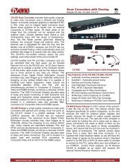
TUTORIAL SERIES FORTUTORIAL #7LEVEL 1 – 3D WIREFRAMEUSING WCS, FACING, CONTOURING, POCKETING, DRILLING,IMPORT FROM LIBRARY.
<strong>Mill</strong> <strong>Level</strong> 1 TUTORIAL 7Objectives:The Student will design a 3-dimensional wireframe drawing by:Creating a rectangle.Creating parallel lines.Creating fillet radii.Creating arcs knowing the center location and the diameter.Creating an arc tangent to three entities.Using Translate to create a 3-dimensional wireframe.The Student will create a 2-dimensional milling toolpath consisting of:First SetupFacing the bottom of the part for an even surface.Importing from the library 9/16 tap holes.Drilling 3/8 holes.Second SetupFacing the top of the partMachining simultaneous two pockets with different depths.Circle milling the 2.0“ hole.Machining a 2D contour.The Student will check the toolpath using Mastercam’s Verify module by:Defining a 3-dimensional rectangular block the size of the workpiece.Running the Verify function to machine the part on the screen.Page 7-2
<strong>Mill</strong> <strong>Level</strong> 1 TUTORIAL 7GEOMETRY CREATIONSetting up the Graphic User InterfaceBefore starting the geometry creation we should customize the toolbars to see the toolbars required tocreate the geometry and machine a 2D part. See Getting started page A-4 for details.Make sure that the Grid is enabled. It will show you where the part origin is. See Getting started page A-6 for further information.The Operations Manager to the left of the screen can be hidden to gain more space in the graphic areafor design. From the keyboard, press Alt + O keys simultaneously to hide it. Repeat this <strong>com</strong>mand tomake it visible again.Starting a new fileFileNewSTEP 1: CREATE THE OUTSIDE PROFILEStep Preview:Page 7-3
<strong>Mill</strong> <strong>Level</strong> 1 TUTORIAL 7CreateRectangular ShapesType the Width, the Height and the Radius of the fillet as shown in thefollowing picture.Select the Rectangular Shape.Select the left bottom radio button as the anchor.Select this radio buttonDo not exit the dialog box until you select the base point[Select position for the base point]: Select the center location of the grid (the origin).Select the OriginSelect the OK button to exit the rectangle dialog box.Use the Fit icon to fit the drawing to the screen.Page 7-4
<strong>Mill</strong> <strong>Level</strong> 1 TUTORIAL 7During the geometry creation of this tutorial, if you make a mistake, to undo the last step you can use theUndo icon. You can undo as many steps as needed. If you delete or undo a step by mistake, just usethe Redo icon.STEP 2: CREATE THE 9/16“ AND 3/8“ DIAMETER CIRCLES KNOWING THE CENTERPOINT AND THE DIAMETERStep Preview:2.1 Create the two 9/16 diameter circlesCreateArcCircle Center PointEnter the Diameter value9/16 (Enter).To be able to create more than one circle with the same diameter, select the diameter icontolock the value.[Enter the center point]: Select the center point of the fillet arcs as shown in the following twopictures.Select the centerof the fillet arcPage 7-5
<strong>Mill</strong> <strong>Level</strong> 1 TUTORIAL 7Select the Apply button.2.2 Create the two 3/8 diameter circlesChange the diameter to 0.375 and leave it locked (Press Enter)[Enter the center point]: Select the center point of the fillet arcs as shown in the following twopictures.Page 7-6
<strong>Mill</strong> <strong>Level</strong> 1 TUTORIAL 7Select the Apply button.to continue using the same <strong>com</strong>mand.STEP 3: CREATE THE CIRCLES WITH 3.0“AND 2.0“ DIAMETERSStep Preview:3.1 Create the 3.0 “ diameter circle.Unlock the value by reselecting the diameter icon.Enter the Diameter value3.0 (Enter).[Enter the center point]: Select the Fast Point icon.Enter the values into the box to the left of the icon: 4.0, 3.0 (Enter).Select the Apply button.to continue using the same <strong>com</strong>mand.Page 7-7
<strong>Mill</strong> <strong>Level</strong> 1 TUTORIAL 73.2 Create the 2.0“ diameter circle.Enter the Diameter value 2.0 “ (Enter).[Enter the center point]: Select the Centerlocation of the 3.0 “diameter.Select the OK button.STEP 4: CREATE THE LEFT SIDE POCKETStep Preview:4.1 Create parallel lines.Sub Step Preview:CreateLineParallelPage 7-8
<strong>Mill</strong> <strong>Level</strong> 1 TUTORIAL 7[ Select a line ]: Select Entity A.[ Select the point to place a parallel line through ]: Pick a point above the selected line.Type the Distance 1.5 (Enter).[ Select a line ]: Select Entity A.[ Select the point to place a parallel line through ]: Pick a point above the selected line.Type the Distance1.5 + 3.0 (Enter).Remember that Mastercam performsbasic math functions.Select Entity A[ Select a line ]: Select Entity B.[ Select the point to place a parallel line through ]: Pick a point to the right of the selected line.Type the Distance0.5 (Enter).Select Entity BSelect the OK button to exit the <strong>com</strong>mand.Page 7-9
<strong>Mill</strong> <strong>Level</strong> 1 TUTORIAL 74.2 Create the two polar lines using line endpoints <strong>com</strong>mand.Sub Step Preview:CreateLineEndpointsEnter the Length and the Angle:[Specify the first endpoint]: Select the Center of the 2” diameter circle.Select the centerSelect the Apply button. to createanother line using the same <strong>com</strong>mand.Enter the Length and the Angle:(Press Enter)[Specify the first endpoint]: Select the Endpoint of the line as shown.Select the OK button.Page 7-10
<strong>Mill</strong> <strong>Level</strong> 1 TUTORIAL 74.3 Remove parts of the 3.0“ diameter circle that lie above and below the polar lines usingDivideBy dividing the arc we are maintaining the part of the arc that is needed for the right side pocket.Sub Step Preview:EditTrim/BreakTrim/Break/ExtendSelect the Divide icon from the trim ribbon bar.[Select the curve to divide]: Select Entity A here.[Select the curve to divide]: Select Entity B here.Select the Entity A hereSelect the OK button.Select the Entity B here4.4 Creating the 0.125 radius fillets at all corners of the left side pocketNote that the fillet <strong>com</strong>mand will allow us to automatically trim the geometry.Sub Step Preview:Page 7-11
<strong>Mill</strong> <strong>Level</strong> 1 TUTORIAL 7CreateFilletEntitiesEnter the fillet Radius 0.125Enable the Trim icon from the Ribbon band.[Fillet: Select an entity]: Select Entity AFillet: Select another entity]: Select Entity B[Fillet: Select an entity]: Select Entity B again[Fillet: Select another entity]: Select Entity C[Fillet: Select an entity]: Select Entity C again[Fillet: Select another entity]: Select Entity D[Fillet: Select an entity]: Select Entity D again[Fillet: Select another entity]: Select Entity E[Fillet: Select an entity]: Select Entity E again[Fillet: Select another entity]: Select Entity F[Fillet: Select an entity]: Select Entity F again[Fillet: Select another entity]: Select Entity ASelect Entity BhereSelect Entity ChereSelect Entity AhereSelect Entity DhereSelect Entity FhereSelectEntity EhereSelect the OK button to exit fillet <strong>com</strong>mand.Page 7-12
<strong>Mill</strong> <strong>Level</strong> 1 TUTORIAL 7STEP 5: CREATE THE RIGHT SIDE POCKETStep Preview:5.1 Create parallel linesSub Step Preview:CreateLineParallel[ Select a line ]: Select Entity A.[ Select the point to place a parallel line through ]: Pick a point above the selected line.Type the Distance 1.0 (Enter).[ Select a line ]: Select Entity A.[ Select the point to place a parallel line through ]: Pick a point above the selected line.Type the Distance1.0 + 4.0 (Enter).Select Entity APage 7-13
<strong>Mill</strong> <strong>Level</strong> 1 TUTORIAL 7[ Select a line ]: Select Entity B.[ Select the point to place a parallel line through]: Pick a point above the selected line.Type the Distance0.5 (Enter).[ Select a line ]: Select Entity C.[ Select the point to place a parallel line through ]: Pick a point to the right of the selected line.Type the Distance7.5 (Enter)Select Entity BSelect Entity C[ Select a line ]: Select Entity D[ Select the point to place a parallel line through ]: Pick a point to the left of the selected line.Type the Distance2.25 (Enter)Select Entity D[ Select a line ]: Select Entity D again[ Select the point to place a parallel line through ]: Pick a point to the left of the selected line.Type the Distance3.0 (Enter)Select the OK button to exit the <strong>com</strong>mand.Page 7-14
<strong>Mill</strong> <strong>Level</strong> 1 TUTORIAL 75.2 Creating the 0.250 radius fillets at 3 corners of the right side pocketRemember that the fillet <strong>com</strong>mand will allow us to automatically trim the geometry.Sub Step Preview:CreateFilletEntitiesEnter the fillet Radius 0.250Make sure that the Trim icon in the Ribbon band is enabled.[Fillet: Select an entity]: Select Entity AFillet: Select another entity]: Select Entity B[Fillet: Select an entity]: Select Entity C[Fillet: Select another entity]: Select Entity D[Fillet: Select an entity]: Select Entity D again[Fillet: Select another entity]: Select Entity ESelect Entity C hereSelect Entity D hereSelect Entity B hereSelect Entity A hereSelect Entity E hereSelect the Apply button.to finish the last fillet and continue to use the same <strong>com</strong>mand.Page 7-15
<strong>Mill</strong> <strong>Level</strong> 1 TUTORIAL 75.3 Creating the 0.375 radius filletSub Step Preview:Change the fillet Radius 0.375[Fillet: Select an entity]: Select Entity A[Fillet: Select another entity]: Select Entity BSelect Entity A hereSelect Entity B hereSelect the OK button.Page 7-16
<strong>Mill</strong> <strong>Level</strong> 1 TUTORIAL 75.4 Creating an arc tangent to three entitiesSub Step Preview:CreateArcArc TangentEnable Arc Tangent 3 Entities icon in the Ribbon Bar.[Select the entity that the arc is to be tangent to]: Select Entity A[Select the entity that the arc is to be tangent to]: Select Entity B[Select the entity that the arc is to be tangent to]: Select Entity CSelect Entity A hereSelect Entity B hereSelect Entity C hereSelect the OK button.Page 7-17
<strong>Mill</strong> <strong>Level</strong> 1 TUTORIAL 75.5 Delete the construction line.Sub Step Preview:Select the line as shown to the right.Select the Delete entity icon.Select this line5.6 Trim the geometry using Trim 2 entities and Trim 3 entities optionsSub Step Preview:EditTrim/BreakTrim/Break/ExtendPage 7-18
<strong>Mill</strong> <strong>Level</strong> 1 TUTORIAL 7Select the Trim 2 entities button.[Select the entity to trim/extend]: Select Entity A.[Select the entity to trim/extend to]: Select Entity B.Select Entity A hereSelect Entity B hereSelect the Trim 3 entities button.[Select the first entity to trim/extend]: Select Entity C[Select the second entity to trim/extend]: Select Entity D[Select the entity to trim/extend to]: Select Entity ESelect Entity E hereSelect Entity C hereSelect the Repaint button.Select Entity D hereSelect the OK button.Page 7-19
<strong>Mill</strong> <strong>Level</strong> 1 TUTORIAL 7STEP 6: CREATE THE 3-D WIREFRAMEStep Preview:XformTranslate[ Select entities to translate ]: Hold-downthe Shift key and select Entity A as shown.Select Entity ANote that the entire rectangle should behighlighted. Otherwise, please check theUser Notes on how to fix geometryproblems in chainingSelect all the circlesSelect all the circles as shown.Select the End Selection button.Enable Join.Set the number of translations to # 1.Change the Delta value on Z to -1.0.Select the Apply button to continue.Page 7-20
<strong>Mill</strong> <strong>Level</strong> 1 TUTORIAL 7[ Select entities to translate ]: Hold-down the Shift key and select Entity B.Note that the entire pocket should behighlighted.Select Entity BSelect the End Selection button.Enable Join.Set the number of translations to # 1.Change the Delta value on Z to -0.375.Select the Apply button to continue.Page 7-21
<strong>Mill</strong> <strong>Level</strong> 1 TUTORIAL 7[ Select entities to translate ]: Hold-down the Shift key and select Entity C.Note that the entire pocket should be highlighted.Select Entity CSelect the End Selection button.Change the Delta value on Z to -0.750.Select the OK button to exit.ScreenClear colorsSelect the Isometric View from the view toolbar to see the stock.Select Fit button.Page 7-22
<strong>Mill</strong> <strong>Level</strong> 1 TUTORIAL 7The final geometry should look as shown belowSTEP 7: SAVE THE FILEFileSave asFile name: “Your Name_7”Select the OK button.Page 7-23
<strong>Mill</strong> <strong>Level</strong> 1 TUTORIAL 7TOOLPATH CREATIONSUGGESTED FIXTURE FOR SETUP 1:ZYXSETUP SHEET FOR SETUP 1:Page 7-24
<strong>Mill</strong> <strong>Level</strong> 1 TUTORIAL 7STEP 8: SELECT THE MACHINE AND SET UP THE STOCK TO BE MACHINEDTo display the Operations Manager press Alt + O.Use the Fit icon to fit the drawing to the screen.Machine type<strong>Mill</strong>DefaultIf a machine is already selected in the Toolpaths Manager, skip the machine selection step.Select the plus in front of Properties to expand the ToolpathsGroup Properties.Select the plusSelect Tool settingsSelect Tool Settings to set the tool parametersChange the parameters to match the screenshot below.Page 7-25
<strong>Mill</strong> <strong>Level</strong> 1 TUTORIAL 7Select Stock Setup tab.Make sure that the Shape is set to Rectangular.Select the Bounding box button for the system to automatically find the part’s overall dimensions.Enable Lines Arcs to create the geometry of the stockExpand X, Y and Z values with 0.1Select the OK button to exit the Bounding Box window.Page 7-26
<strong>Mill</strong> <strong>Level</strong> 1 TUTORIAL 7Select the OK button to exit Machine Group Properties.Select the Isometric View from the view toolbar to see the stock.Select Fit button.The stock should look as shown below.Page 7-27
<strong>Mill</strong> <strong>Level</strong> 1 TUTORIAL 7STEP 9: USING WCS MANAGER FLIP THE PART. MACHINE THE BOTTOM OF THEPART FOR AN EVEN SURFACE FOR FUTURE OPERATIONSUse the View Manager as a central point for selecting, editing, creating and managing views. You canselect which views to use for the Cplane, Tplane, or the work coordinate system (WCS). You can also seta new origin of a view and assign a new work offset (G54, G55...)to a view9.1 Using WCS (Work Coordinate System) to define the new viewStep Preview:Select WCS in the Status Bar.Select View Manager.Select Geometry button.You can define a new view based on existinggeometry like 2 lines, a flat entity (circle or flatsurface) or 3 points.Page 7-28
<strong>Mill</strong> <strong>Level</strong> 1 TUTORIAL 7Select the lines as shown below.Note that the first line that you select will determine the X axis orientation of the future view, and thesecond line will determine Y axis. Z axis should always be orientated towards the outside of the part.Select the first lineSelect the second lineSelect the OK button to accept the view.XYZEnter the New View Name: “Bottom Part View”Make sure that Associative and Set new origin are enabled.Page 7-29
<strong>Mill</strong> <strong>Level</strong> 1 TUTORIAL 79.2 Using WCS to set a new origin for the viewClick on Select button to select the new Origin from the graphic area.[Select a point]: Select Endpoint A as ashown.Select Endpoint A9.3 Using WCS to set the new view as the current tool plane, construction plane and WCSSelect Bottom Part View and click on the Set your current WCS, construction plane and tool planewith their origins to the selected view button.Change the Z value in the Origin field to 1.0 to set Program zero at the finish size not at the top ofthe stock.Page 7-30
<strong>Mill</strong> <strong>Level</strong> 1 TUTORIAL 7Select the OK button to exit.Select the Isometric view.Select Fit button.The part should look as shown below.The origin for the new planeSTEP 10: FACING THE BOTTOM OF THE PART TO CREATE AN EVEN SURFACE FORFUTURE OPERATIONSFacing toolpath is used to quickly clean the stock from the top of a part, and create an even surface forfuture operations. You can base the toolpath on either chained geometry or on the current stock model.Toolpath Preview:Page 7-31
<strong>Mill</strong> <strong>Level</strong> 1 TUTORIAL 710.1 Selection of the top of the partToolpathsFaceSelect the OK button to accept the NC file name.[ Select OK to use defined stock or select chain1 ]: Select the OK button touse defined stock.Note that in the Toolpath Type the Facing icon is selected.10.2 Selecting the 3.0 “ diameter Face millFrom the Tree view list, select Tool.Click on Select library tool.Select the Filter button and make the changes as shown below.Page 7-32
<strong>Mill</strong> <strong>Level</strong> 1 TUTORIAL 7Select the OK button.Highlight the 3.0“ Face mill in the Tool Selection window.Select the OK button.10.3 Set the Tool parametersChange the parameters in the Tool page as shown.Note that the Feed rate, Plunge rate, Retract rate and Spindle speed are based on the tooldefinition. Change them as needed.Page 7-33
<strong>Mill</strong> <strong>Level</strong> 1 TUTORIAL 710.4 Set the Cut Parameters pageFrom the Tree view list, select Cut Parameters and change the parameters as shown.Cutting method set to Zigzag for back and forth motion.Across overlap sets the overlap amount for the edges of the stock perpendicular to the cutdirection.Along overlap sets the overlap amount for the edges of the stock parallel to the cut direction.Approach/Exit distance sets an additional distance away from the stock on the first/last pass.Maximum stepover set the distance between adjacent passes in the toolpaths.Even number of passes (available only with Zigzag cutting method) sets an even number passeswhich ensures that the last pass reverses the cutting direction. Thid strategy prevents burring orchipping on the last pass.Roughing angle set to 0 will make the first pass along positive X axis.Move between cuts set to High speed loops creates 180 degrees arcs between each cut.Page 7-34
<strong>Mill</strong> <strong>Level</strong> 1 TUTORIAL 710.5 Set the Linking Parameters pageFrom the Tree view list, select Linking Parameters and change the parameters as shown.Note that the Depth is set to absolute and 0 and the Top of stock is set to 0.1. This is the result of settingup Z0 to the top of the finish size while defining the Bottom View.Press Alt+ T to remove the toolpath display.Page 7-35
<strong>Mill</strong> <strong>Level</strong> 1 TUTORIAL 7STEP 11: IMPORT THE OPERATIONS FOR THE 9/16 TAP HOLES FROM THELIBRARYToolpath Preview:11.1 Import the operationsRight-mouse click in Toolpaths Manager window.Select Import…Select the drop-down arrow in the Source folder and select the Your name. Operations.Page 7-36
<strong>Mill</strong> <strong>Level</strong> 1 TUTORIAL 7Click on the 9/16-12 Tap group to select all threeoperations.Make sure that Assign current system tool and constructionplanes is enabled. This option adjusts the imported operationsto use the current tool plane and construction plane.Select the OK button.Select the No button to import the operation group.Select the OK button.Close the Import Toolpath Operations dialog box.Note that all the imported operations have no geometry. We are going to add the center points andregenerate the toolpaths as shown in the following steps.11.2 Add the center points in the toolpath geometrySelect the first drill operation, Geometry.Select GeometrySelect the OK button.Page 7-37
<strong>Mill</strong> <strong>Level</strong> 1 TUTORIAL 7Right–mouse click and Select Add points…Select the Entities button in the Drill Point Selection.[Select entities]: Select the 9/16 “ diameter circles as shown.Select the 9/16diameter circlesSelect the OK button twice to exit Drill Point Manager.Page 7-38
<strong>Mill</strong> <strong>Level</strong> 1 TUTORIAL 7Select the Regenerate all selected operations icon for the changeto be applied.Select Alt +T keys to remove the toolpath displayHolding the right-mouse button, drag the new Geometry (2) Points on top of Peck drill Geometry.Release and select Add.Right-mouse clickon Geometry, holddown and dragSelect No button, otherwise the holes will be drilled at the samedepth as the depth of the spot drilling operation.11.3 Modify the drill parametersSelect Parameters in the Peck Drill operation.Select the Peck Drill Parameters in the Toolpaths Manager.Select the ParametersFrom the Tree view list, select Tool and change the Comment to “Drilling all 31/64 diameterholes.”Page 7-39
<strong>Mill</strong> <strong>Level</strong> 1 TUTORIAL 7From the Tree view list, select Linking Parameters and change the Depth as shown in the pictureto the right.From the extanded Tree view list,select the Tip <strong>com</strong>p and change the breakthrough amount valueas shown.Breakthrough amount value allows you to give an extra amount for the tool to godeeper than the final depth to prevent any remaining material for the cut-outs.Tip length value is automatically calculated by the system based on the diameter and tipangle of the tool. The value is added to the final depth.Select the OK button to exit drilling parameters.Page 7-40
<strong>Mill</strong> <strong>Level</strong> 1 TUTORIAL 7Copy the geometry in the tapping toolpath following the same steps shown for drillinggeometry.Select the Regenerate all dirty operations icon.Press Alt+ T to remove the toolpath display.STEP 12: DRILLING THE 3/8“ DIAMETER HOLESToolpath Preview:12.1 Drill points selectionToolpathsDrillSelect the Entities button.[Select entities]: Select the 3/8“ diameter circles.Select the 3/8diameter circlesSelect the OK button to exitDrill Point Selection.Page 7-41
<strong>Mill</strong> <strong>Level</strong> 1 TUTORIAL 712.2 Set the Tool parametersFrom the Tree view list, select Tool.Click on Select library tool.Using Filter select the 3/8“ Drill as shown in the previous steps.Add the <strong>com</strong>ment as shown below.12.3 Set the Cut ParametersFrom the Tree view list, select the Cut Parameters page and change the Cycle to Peck Drill asshown.Page 7-42
<strong>Mill</strong> <strong>Level</strong> 1 TUTORIAL 712.4 Set the Linking ParametersFrom the Tree view list, select the Linking Parameters page and change the Depth as shown.From the extanded Tree view list, select the Tip <strong>com</strong>p, enable it and add a Breakthrough amountas shown to ensure the <strong>com</strong>plete machining of the through holes.Select the OK button to exit 2D Toolpaths – Drill parameter pages.Page 7-43
<strong>Mill</strong> <strong>Level</strong> 1 TUTORIAL 7STEP 13: SPOT DRILL THE 3/8“ DIAMETER HOLESNote that we have not yet spot drill the 3/8” diameter holes. In this step we will have to add the centerpoints of the 3/8 diameter holes in the existing spot drilling operation geometry. We will also change thedepth of the spot drill for the 3/8 diameter holes only.Toolpath Preview:13.1 Add the center points of the 3/8” diameter holes in the existing spot drilling operationIn the Toolpaths Operations Manager, Right mouse click on the last Peck drill operation Geometryhold and drag the geometry above the Drill/Conterbore Geometry.Release the mouse and select Add from the list.Right mouse click hold and dragSelect No button to do not retain the depth from the 3/8 drilling operation.Page 7-44
<strong>Mill</strong> <strong>Level</strong> 1 TUTORIAL 713.2 Modify the depth of spot drilling for the 3/8 holesSelect the Geometry of the spot drilling operation.Select GeometryClick on the third Point and make sure that one of the 3/8 holes is selected.Then, Right–mouse click on the third point and select Change at point…In the Drill change at point dialog box, enable Depth and changethe value to -0.23.Select the OK button to exit Drill change at point dialog box.Repeat the steps for the fourth point and change the depth to -0.23.Select the OK button to exit Drill Point Manager dialog box.Regenerate the toolpath.Page 7-45
<strong>Mill</strong> <strong>Level</strong> 1 TUTORIAL 7STEP 14: BACKPLOT THE TOOLPATHSBackplotting shows the path the tools take to cut the part. This display lets you spot errors in theprogram before you machine the part. As you backplot toolpaths, Mastercam displays the current X, Y,and Z coordinates in the lower left corner of the screen.Click on the Toolpath Group in the Toolpaths Manager to select alloperations.Select Toolpath Group 1Select the Backplot selected operations button.Make sure that you have the following buttons turned on (theywill appear pushed down).Display Toolsand Rapid movesSelect the Isometric View from the view toolbar to see the stock.Select the Fit button.You can adjust the speed of the backplot.You can step through the Backplot by using the Step forward or Step back buttons.Page 7-46
<strong>Mill</strong> <strong>Level</strong> 1 TUTORIAL 7Select the Play button in the VCR bar.Select the OK button to exit Backplot.STEP 15: VERIFY THE TOOLPATHSVerify simulates the machining of a part from a stock model display. The stock dimensions are based onthe values that we specified in the Stock Setup.Select all operations button.Select the Verify selected operations button.Page 7-47
<strong>Mill</strong> <strong>Level</strong> 1 TUTORIAL 7Simulate tool simulates the toolpaths, displaying thesolid tool without the holderUpdate after each toolpath updates the stock after eachoperation.Stop on collision pauses the verification when the tooltouches the part with a rapid move.Select the Configure button.Page 7-48
<strong>Mill</strong> <strong>Level</strong> 1 TUTORIAL 7Initial stock size source shouldbe set to Stock Setup to use thestock information from StockSetup.Use True Solid allows you, afterverifying the part, to rotate andmagnify the part to more closelycheck features, surface finish, orscallops.Cutter <strong>com</strong>p in control allowsVerify to use the informationregarding the tool diameter andto simulate the cutter<strong>com</strong>pensation.Change tool/color to change thecolor of the cut stock toindicated tool changes in thetoolpath.Select the OK button to exit Verify Options.Set the Verify speed by moving the slider bar in the speed control bar.Select the Play button to start simulation.The finished part should appear as shown in the following picture.Select the OK button to exit Verify.Page 7-49
<strong>Mill</strong> <strong>Level</strong> 1 TUTORIAL 7SUGGESTED FIXTURE FOR SETUP 2:The stock is held on afixture plate using thetapped and the drillholes. The two 9/16“bolts and two 3/8“dowels hold and positonthe part.SETUP SHEET FOR SETUP 2:Page 7-50
<strong>Mill</strong> <strong>Level</strong> 1 TUTORIAL 7STEP 16: CREATING AND RENAMING TOOLPATH GROUPS; RENAMING THE NCFILETo machine the part in two different setups, we will need to have two separate programs. To be able topost process separately the operations of each setup, we will create them under different toolpathgroups with different NC names.Step Preview:16.1 Rename the current Toolpath Group-1 and the NC fileClick two times on the Toolpath Group -1 to highlight it and rename itMachine Part Bottom.Right-mouse click on the toolpath group and select Edit selected operations and then, selectChange NC file name.Enter the new NC name: “Machine Part Bottom”.Select the OK button.Page 7-51
<strong>Mill</strong> <strong>Level</strong> 1 TUTORIAL 716.2 Create a new Toolpath GroupRight-mouse click on the Machine Group-1Select Groups from the drop down list and then select NewToolpath group.Rename the toolpath group: “Machine Part Top”.Make sure that the red insert arrow is below the Machining Part Top group;otherwise click on it and drag it below. This ensures that the next operationwill be added in the proper group.STEP 17: SET THE TOP VIEW AS THE CURRENT WCS, TOOL AND CONSTRUCTIONPLANEToolpath Preview:17.1 Using WCS to set the Top view as the current tool plane, construction plane and WCSSelect WCS in the Status Bar.Select WCS Manager.Page 7-52
<strong>Mill</strong> <strong>Level</strong> 1 TUTORIAL 7Select Top View and click on the Set your current WCS, construction plane and tool plane withtheir origins to the selected view button.Select the OK button.Select the Isometric view.Select Fit button.The part should look as shown to theright.Note that the origin is set at top of thepart at the lower left corner. Follow nextsub step if you want to move the originat the upper left corner.17.2 Using WCS to set the origin at the upper left cornerSelect WCS in the Status Bar.Select View Manager.Page 7-53
<strong>Mill</strong> <strong>Level</strong> 1 TUTORIAL 7Click on the Select button in the Origin area as shown.[Select a point]: Select Endpoint A.Select Endpoint AChange the Z value in the Origin area to 0 to set again the part zero at the finish size.The new origin coordinates should look as shown.Select the OK button to exit View Manger.Note that the grid moves at the upper left corner at the top of the part at the finished size.Page 7-54
<strong>Mill</strong> <strong>Level</strong> 1 TUTORIAL 7STEP 18: FACING THE TOP OF THE PARTStep Preview:18.1 Copy the Facing operation in the Machine Part Top groupRight-mouse click on the existing Facing operation and select Copyfrom the list.Right-mouse click below Machine Part Top group and select Paste from the list.Page 7-55
<strong>Mill</strong> <strong>Level</strong> 1 TUTORIAL 718.2 Change the planes to Top in the Facing operationFrom the Toolpaths Operations Manager select Parameters in the new Facing operation.From the Tree view list select Planes.Click on Select WCS view button as shown.From View Selection dialog box, select the Top view as shown.Select the OK button to exit View Selection dialog box.Select Copy to tool plane and Copy to construction plane buttons to set all the planes to the Topplane.Page 7-56
<strong>Mill</strong> <strong>Level</strong> 1 TUTORIAL 7From the Tree view list, select the Tool page and change the <strong>com</strong>ment as shown.Select the OK button to exit.Press Alt+ T to remove the toolpath display if needed.STEP 19: ROUGH MACHINING THE TWO POCKETS IN THE TOP VIEWStep Preview:Page 7-57
<strong>Mill</strong> <strong>Level</strong> 1 TUTORIAL 719.1 Select the bottom chains of the two pocketsTo be able to machine both pockets in the same operation, although they each have different depths, weneed the 3D wireframe to select the pockets at the bottom.ToolpathsPocketEnabled C-plane in Chaining to be able to select the chains without stopping at the branches.Select the two pockets at the bottom, as shown.Select the firstpocket hereNote that both pockets are highlighted.Select thesecond pocketSelect the OK button to exit Chaining.Page 7-58
<strong>Mill</strong> <strong>Level</strong> 1 TUTORIAL 719.2 Select the 1.0 “ Flat end mill and set the parameters in the Tool pageFrom the Tree view list, select Tool.Select the 1.0 “Flat end mill using the Filter options as shown in the facing operation.Make the necessary changes to match the parameters with the screenshot below.Remember that the Feed rate. Plunge rate, Retract rate and Spindle speed values are all define in theparameters of the tool definition. Change them as needed.Page 7-59
<strong>Mill</strong> <strong>Level</strong> 1 TUTORIAL 719.3 Set the Cut ParametersFrom the Tree view list, select the Cut Parameters page and change the parameters as shown.Pocket type set to Standard can be used only with closed chains. The tool will be constrainedinside of the closed chain.Machining Direction set to Climb cuts in one direction with the tool rotating in the oppositedirection of the tool motion. See the graphic below.Tip Comp set to the Tip sets the tool offset to the tool tip.Roll cutter around corners inserts arc moves around the corners in the toolpath for a smothertool movement. Set to Sharp (135 degrees or less) will roll the tool at the sharp corners.Page 7-60
<strong>Mill</strong> <strong>Level</strong> 1 TUTORIAL 7From the extended Tree view list, select Roughing and select as cutting method Constant OverlapSpiral.Stepover percentage sets the distance between roughing passes in the XY axis as apercentage of the tool diameter and will automatically update the stepover distance.Minimize tool burial clears the area around pocket islands (semi islands in our case) toavoid tool damage due to removing too much stock at once.Spiral inside to outside enabled allows you to spiral from the center to the pocket wall.Display stock for constant overlap spiral previews the amount of stock removed by theroughing passes.Tolerance for remachining and constant overlap spiral determines the accuracy of thetoolpath when using one of the two options. Re<strong>com</strong>mended tolerance is the default.Select the plus sign in front of the Roughing to expand the Tree view list, andselect Entry Motion (if needed).Enable Ramp options and change the parameters to match the following screenshot.The ramp length value will be determined by Mastercamand can not be smaller then the Minimum length or biggerthen the Maximum length.Z clearance sets the height above the stock where theentry ramp will start.XY clearance sets the minimum distance in the XY planebetween the ramp and the pocket wall.Plunge zig/zag angles set the ramp angles as the tool zigzagsto the bottom of the pocket before beginning thecutting pass.Auto angle sets automatically the angle in the XY planebased on the longest area of the pocket.Additional slot width adds a fillet at the end of each rampfor a smoother tool movement.Page 7-61
<strong>Mill</strong> <strong>Level</strong> 1 TUTORIAL 7Select Finishing and disable the option as with this operation we want to rough only the part.From the Tree view list, select Depth Cuts and enable the option.Depth cuts are the Z axis cuts that the tool makes in a pocket toolpath.Max rough step sets the maximum amount that can be machined in one step.By pocket enable the system to <strong>com</strong>plete all depth cuts in the first pocket before movingto next one.Mastercam never performs unequal depth cuts. For example, in our case, the left side pocket is 0.375deep; the step is calculated: (0.375-0.02)/2 = 0.1775 which is smaller then 0.3. The same way the systemcalculates the step for the second pocket; (0.75-0.02)/3 =0.2433Page 7-62
<strong>Mill</strong> <strong>Level</strong> 1 TUTORIAL 719.4 Set the Linking ParametersFrom the Tree view list, select Linking Parameters and enable Clearance height and set the Top[ ofthe stock and the final Depth as shown.Depth value sets the final machining depth for the pocket operation. The value is set to 0 andincremental and is measured from the two geometry chains that we selected. This insures thatboth of them are going to be machined to the appropriate depth.Choosing Incremental tells the system to calculate the value relative to either the current topof stock (as with Clearance parameter), relative to the selected geometry (as with Top of stockand Depth parameters), or relative to the depth of each cut (as with Feed plane and Retract ).Select the OK button to exit 2D Toolpaths Pocket parameters.Press Alt+ T to remove the toolpath display.Page 7-63
<strong>Mill</strong> <strong>Level</strong> 1 TUTORIAL 7STEP 20: FINISHING THE TWO POCKETSToolpath Preview:20.1 Copy the existing pocket operationYou can copy an operation when machining the same geometry and using the same type of toolpath.Advantages of using a copy of an existing operation is that we do not need to select the geometry chainsand we can use some of the parameters set up in the original operation.Right-mouse click and hold it down on the folder icon in front of the Pocket toolpath.Drag the mouse down and release it.Select Copy after.You should now have two pocket toolpaths.Left-click on the second pocket Parameters.Select ParametersPage 7-64
<strong>Mill</strong> <strong>Level</strong> 1 TUTORIAL 720.2 Select the 0.75“ Flat end mill and set the Tool page parametersFrom the Tree view list, select the Tool page.Click on Select library tool.Following the steps outlined earlier, using the Filter option, select the ¾ “ Flat End <strong>Mill</strong>.20.3 Set the Cut ParametersFrom the Tree view list, select the Cut Parameters and remove the stock to leave on the walls andon the floors.Page 7-65
<strong>Mill</strong> <strong>Level</strong> 1 TUTORIAL 7From the Tree view list, select Entry Motion and disable the entry asshown.From the Tree view list, select Finishing and enable the Finish to finish the walls. Set the rest ofparameters to match the following screenshot.Passes sets the number of finish passes.Spacing sets the amount of stock to be removed with each cut. Because we set thenumber of passes to 1, the amount of stock to be remove is the stock to leave on thewalls amount set in the roughing operation.Finish outer boundary needs to be enabled to finish the walls of the pocket.From the Tree view list, select the plus sign in front of the Finishing and set the parameters for theLead In/Out as shown tomake smooth entry/exittool moves in and out ofthe remaining stock.Page 7-66
<strong>Mill</strong> <strong>Level</strong> 1 TUTORIAL 7From the Tree view list, select Depth Cuts and disable the option to remove the remaining stock inone step at the final depth.Select the OK button to exit the 2D Toolpaths- Pocket.Press Alt+ T to remove the toolpath display.Regenerate the toolpath.STEP 21: BACKPLOT THE POCKET TOOLPATHSIn the Toolpaths Operations Manager, click on the first pocket operation.Holding down the Shift key select the second pocket.Click on Backplot selected operations icon.Make sure that you have the following buttons turned on (they will appear pushed down).Display toolDisplay rapid movesQuick verifySelect the Top View from the view toolbar to see the stock.Select the Fit button.Select the Play button in the VCR bar.Page 7-67
<strong>Mill</strong> <strong>Level</strong> 1 TUTORIAL 7You can adjust the speed of the backplot.Note the remaining material in the corners. The ¾“ Flat End <strong>Mill</strong> can not clean up the stock. In the nextoperation we will remachine the corners using a smaller tool.Select the OK button to exit Backplot.STEP 22: REMACHINING THE TWO POCKETSNote that the 3/4” Flat End <strong>Mill</strong> could not clean the 0.125” radius fillets. Using the 1/8” Flat End <strong>Mill</strong> toremove all the material inside the pocket will not be efficient. We will remove the remaining material onlyby using a 1/8” Flat End <strong>Mill</strong> tool with the remachining pocket style.Toolpath Preview:22.1 Copy the existing last pocket operationYou can copy an operation only when machining the same geometry using the same toolpath. Advantagesof using a copy of an existing operation is that we don’t need to select the geometry chains and we canuse some of the parameters set up in the original operation.Page 7-68
<strong>Mill</strong> <strong>Level</strong> 1 TUTORIAL 7Select only the second Pocket (operation 8).Right-mouse click and hold it down on the folder icon in front of the second Pocket toolpath.Drag the mouse down and release it.Select Copy after.You should now have three pocket toolpaths.Left-click on the last pocket Parameters.Select Parameters22.2 Select the 1/8“ Flat end mill and set the Tool parametersFrom the Tree view list, select the Tool page.Click on Select library tool.Following the steps outlined earlier, using the Filter option, select the 1/8” Flat End <strong>Mill</strong>.Page 7-69
<strong>Mill</strong> <strong>Level</strong> 1 TUTORIAL 722.3 Set the Cut ParametersSelect Cut Parameters and change the Pocket type to Remachining as shown below.Set the Compute remaining stock from the Roughing tool diameter and set the parameters asshown.Compute remaining stock from:Roughing tool diameter enables the system to calculate the remaining stock for remachiningbased on the size of the tool diameter that you enter.Clearance, set as a percentage of the tool diameter, allows you to expand the remachining areaat the beginning and at the end to prevent a cusp of material remaining.Apply entry/exit curves to rough passes allows you to use the Lead in/out parameters.Machine <strong>com</strong>plete finish passes allows you to finish the entire part.From the Tree view list, select Roughing and change the Stepover percentage to 70 % to ensure a<strong>com</strong>plete removal of the stock.Page 7-70
<strong>Mill</strong> <strong>Level</strong> 1 TUTORIAL 7From the Tree view list, select Depth Cuts and enable it.Change the Max rough step as shown to remove less then ½“ of the tool diameters in one step.Select the OK button to exit from the 2D Toolpaths - Pocket.Regenerate the toolpath.Press Alt + T to remove the toolpath display.STEP 23: CIRCLE MILL THE 2.0“ DIAMETER HOLEToolpath Preview:23.1 Select the toolpath geometryFrom the Toolpaths Operations Manager, select Move insert arrow downone item until the insert arrow is bellow the last operation.Page 7-71
<strong>Mill</strong> <strong>Level</strong> 1 TUTORIAL 7ToolpathsCircle PathsCircmillFrom the Drill Point Selection, select Entities button.Select the bottom of 2.0“ diameter hole.[Select entities]: Select the circle as shown.Select the circle hereSelect the OK button to exit Drill Point Selection dialog box.Note that in the Toolpath Type theCircle <strong>Mill</strong> icon is automatically selected.23.2 Set the Tool parametersFrom the Tree view list, select the Tool page.Select the existing ¾“ Flat Endmill from the tool list window as shown.Page 7-72
<strong>Mill</strong> <strong>Level</strong> 1 TUTORIAL 723.3 Set the Cut ParametersFrom the Tree view list, select the Cut Parameters and change the parameters as shown.Compensation type set to Computer allows Mastercam to <strong>com</strong>pensate the toolpath basedon the tool diameter and does not output G41/G42 in the code.Compensation direction set to Left <strong>com</strong>pensates the toolpath to the left of the chain in theCCW direction.Tip Comp set to the Tip sets the tool offset to the tool tip.Entry/exit arc sweep set to 90 degrees makes a line between the plunge point and theentry/exit arc movement of a ¼ of a circle, at each entry/exit. See the picture below.Overlap sets how far the tool goes past the end of the toolpath before exiting. This ensures aclean finish.Entry/exit arc sweep set to 90 degreesPage 7-73
<strong>Mill</strong> <strong>Level</strong> 1 TUTORIAL 7From the Tree view list, select Roughing to add roughing passes to <strong>com</strong>pleted machine the inside ofthe hole.Enable Roughing and set the parameters as shown.Circle mill roughing creates roughing passes using tangent arcs. The result provides asmooth motion for the tool, a short NC program, and good cleanout.Stepover is set as a percentage of the tool diameter.Helical entry parameters create the roughing motion tangent to a helical entry.Output arc moves generates arc movements instead of small linear moves which make theprogram smaller.From the Tree view list, select Depth Cuts and set the parameters as shown.Depth cuts set the cuts along the Z-axis. Mastercam divides the total depth into equalsteps based on the Max rough step value.Keep tool down enabled doesn’t allow the tool to retract between cuts.Page 7-74
<strong>Mill</strong> <strong>Level</strong> 1 TUTORIAL 7From the Tree view list, select Break Through to cut <strong>com</strong>pletely through the material by theamount specified.23.4 Set the Linking ParametersFrom the Tree view list, select the Linking Parameters and change the parameters as shown.Note that the Depth is set to Incremental and 0 because we select the circle mill geometry at the bottom(final depth). Setting the Depth to Absolute and -1.0 will give the same result.Select the OK button from the 2D Toolpath – Circle <strong>Mill</strong> parameter screen.Press Alt + T to remove the toolpath display.Page 7-75
<strong>Mill</strong> <strong>Level</strong> 1 TUTORIAL 7STEP 24: CONTOUR THE OUTSIDE PROFILEToolpath Preview:24.1 Select the toolpath geometryToolpathsContourMake sure that C-plane is selected in the Chaining dialog box.Select the contour at the bottom.Select the first entity in the contour, as shown.Be sure to chain the contour in a CW direction. Otherwise select the Reversebutton.Select the contourhereSelect the OK button to exit Chaining.Page 7-76
<strong>Mill</strong> <strong>Level</strong> 1 TUTORIAL 724.2 Select the 1.0 “ diameter Flat End <strong>Mill</strong> and set the parameters in the Tool pageFrom the Tree view list, select the Tool.Select the existing 1” Flat End <strong>Mill</strong> and make all the necessary changes in the Tool page.24.3 Set the Cut ParametersSelect the Cut Parameters from the Tree view list and change the Compensation type to Control.Make sure that the parameters match the screenshot below.Cutter <strong>com</strong>pensation set in Control outputs G41 or G42 codes to turn the<strong>com</strong>pensation on. The <strong>com</strong>pensation amount or tool wear adjustment is set at thecontrol. Using this method you are programming the part edge.Page 7-77
<strong>Mill</strong> <strong>Level</strong> 1 TUTORIAL 7From the Tree view list, select Depth Cuts.Enable Depth cuts and set the Max rough step to 0.5From the Tree view list, select Lead In/Out.Note that Cutter <strong>com</strong>pensation in control requires the Lead in/out parameter to be turned on; most ofthe CNC machines need a linear move at the beginning of the program to <strong>com</strong>pensate the cutterdiameter. If you use the arc option too, make sure that the radius is larger than the radius of the tool.Entry/exit at midpoint in closed contours will move the start of the contour toolpath at themidpoint of the line that we selected when chaining.Line /Tangent will be tangent to the arc and machined first in the entry <strong>com</strong>bination. Whenexiting the part the arc will be machined first. See the graphic below.Page 7-78
<strong>Mill</strong> <strong>Level</strong> 1 TUTORIAL 7From the Tree view list, select the Break Through and enter a Break through amount to<strong>com</strong>pletely machine the profile.24.4 Set the Linking ParametersSelect the Linking Parameters and make the changes as shown.Note that the final Depth can be set to Incremental and0 due to the fact that we select as the contourgeometry the bottom of the contour.Select the OK button to exit 2D Toolpaths – Contour parameters.Page 7-79
<strong>Mill</strong> <strong>Level</strong> 1 TUTORIAL 7STEP 25: BACKPLOT THE TOOLPATHSFrom Toolpaths Operations Manager click on the Machine Part Top to select all the operationsdone in the second setup.Repeat STEP 13 to be sure that the changes have taken place.Disable the Quick verify button.Page 7-80
<strong>Mill</strong> <strong>Level</strong> 1 TUTORIAL 7STEP 26: VERIFY THE CHANGED PARTSelect the Select all operations button from Toolpath Manager if needed.Repeat STEP 15 to be sure that the changes have taken place.The finished part should appear as shown in the following picture.STEP 27: POST THE FILESRight-mouse click on the Machine Part Top group and select Edit selected operations and then,select Change NC file name.Page 7-81
<strong>Mill</strong> <strong>Level</strong> 1 TUTORIAL 7Enter the new NC name: Machine Part TopSelect the OK button.Post processing, or posting, refers to the process by which the toolpaths in the Mastercam part files areconverted to a format that can be understood by the machine tool's control (for example, G-codes).Generally, every machine tool or control will require its own post processor, customized to producecode formatted to meet its exact requirements.Make sure that all operations are selected, otherwise, Select all operations.Select the Post selected operations button from ToolpathManager.In the Post processing window, make all the necessary changes asshown to the right.NC file enabled allows you to keep the NC file and toassign the same name as the MCX file.Edit enabled allows you to automatically launch thedefault editor.Select the OK button to continue.Select the OK button to post the first group as the geometryname (“Machine Part Bottom”).Page 7-82
<strong>Mill</strong> <strong>Level</strong> 1 TUTORIAL 7Select the red X to closethe first program.Select the OK button to start the second program (“Machine Part Top”).Select the red X to closethe editor.STEP 28: SAVE THE UPDATED MCX FILESelect the Save icon.Page 7-83
<strong>Mill</strong> <strong>Level</strong> 1 TUTORIAL 7REVIEW EXERCISESStudent practice: Create the Toolpath for Exercise 1-Tutorial 7 as per the instructions below;Tips:Create the 3D geometry using Xform/Translate.Create each pocket with a different depth.Stock size use Bounding box to establish X, Y & z sizes andgive extend X, Y, and Z 0.2Face the top of the part using 3“ Face <strong>Mill</strong> (create a new tool or get it from the library)Spot Drill the 3/8“ diameter holes using 1/2“ Spot DrillDrill the 3/8“ diameter holes using 5/16“ DrillTap the 3/8“ diameter holes using 3/8 -16“ TapDrill the 1/2“ diameter holes using 1/2“ DrillAdd the ½ holes center points in the Spot Drill and edit the depth of the holes.(SeeTutorial 3)Rough Pocket the part using 1“ Flat End <strong>Mill</strong>Select each pocket at the bottomDepth = 0 (incr)Max rough step (depth cuts) = 0.25Stock to leave XY = 0.05Use Parallel spiral clean corners cutting methodRemachining Pocket the part using 1/8“ Flat End <strong>Mill</strong>Contour the part using 1.5“ Flat End <strong>Mill</strong>2 depth cuts1 rough pass; spacing = 0.11 finish pass; spacing = 0.05Backplot and Verify the toolpaths.Post process the file.Page 7-84
<strong>Mill</strong> <strong>Level</strong> 1 TUTORIAL 7Student practice: Create the Toolpath for Exercise 2-Tutorial 7as per the instructions below;Tips:Create the 3D geometry using Xform/Translate.Create each pocket with a different depth.Stock size use Bounding box to establish X &Y sizes andgive Z = 1.2“ and the stock origin Z =0.2Face the top of the part using 3“ Face <strong>Mill</strong> (create a new tool or get it from Big tools library)Center Drill the 3/8“ diameter holes using 1/4“ Center DrillDrill the 3/8“ diameter holes using 3/8“ DrillContour the part using 1.5“ Flat End <strong>Mill</strong>2 depth cutsRough Pocket the part using 1“ Flat End <strong>Mill</strong>Select each pocket at the bottomDepth = 0 (incr)Max rough step (depth cuts) = 0.25Stock to leave XY = 0.05Use Parallel spiral cutting methodRemachining Pocket the part using 3/8“ Flat End <strong>Mill</strong>Finish Pocket the part using 3/8“ Flat End <strong>Mill</strong>Backplot and Verify the toolpaths.Post process the file.Page 7-85
<strong>Mill</strong> <strong>Level</strong> 1 TUTORIAL 7NOTES:Page 7-86
<strong>Mill</strong> <strong>Level</strong> 1 TUTORIAL 7TUTORIAL 7 QUIZWhat <strong>com</strong>mand and what options were enabled to create the 3D wireframe?What does WCS stand for?What entities can be selected to define a new plane, using the Geometry option in the ViewManager?What is facing toolpath used for?What would you require as toolpath geometry, and how would you set the final Depth value whenmachining pockets with different depths in the same operation?How does the system calculate the stock for remachining when “Compute remaining stock fromRoughing tool diameter” is enabled?How is the tip length of the drill calculated in the drilling operation?Page 7-87