Compact ball nut heralding in the
Compact ball nut heralding in the
Compact ball nut heralding in the

You also want an ePaper? Increase the reach of your titles
YUMPU automatically turns print PDFs into web optimized ePapers that Google loves.
• Ball Screws
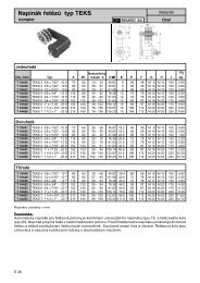
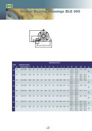
2. Recommendation of Screw Shaft End Configuration2.1 Drive side shaft end and opposite end: P2.2 Drive side shaft end and opposite end: RScrew shaftDiameter d12152025324050Unit: mmScrew shaftTap holeDiameter d Size M Depth H12 M3×0.5 915 M4×0.7 1020 M6×1 1225 M6×1 1232 M6×1 1240 M8×1.25 1650 M8×1.25 162.3 Opposite to drive side shaft end: S( ): Reference number of bear<strong>in</strong>g2.4 Opposite to drive side shaft end: T( ): Reference number of bear<strong>in</strong>g2.5 Drive side shaft end: C Opposite to drive side shaft end: UUnit: mm168
2.9 Drive side shaft end: A4Unit: mm2.10 Drive side shaft end: A5Unit: mm2.11 SpacerReferencenumberBear<strong>in</strong>gjournalUnit: mmSpacer dimensionsDiameter Bore Diameter Widthd d 4 D EWBK08K 8 8 11.5 5.5WBK12K 12 12 14.5 5.5WBK15K 15 15 19.5 10WBK20K 20 20 25.5 11WBK25K 25 25 32 14170
Rolled Ball Screws R-Series• Short delivery time: R Series is standardized, andavailable <strong>in</strong> stock.• Interchangeable screw shaft and <strong>ball</strong> <strong>nut</strong>: Screw shaftand <strong>nut</strong> assembly components are sold separately, andrandomly-matched. The maximum axial play after assemblyis shown <strong>in</strong> <strong>the</strong> dimension tables.• Low prices: Screw shaft is processed by roll<strong>in</strong>g. This iswhy prices are lower than those of precision types.• Abundant series: There are 128 types of <strong>nut</strong> assemblycomb<strong>in</strong>ations <strong>in</strong> <strong>the</strong> series. Each comb<strong>in</strong>ation has twoto three different lengths <strong>in</strong> screw shaft.14171
172
Rolled Ball Screws R-SeriesRolled Ball ScrewsNut model Picture group Recirculation system Lead classificationRNFTL Flanged, Return tube type F<strong>in</strong>e, medium leadTube project<strong>in</strong>g typeHigh helix leadRNFBL Flanged Circular Return tube type F<strong>in</strong>e, medium leadV-threadRNCT (no flange) Return tube type F<strong>in</strong>e leadProject<strong>in</strong>g tube typeRNSTL Square type Return tube type Small, mediumleadsRNFCL Flanged Circular End cap type High helix leadUltra high helix lead• Short delivery time: R Series is standardized, and available <strong>in</strong>stock.• Interchangeable screw shaft and <strong>ball</strong> <strong>nut</strong>: Screw shaft and<strong>nut</strong> assembly components are sold separately, and randomlymatched.The maximum axial play after assembly is shown<strong>in</strong> <strong>the</strong> dimension tables.• Low prices: Screw shaft is processed by roll<strong>in</strong>g. This is whyprices are lower than those of precision types.• Abundant series: There are 128 types of <strong>nut</strong> assembly comb<strong>in</strong>ations<strong>in</strong> <strong>the</strong> series. Each comb<strong>in</strong>ation has two to threedifferent lengths <strong>in</strong> screw shaft.173
Rolled Ball Screws R-Series 175
176
Rolled Ball Screws R-Series 177
178
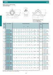
Rolled Ball Screws R-SeriesStandardstockdmφdrφdφL sUnit: mmBall <strong>nut</strong> dimensionsArborScrew shaftOutsidedia.DFlangeA G BLengthL nBolt holeWXOil holeQProject<strong>in</strong>g tubeU V R d 0Bore24 44 17 8 44 34 4.5 M3 × 0.5 17 16 5 10.1 8.1 400 800 RS1212A**30 55 22 10 50 43 6.6 M6 × 1 22 22 7 13.6 11.6 500 1000 1500 RS1616A**Outsidedia.d iStandard lengthL sScrew shaft No.35 68 25 12 59 52 9 M6 × 1 25 27 8 17.3 14.9 500 1000 2000 RS2020A**45 80 31 12 69 63 9 M6 × 1 31 32 10 22.0 19.6 1000 2000 2500 RS2525A**55 100 37 15 84 80 11 M6 × 1 37 40 12 28.0 25.6 1000 2000 3000 RS3232A**70 120 46 18 103 95 14 M6 × 1 46 49 15 35.0 31.8 2000 3000 4000 RS4040A**Remarks 4. Nut assembly with arbor and <strong>the</strong> screw shaft are separated at time of delivery.5. At <strong>the</strong> end of <strong>the</strong> screw shaft reference number where marked with "**", fill with <strong>the</strong> value obta<strong>in</strong>ed by divid<strong>in</strong>g <strong>the</strong>standard screw shaft length by 100 mm.6. Items <strong>in</strong> stock are not applied surface treatment. NSK provides treatment such as phosphate coat<strong>in</strong>g on request.179
Oil hole QTSeals (both ends)45 °45 °4-X drill thru.DφArborAφdiφ φdodmφdrφBCL nHW 180
Rolled Ball Screws R-Seriesdrill thru.StandardstockdmφdrφdφL sUnit: mmScrew shaftStandard lengthScrew shaft No.BoreBall <strong>nut</strong> dimensionsArborFlange Length Bolt hole Oil holeOutsidedia.D A H B L (C ) W X Q T d 0 d iL sOveralllength26 42 29 8 36 3 34 4.5 M3 × 0.5 5.0 8.1 6.1 400 800 RS1006A**29 45 32 8 44 3 37 4.5 M3 × 0.5 5.5 9.6 7.6 400 800 RS1208A**31 50 37 10 40 4 40 4.5 M6 × 1 5.0 11.5 9.5 500 1000 RS1404A**32 50 38 10 40 4 40 4.5 M6 × 1 5.0 11.0 9.0 500 1000 RS1405A**50 80 60 12 61 4 65 6.6 M6 × 1 6.0 13.6 11.6 500 1000 1500 RS1808A**40 60 46 10 40 4 50 4.5 M6 × 1 5.0 17.0 14.6 500 1000 2000 RS2005A**52 82 64 12 61 5 67 6.6 M6 × 1 6.0 16.2 13.8 500 1000 2000 RS2010A**Outsidedia.43 67 50 1040554 55 5.5 M6 × 1 5.0 22.0 19.6 1000 2000 2500 RS2505A**60 96 72 1566965 78 9.0 M6 × 1 7.5 19.0 16.6 1000 2000 2500 RS2510A**50 80 60 1247655 65 6.6 M6 × 1 6.0 25.0 22.6 1000 2000 2500 RS2806A**67 103 78 1567975 85 9.0 M6 × 1 7.5 27.0 24.6 1000 2000 3000 RS3210A**70 110 82 1769995 90 11.0 M6 × 1 8.5 30.0 27.6 1000 2000 3000 RS3610A**76 116 88 17 99 5 96 11.0 M6 × 1 8.5 35.0 31.8 2000 3000 4000 RS4010A**Remarks 4. Items <strong>in</strong> stock are not applied surface treatment. NSK provides treatment such as phosphate coat<strong>in</strong>g on request.5. Seal for those with <strong>the</strong> shaft diameter of 14 mm or less is made of syn<strong>the</strong>tic res<strong>in</strong>. Seal for those with 16 mm orlarger is "Brush-seal."181
182
Rolled Ball Screws R-Series 183
184
Rolled Ball Screws R-Series 185
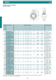
Oil hole QArbor30 °30 °4-X drill thru.AφdodiDφdmφdrφφφEBHML nMW 186
Rolled Ball Screws R-Series4-X drill thru.StandardstockdmφdrφdφL sUnit: mmOutsidedia.DBall <strong>nut</strong> dimensionsFlange LengthA H B E L n MOutsidedia.ArborBolt hole Oil hole BoreW X Q d 0d iStandard lengthL sScrew shaftScrew shaft No.26 44 28 6 9 30 − 35 4.5 M3 × 0.5 10.1 8.1 400 800 RS1212A**33 51 35 10 11 45−342 4.5 M6 × 1 12.2 10.2 500 1000 1500 RS1520A**−32 53 34 10 10 383−42 4.5 M6 × 1 13.6 11.6 500 1000 1500 RS1616A**3−39 62 41 10 11.5 463−50 5.5 M6 × 1 17.3 14.9 500 1000 2000 RS2020A**3−47 74 49 12 13 553−60 6.6 M6 × 1 22.0 19.6 1000 2000 2500 RS2525A**3−58 92 60 12 16 703−74 9 M6 × 1 28.0 25.6 1000 2000 3000 RS3232A**3−73 114 75 15 19.5 85 3.5 −93 11 M6 × 1 35.0 31.8 2000 3000 4000 RS4040A**3.5−90 135 92 20 21.5 107 3.5 −112 14 M6 × 1 44.0 40.8 2000 3000 4000 RS5050A**3.5Remarks 4. Items <strong>in</strong> stock are not applied surface treatment. NSK provides treatment such as phosphate coat<strong>in</strong>g on request.5. The entire length of <strong>the</strong> <strong>nut</strong> becomes longer by "2 x M " for those with a seal. The seal is "Brush-seal."187
Oil hole QArbor30 °30 °4-X drill thru.AdodiDφdmdrφφφφφEBHML nMW 188
Rolled Ball Screws R-Series-X drill thru.StandardstockdmφdrφdφL sBall <strong>nut</strong> dimensionsOutsidedia. Flange LengthD A H B E L n M34−332 50 34 10 10 66−366−341−338 58 40 10 11 81−381−350−341 4.5 M6 × 1 13.5 11.5 500 1000 1500 RS1632A**48 5.5 M6 × 1 17.3 14.9 500 1000 1500 2000 RS2040A**46 70 48 12 13 100 − 58 6.6 M6 × 1 22.0 19.6 1000 2000 2500 RS2550A**3100 − 3−58 92 60 12 15.5 1263−3−ArborBolt hole Oil holeOutsidedia. BoreW X Q d 074 9 M6 × 1 28.0 25.6 1000 2000 3000 4000 RS3264A**73 114 75 15 19 158 3.5 −93 11 M6 × 1 35.0 31.8 2000 3000 4000 5000 RS4080A**3.5Remarks 4. Items <strong>in</strong> stock are not applied surface treatment. NSK provides treatment such as phosphate coat<strong>in</strong>g on request.5. The entire length of <strong>the</strong> <strong>nut</strong> becomes longer by "2 x M " for those with a seal. The seal is "Brush-seal."d iUnit: mmScrew shaftStandard length Screw shaftNo.L s189
190
<strong>Compact</strong> FA Series – E3230Ma<strong>in</strong> features:Next-generation compact <strong>ball</strong> screws offer quiet, high speedoperation performance.A standard stock series assures immediate delivery.15191
<strong>Compact</strong> & SilentFeatures:6 dB less noiseThe noise level of <strong>ball</strong> screws has been reduced by 6 dB,about half of what is sensed by <strong>the</strong> ear. Ball screws subsequentlyproduce a quieter and gentler sound.10%–30% more compact <strong>ball</strong> <strong>nut</strong>The outside diameter of <strong>the</strong> <strong>ball</strong> <strong>nut</strong> is as much as 30%smaller than those of NSK conventional products. This contributesto more compact design of all sorts of equipmentand devices such as th<strong>in</strong>ner XY tables.High-speed operation of up to 5 000 m<strong>in</strong>-1The new <strong>ball</strong> screws offer 1.6 times faster rotational speed thanconventional <strong>ball</strong> screws. They handle speeds up to 5 000 m<strong>in</strong>-1.This capability dramatically expands <strong>the</strong> range of serviceconditions.Note: Please refer to <strong>the</strong> dimension table for details of permissiblerotational speed.New type of contact sealA new model high-performance contact seal m<strong>in</strong>imizes greasedispersion and helps to ma<strong>in</strong>ta<strong>in</strong> a clean work environment.Low-profile designThe low-profile support units especially compatible with <strong>the</strong>compact FA series are available for uniquely space-sav<strong>in</strong>gdesign.Exist<strong>in</strong>g support unit — New low profi le supportGrease fitt<strong>in</strong>g provided as standard equipmentThe new <strong>ball</strong> screws are standardly equipped with a greasefitt<strong>in</strong>g (M5 × 0.8). Lubrication ports are provided <strong>in</strong> 2 placesto facilitate ma<strong>in</strong>tenance. The <strong>ball</strong> screws can be easily connectedto an <strong>in</strong>tegrated lubrication system.As much as 30%more compactShaftdiameterLeadStroke50 100 150 200 300 400 500 600 700 800 1 000 1 200 1 600 2 000Recommended support unitFixed sidesupport unitSimple sidesupport unit105 ●●●●●●●●●10WBK08-01B WBK08S-01B5 ● ● ● ● ● ●1210 ● ● ● ● ●20 ● ● ● ● ●WBK08-01B WBK08S-01B30 ● ● ● ● ●5 ● ● ● ● ● ● ●1510 ● ● ● ● ● ● ● ● ●WBK12-01BWBK10-01B WBK12S-01B20 ● ● ● ● ● ● ● ● ●30 ● ● ● ● ● ● ● ● ●5 ● ● ● ● ● ● ● ●10 ● ● ● ● ● ● ● ● ●2020 ● ● ● ● ● ● ● ● ●30 ● ● ● ● ● ● ● ● ●WBK15-01B WBK15S-01B40 ● ● ● ● ● ● ● ● ●60 ● ● ● ● ● ● ● ● ●5 ● ● ● ● ● ● ● ●10 ● ● ● ● ● ● ● ●2520 ● ● ● ● ● ● ● ●25 ● ● ● ● ● ● ● ●WBK20-01 WBK20S-0130 ● ● ● ● ● ● ● ●50 ● ● ● ● ● ● ● ●O<strong>the</strong>r support units are also available. See last page of catalog for details.Noise data(Microphone was positioned at a distance of 400 mmfor all noise measurements.)192
NSK Ball Screws for standard stock Screw shaft: Ø 10 and 12Screw shaft Ø10Lead 5, 10Ball screw specificationPreload typeOversize <strong>ball</strong> preload (P-preload)Ball diameter/screw shaft root diameter 2.000/8.2Accuracy grade/axial play C5/0Factory pre-packed greaseNSK grease PS2Recommended support unitWBK08-01B (square, fixed side)WBK08S-01B (square, simple side)WBK08-11B (round, fixed side)Reference numberScrewshaftdiameterdLeadBasic load rat<strong>in</strong>gs (N)DynamicC aStaticC 0aStrokeMax.Nom<strong>in</strong>alL 1-LNutlengthLScrew shaft dimensionsLead accuracyTarget value Error VariationL 1 L 2 L 3 T e p υ uShaft runout, CDynamic preload torque(N·cm) ✽1Permissible rotationalspeed (m<strong>in</strong> –1 ) ✽ 2Fixed-SimplePSS1005N1D0171 50 83 112 125 1710.020 0.018 0.030 0.7 – 3.3PSS1005N1D0221 100 133 162 175 2210.020 0.018 0.045 0.7 – 3.3PSS1005N1D0321 5 2 930 4 790 200 233 29 262 275 3210.023 0.018 0.060 0.6 – 4.3 5 000PSS1005N1D0421 300 333 362 375 4210.025 0.020 0.070 0.6 – 4.3PSS1005N1D0521 10 400 433 462 475 521 0 0.027 0.020 0.085 0.4 – 4.9PSS1010N1D0221 100 130 162 175 2210.020 0.018 0.045 0.7 – 3.3PSS1010N1D032110 1 970 3 010200 23032262 275 3210.023 0.018 0.060 0.6 – 4.35 000PSS1010N1D0421300 330362 375 4210.025 0.020 0.070 0.6 – 4.30.027 0.020 0.085 0.4 – 4.9✽ 1. Indicates <strong>ball</strong> screw preload control value. About 2.0 N·cm of torque is added due to high performance seal. ✽ 2. Contact NSK if permissible rotational speed is to be exceeded. ✽ 3. Service temperature range is -20˚C to 80˚CScrew shaft Ø12Lead 5, 10, 20, 30Ball screw specificationPreload typeOversize <strong>ball</strong> preload (P-preload)Ball diameter/screw shaft root diameter 2.000/10.2Accuracy grade/axial play C5/0Factory pre-packed greaseNSK grease PS2193
NSK Ball Screws for standard stock Screw shaft: Ø 15Screw shaft Ø15Lead 5, 10Screw shaft Ø15Lead 20, 30194
NSK Ball Screws for standard stock Screw shaft: Ø 20Screw shaft Ø20Lead 5, 10, 20, 30, 40, 60195
φNSK Ball Screws for standard stock Screw shaft: Ø 25Screw shaft Ø25Lead 5, 10, 20, 25, 30, 50196
NSK Ball Screws for standard stock197
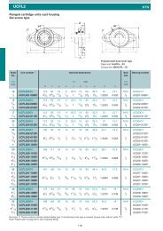
Part No. Part Remarks (surface treatment, grease)Bear<strong>in</strong>g hous<strong>in</strong>gTriiron tetroxide film➀Angular contact <strong>ball</strong> bear<strong>in</strong>g PS2Oil sealCoverTriiron tetroxide film➁ Spacer➂ Lock <strong>nut</strong> Triiron tetroxide film➃Setscrew Triiron tetroxide film➄ Deep groove <strong>ball</strong> bear<strong>in</strong>g Comes with support side, PS2➅ Snap r<strong>in</strong>g Triiron tetroxide filmO<strong>the</strong>r mach<strong>in</strong>e screws are ei<strong>the</strong>r made of sta<strong>in</strong>less steel or coarted withtriiron tetroxide film.Part No. Part Remarks (surface treatment, grease)➀ Bear<strong>in</strong>g hous<strong>in</strong>g Triiron tetroxide film➁ Deep groove <strong>ball</strong> bear<strong>in</strong>g PS2➂ Snap r<strong>in</strong>g Triiron tetroxide film198
Low-profile Support Units for <strong>Compact</strong> FA SeriesFixed side support unit (square type)Simple side support unit199
<strong>Compact</strong> FA SeriesSquare type and Round typeFixed side support unit (round type)Specifications of support unit200
WBK Support UnitsSupport unitsq ClassificationBall screw support units are classified <strong>in</strong>to categories by <strong>the</strong>irshape. Select <strong>the</strong> type that is appropriate for you to use.w Features• Short delivery time: Standardized items <strong>in</strong> stock• Use most suitable bear<strong>in</strong>gsOn <strong>the</strong> fixed support side, <strong>the</strong> angular contact <strong>ball</strong> bear<strong>in</strong>gis used. It has great rigidity and low friction torquewhich match <strong>the</strong> rigidity of <strong>the</strong> <strong>ball</strong> screw.The thrust angular contact <strong>ball</strong> bear<strong>in</strong>g with high precisionand great rigidity is ano<strong>the</strong>r choice for <strong>the</strong> fixedsupport side.• High dust prevention, and low friction torqueOil seal is <strong>in</strong>stalled <strong>in</strong> small clearance on <strong>the</strong> fixed supportside. A deep-groove <strong>ball</strong> bear<strong>in</strong>g with a shield onboth sides is used on <strong>the</strong> simple support side. This m<strong>in</strong>imizesfriction torque.• Lock <strong>nut</strong> is provided.A lock <strong>nut</strong> of f<strong>in</strong>e grade f<strong>in</strong>ish is provided to fix <strong>the</strong>bear<strong>in</strong>g with high precision.16201
202
WBK Support UnitsSupport units1 ClassificationBall screw support units are classified <strong>in</strong>tocategories by <strong>the</strong>ir shape (Table I-6.6). Select <strong>the</strong>type that is appropriate for you to use.2 Features• Short delivery time: Standardized items <strong>in</strong> stock• Use most suitable bear<strong>in</strong>gsOn <strong>the</strong> fixed support side, <strong>the</strong> angular contact <strong>ball</strong>bear<strong>in</strong>g is used. It has great rigidity and low frictiontorque which match <strong>the</strong> rigidity of <strong>the</strong> <strong>ball</strong> screw.The thrust angular contact <strong>ball</strong> bear<strong>in</strong>g with highprecision and great rigidity is ano<strong>the</strong>r choice for <strong>the</strong>fixed support side.• High dust prevention, and low friction torqueOil seal is <strong>in</strong>stalled <strong>in</strong> small clearance on <strong>the</strong> fixedsupport side. A deep-groove <strong>ball</strong> bear<strong>in</strong>g with ashield on both sides is used on <strong>the</strong> simple supportside. This m<strong>in</strong>imizes friction torque.• Lock <strong>nut</strong> is provided.A lock <strong>nut</strong> of f<strong>in</strong>e grade f<strong>in</strong>ish is provided to fix <strong>the</strong>bear<strong>in</strong>g with high precision.3 Reference number and applicable <strong>ball</strong> screwSupport unit product code(For light load) WBK 08 S-01Nom<strong>in</strong>al sizeSupport side code No code:Fixed support sideSSF:Simple support sideR:Fixed support side (support kit)Design serial numberNom<strong>in</strong>al size(For heavy load) WBK 25 DF-31Bear<strong>in</strong>g comb<strong>in</strong>ationDF (duplex), DFD (triplex), DFF (quadruple)Design serial numberDetails for <strong>the</strong> new NSK Low Profile Support Units you willf<strong>in</strong>d on page 154 and follow<strong>in</strong>g.203
The table below show "shaft diameter/lead comb<strong>in</strong>ations" of standard <strong>ball</strong> screws that are applicable tosupport units.Support units for light load and applicable "shaft diameter/lead comb<strong>in</strong>ations"Support unit / reference number"Shaft diameter/lead comb<strong>in</strong>ations"SquareRoundof standard <strong>ball</strong> screwsFixed support side Simple support sidethat are applicable to support unitFixed support side(driv<strong>in</strong>g motor side) (opposite to driv<strong>in</strong>g motor)WBK06-01A − WBK06-11 φ4 × 1, φ6 × 1Light load / small equipmentWBK08-01A WBK08S-01 WBK08-11 φ8 × 1, φ8 × 1.5, φ8 × 2, φ10 × 2, φ10 × 2.5WBK10-01A WBK10S-01 WBK10-11 φ10 × 4, φ12 × 2, φ12 × 2.5, φ12 × 5, φ12 × 10WBK12-01A WBK12S-01 WBK12-11φ14 × 5, φ14 × 8, φ15 × 10, φ15 × 20, φ16 × 2φ16 × 2.5, φ16 × 5, φ16 × 16, φ16 × 32WBK15-01A WBK15S-01 WBK15-11 φ20 × 4, φ20 × 5, φ20 × 10, φ20 × 20, φ20 × 40WBK20-01 WBK20S-01 WBK20-11φ20 × 4, φ20 × 5, φ20 × 6, φ20 × 10, φ20 × 20φ25 × 25, φ25 × 50, φ28 × 5, φ28 × 6WBK25-01 WBK25S-01 WBK25-11φ32 × 5, φ32 × 6, φ32 × 8, φ32 × 10φ32 × 25, φ32 × 32,Remarks 1. Reference number is based on <strong>the</strong> bear<strong>in</strong>g bore on <strong>the</strong> fixed support side.2. Please note that <strong>the</strong> reference numbers 12 or below on <strong>the</strong> simple-support side do not match <strong>the</strong> bore of<strong>the</strong> deep-groove <strong>ball</strong> bear<strong>in</strong>g <strong>in</strong> use.Support units for heavy load and applicable "shaft diameter/lead comb<strong>in</strong>ations"Support unit / reference numberHeavy load / mach<strong>in</strong>e toolsFixed support side(drive motor side)Fixed support side(opposite to drive motor)WBK30DF-31 WBK25DF-31 φ36 × 10WBK30DFD-31 WBK25DFD-31 φ36 × 10, φ40 × 10"Shaft diameter/lead comb<strong>in</strong>ations"of standard <strong>ball</strong> screwsthat are applicable to <strong>the</strong> support unitWBK30DF-31 WBK30DF-31 φ40 × 5, φ40 × 8, φ40 × 10, φ40 × 12WBK30DFD-31 WBK30DFD-31 φ40 × 12WBK35DF-31 WBK35DF-31 φ45 × 10WBK40DF-31 WBK40DF-31 φ50 × 10WBK40DFD-31 WBK40DFD-31 φ50 × 10204
WBK Support Units 205
Square type Reference number: WBK06-01A1 23 4 5 6(22)9.5φ6φ3.5101020Section X-XRound type Reference number: WBK06-111 23 4 5 63.59.5(22)X4-2.9 drill thru.,C'bore 5.5 X 3.5PCD 28 (For M2.5 bolt)45 °-0.007-0.02022g6φ9.5φ6φφX3514 1413712 SpannerAssembly example 120(5.5)28Section X-X206
WBK Support UnitsWBK06(12)3018Unit: mmStandardstock2-5.5 drill thru.,C'bore 9.5 X 11X130-0.05255712X12 SpannerA424.5(22)2.5Parts listNumber Name of part Quantity Remarks(1.5)7 13 (6.5) Assembly example 2123456Bear<strong>in</strong>g hous<strong>in</strong>g 1 With oil sealBear<strong>in</strong>gReta<strong>in</strong><strong>in</strong>g cover 1Spacer 1One set 706ATYDFC7P5Lock <strong>nut</strong> 1 For M6, tighten<strong>in</strong>g torque 245N •cm {25kgf •cm}Set screw 1 M3, with a set piece (pad)Remarks 1. When <strong>in</strong>stall<strong>in</strong>g a square support unit, place A side to <strong>the</strong>base. Use a spacer if necessary to adjust height.2. Components 1, 2, 3 are assembled <strong>in</strong>to a unit. Do notdisassemble.3. An appropriate volume of grease is packed <strong>in</strong> <strong>the</strong> supportunit.4. Tighten <strong>the</strong> set screw 6 after adjustment.207
Square type Reference number: WBK08-01A (fixed support side); WBK08S-01(simple support side)(13.5)3825Y9 8 72-6.6 drill thru.,C'bore 11 X 122617326φ0-0.05YSimple support sideB""5215WBK08S-01Section Y-YRound type Reference number: WBK08-118 71 23 4 5 64 (26)10Z4-3.4 drill thru.,C'bore 6.5 X 4PCD 35 (For M3 bolt)45 °17.56φ-0.007-0.02028g6φ11.5φ8φφZ4317.514914 SpannerAssembly example 123(7) 35Section Z-Z208
WBK Support UnitsWBK08Unit: mmStandardstock1 23 4 5 6(13.5)3825(26)2-6.6 drill thru.,C'bore 11 X 12X411.5811.5 11.5X239156φφFixed support side14 Spanner0-0.051732A52Section X-XWBK08-01AParts list5(26)Number Name of part Quantity Remarks41Bear<strong>in</strong>g hous<strong>in</strong>g 1 With oil seal on fixed support side2Bear<strong>in</strong>gOne set 706ATYDFC7P53Reta<strong>in</strong><strong>in</strong>g cover 14Spacer 15Lock <strong>nut</strong> 1 For M8, tighten<strong>in</strong>g torque 490N •cm {50 kgf •cm}6Set screw 1 M3, with a set piece (pad)7Bear<strong>in</strong>g 1 606ZZ9141.58Assembly example 289Reta<strong>in</strong><strong>in</strong>g r<strong>in</strong>g 1Bear<strong>in</strong>g hous<strong>in</strong>g 1 Simple support side (only square type)Remarks 1. When <strong>in</strong>stall<strong>in</strong>g a square support unit, place A and B sidesto <strong>the</strong> base. Use a spacer if necessary to adjust height.2. Components 1, 2, 3 are assembled <strong>in</strong>to a unit. Do notdisassemble.3. An appropriate volume of grease is packed <strong>in</strong> <strong>the</strong> supportunit.4. Tighten <strong>the</strong> set screw 6 after adjustment.209
Square type Reference number: WBK10-01A (fixed support side); WBK10S-01 (simple support side)521098(17)36Y2-9 drill thru.,C'bore 14 X 1135438φ0-0.0525Simple support sideYB""7020WBK10S-01Section Y-YRound type Reference number: WBK10-119 81 25 6 75 (29.5)124-4.5 drill thru.,C'bore 8 X 4PCD 42 (For M4 bolt)45 °Z8φ-0.009-0.02534g6φ14φ10φ20 °Zφ52212143 4171017 SpannerAssembly example 127(7.5)42Section Z-Z210
WBK Support UnitsWBK1012525 6 752Unit: mmStandardstock(17) (29.5)36(17)36X 11X2-9 drill thru.,C'bore 14 X 11X0-0.0543254314101010181888φφFixed support side0-0.05256124X17 Spanner34AX17 SpannerA246(5.5) 7070Section X-XWBK10-01A6 (29.5)40.5Assembly example 210 17 (8.5)Assembly example 212345678910Parts listNumber Name of part Quantity RemarksBear<strong>in</strong>g hous<strong>in</strong>g 1 With oil seal on fixed support sideBear<strong>in</strong>gReta<strong>in</strong><strong>in</strong>g cover 1One set 7000ATYDFC8P5Hexagon socket head capscrew or cross recessedpan head screw4 M4Spacer 1Lock <strong>nut</strong> 1 For M10, tighten<strong>in</strong>g torque 930N •cm {95 kgf •cm}Set screw 1 M4 with a set piece (pad)Bear<strong>in</strong>g 1 608ZZReta<strong>in</strong><strong>in</strong>g r<strong>in</strong>g 1Bear<strong>in</strong>g hous<strong>in</strong>g 1 Simple support side (only square type)Remarks 1. When <strong>in</strong>stall<strong>in</strong>g a square support unit, place A and B sidesto <strong>the</strong> base. Use a spacer if necessary to adjust height.2. Components 1, 2, 3 are assembled <strong>in</strong>to a unit. Do notdisassemble.3. An appropriate volume of grease is packed <strong>in</strong> <strong>the</strong> supportunit.4. Tighten <strong>the</strong> set screw 7 after adjustment.211
Square typeReference umber: WBK12-01 (fixed support side); WBK12S-01 (simple support side)521098(17)36Y2-9 drill thru.,C'bore 14 X 114310φ350-0.0525Simple support sideBY70"20"WBK12S-01Section Y-YRound type Reference number: WBK12-119 81 25 6 75 (29.5)124-4.5 drill thru.,C'bore 8 X 4PCD 44 (For M4 bolt)45 °Z2210φ-0.009-0.02536g6φ15φ12φ20 °Zφ5422171043419 SpannerAssembly example 127(7.5)44Section Z-Z212
WBK Support UnitsWBK12Unit: mmStandardstock12525 6 752(29.5) 36(17)362-9 drill thru.,C'bore 14 X 11X43151281018φφ43Fixed support side0-0.052564123A4X19 SpannerA246(5.5)70Section X-XWBK12-01AParts listNumber Name of part Quantity Remarks6(29.5)1Bear<strong>in</strong>g hous<strong>in</strong>g 1 With oil seal on fixed support side42Bear<strong>in</strong>gOne set 7001ATYDFC8P534Reta<strong>in</strong><strong>in</strong>g cover 1Hexagon socket head capscrew or cross recessed 4 M4pan head screw5Spacer 16Lock <strong>nut</strong> 1 For M12, tighten<strong>in</strong>g torque 1370N •cm {140 kgf •cm}7Set screw 1 M4 with a set piece (pad)10170.5(8.5)Assembly example 28910Bear<strong>in</strong>g 1 6000ZZReta<strong>in</strong><strong>in</strong>g r<strong>in</strong>g 1Bear<strong>in</strong>g hous<strong>in</strong>g 1 Simple support side (only square type)Remarks 1. When <strong>in</strong>stall<strong>in</strong>g a square support unit, place A and B sidesto <strong>the</strong> base. Use a spacer if necessary to adjust height.2. Components 1, 2, 3 are assembled <strong>in</strong>to a unit. Do notdisassemble.3. An appropriate volume of grease is packed <strong>in</strong> <strong>the</strong> supportunit.4. Tighten <strong>the</strong> set screw 7 after adjustment.213
Square type Reference number: WBK15-01A (fixed support side); WBK15S-01(simple support side)60109819.5 41Y2-9 drill thru.,C'bore 14 X 1130504015φ0-0.05Simple support sideBY80""20WBK15S-01Section Y-YRound type Reference number: WBK15-119 81 25 6 76 (38)114-5.5 drill thru.,C'bore 9.5 X 6PCD 50 (For M5 bolt)45 °Z2615φ-0.009-0.02540g6φ19.5φ15φ20 °Zφ6326176153422 SpannerAssembly example 132(12)52Section Z-ZWBK15-11214
WBK Support UnitsWBK15Unit: mmStandardstock1 25 6 7(38)2-11 drill thru.,C'bore 17 X 15(19.5)X60415019.515102010φφFixed support side0-0.05305 312.5(12)4 X22 Spanner80ASection X-XWBK15-01AParts listNumber Name of part Quantity Remarks8(38)1Bear<strong>in</strong>g hous<strong>in</strong>g 1 With oil seal on fixed support side72Bear<strong>in</strong>gOne set 7002ATYDFC8P53Reta<strong>in</strong><strong>in</strong>g cover 14Hexagon socked headcap screw4 M415174(14)Assembly example 25678910Spacer 1Lock <strong>nut</strong> 1 For M15, tighten<strong>in</strong>g torque 2350N •cm {240 kgf •cm}Set screw 1 M4 with a set piece (pad)Bear<strong>in</strong>g 1 6002ZZReta<strong>in</strong><strong>in</strong>g r<strong>in</strong>g 1Bear<strong>in</strong>g hous<strong>in</strong>g 1 Simple support side (only square type)Remarks 1. When <strong>in</strong>stall<strong>in</strong>g a square support unit, place A and B sidesto <strong>the</strong> base. Use a spacer if necessary to adjust height.2. Components 1, 2, 3 are assembled <strong>in</strong>to a unit. Do notdisassemble.3. An appropriate volume of grease is packed <strong>in</strong> <strong>the</strong> supportunit.4. Tighten <strong>the</strong> set screw 7 after adjustment.215
Square typeReference number: WBK20-01 (fixed support side); WBK20S-01 (simple support side)751098(19.5)56Y2-11 drill thru.,C'bore 17 X 1545305820φ0-0.05YSimple support sideB95""26Section Y-YWBK20S-01Round type Reference number: WBK20-119 81 25 6 710 (52)204-6.6 drill thru.,C'bore 11 X 10PCD 70 (For M6 bolt)45 °Z20φ-0.010-0.02957g6φ2520φφ22.5 °Zφ8534341034302230 SpannerAssembly example 152(10)68Section Z-ZWBK20-11216
WBK Support UnitsWBK20(17)Unit: mmStandardstock1 25 6 710(52)10 227575X 1525φX20φ56(19.5)4-11 drill thru.,C'bore 17 X 15X56(19.5)Fixed support side13151315281030-0.05305842 104 X4 X30 SpannerSection X-XWBK20-0130 Spanner95AParts listNumber Name of part Quantity Remarks148(52)123Bear<strong>in</strong>g hous<strong>in</strong>g 1 With oil seal on fixed support sideBear<strong>in</strong>gOne set 7204ATYDFC8P5Reta<strong>in</strong><strong>in</strong>g cover 14Hexagon socked headcap screw4 M65Spacer 16Lock <strong>nut</strong> 1 For M20, tighten<strong>in</strong>g torque 4700N •cm {480 kgf •cm}7Set screw 1 M4 with a set piece (pad)8Bear<strong>in</strong>g 1 6204ZZ22 301(14)Assembly example 29 Reta<strong>in</strong><strong>in</strong>g r<strong>in</strong>g 110 Bear<strong>in</strong>g hous<strong>in</strong>g 1 Simple support side (only square type)Remarks 1. When <strong>in</strong>stall<strong>in</strong>g a square support unit, place A and B sidesto <strong>the</strong> base. Use a spacer if necessary to adjust height.2. Components 1, 2, 3 are assembled <strong>in</strong>to a unit. Do notdisassemble.3. An appropriate volume of grease is packed <strong>in</strong> <strong>the</strong> supportunit.4. Tighten <strong>the</strong> set screw 7 after adjustment.217
Square typeReference number: WBK25-01 (fixed support side); WBK25S-01 (simple support side)1098(17)8519.5 66Y2-11 drill thru.25356825φ0-0.05YSimple support sideB105""30Section Y-YWBK25S-01Round type Reference number: WBK25-119 81 25 6 710 (60)204-9 drill thru.,C'bore 15 X 13PCD 80 (For M8 bolt)45 °Z25φ-0.010-0.02963g622.5 °Z39.5φ32φ25φφ9839.53013273436 SpannerAssembly example 157(13)79Section Z-Z218
WBK Support UnitsWBK251 25 6 7(60)4830 9"4-11 drill thru.Unit: mmStandardstock"92-7.8 drill thru.(Pilot hole for 8 dia. tapered p<strong>in</strong>.)32φ25φX856619.5)Fixed support side331448133250-0.053568Section X-XWBK25-014X36 Spanner105AParts list1710(60)Number Name of part Quantity Remarks1 Bear<strong>in</strong>g hous<strong>in</strong>g 1 With oil seal on fixed support side2 Bear<strong>in</strong>gOne set 7204ATYDFC8P53 Reta<strong>in</strong><strong>in</strong>g cover 14Hexagon socked headcap screw4 M65Spacer 16Lock <strong>nut</strong> 1 For M25, tighten<strong>in</strong>g torque 8400N •cm {860 kgf •cm}7Set screw 1 M6 with a set piece (pad)27 304(20)Assembly example 289Bear<strong>in</strong>g 1 6205ZZReta<strong>in</strong><strong>in</strong>g r<strong>in</strong>g 110Bear<strong>in</strong>g hous<strong>in</strong>g 1 Simple support side (only square type)Remarks 1. When <strong>in</strong>stall<strong>in</strong>g a square support unit, place A and B sidesto <strong>the</strong> base. Use a spacer if necessary to adjust height.2. Components 1, 2, 3 are assembled <strong>in</strong>to a unit. Do notdisassemble.3. An appropriate volume of grease is packed <strong>in</strong> <strong>the</strong> supportunit.4. Tighten <strong>the</strong> set screw 7 after adjustment.219
Square typeReference number: WBK12SF-01 (Simple support side: For VFA1210)Hous<strong>in</strong>g52362-9 drill thru.,C'bore 14 X 11(For M8 bolt)Ball bear<strong>in</strong>g(6001ZZ)43120-0.05025""35φ70 20""2-C type <strong>in</strong>ternalreta<strong>in</strong><strong>in</strong>g r<strong>in</strong>g(For 28 bore)Square type Reference number: WBK15SF-01 (Simple support side: For VFA1510)Hous<strong>in</strong>g52362-9 drill thru.,C'bore 14 X 11(For M8 bolt)Ball bear<strong>in</strong>g(6902ZZ)15430-0.05025""35φ70 20""2-C type <strong>in</strong>ternareta<strong>in</strong><strong>in</strong>g r<strong>in</strong>g(For 28 bore220
WBK Support Unitsrill thru.,e 14 X 11M8 bolt)Ball bear<strong>in</strong>g(6001ZZ)Unit: mmWBK12SFStandardstock12φ""202-C type <strong>in</strong>ternalreta<strong>in</strong><strong>in</strong>g r<strong>in</strong>g(For 28 bore)Number Name of part Quantity Remarks123Bear<strong>in</strong>g hous<strong>in</strong>g 1 Simple support sideBear<strong>in</strong>g 1 6001ZZReta<strong>in</strong><strong>in</strong>g r<strong>in</strong>g 2Remarks 1. When <strong>in</strong>stall<strong>in</strong>g <strong>the</strong> square support unit, place side A to<strong>the</strong> base and <strong>in</strong>stall <strong>the</strong> unit <strong>in</strong> <strong>the</strong> vertical direction. Use aspacer if necessary to adjust height.2. Do not disassemble <strong>the</strong> support unit.3. An appropriate volume of grease is packed <strong>in</strong> <strong>the</strong> bear<strong>in</strong>g.Applicable <strong>ball</strong> screw : VFA1210Parts list (WBK12SF-01)drill thru.,re 14 X 11r M8 bolt)Ball bear<strong>in</strong>g(6902ZZ)15φ""202-C type <strong>in</strong>ternalreta<strong>in</strong><strong>in</strong>g r<strong>in</strong>g(For 28 bore)Number Name of part Quantity Remarks123Bear<strong>in</strong>g hous<strong>in</strong>g 1 Simple support sideBear<strong>in</strong>g 1 6902ZZReta<strong>in</strong><strong>in</strong>g r<strong>in</strong>g 2Parts list (WBK15SF-01)Remarks 1. When <strong>in</strong>stall<strong>in</strong>g <strong>the</strong> square support unit, place side A to<strong>the</strong> base and <strong>in</strong>stall <strong>the</strong> unit <strong>in</strong> <strong>the</strong> vertical direction. Use aspacer if necessary to adjust height.2. Do not disassemble <strong>the</strong> support unit.3. An appropriate volume of grease is packed <strong>in</strong> <strong>the</strong> bear<strong>in</strong>g.Applicable <strong>ball</strong> screw : VFA1510, VFA1520221
Round type Reference number: WBK04R-11212.5 5Mount<strong>in</strong>g surface4514G5X612.5φφ4φ130-0.1φ2519φ1039Section X-X2-3.4 drill thru.(For M3 bolt)XRound type Reference number: WBK06R-11212.5 6.8Mount<strong>in</strong>g surface4519G5X10φ17φ6φ180-0.1φ302412φ311Section X-X2-3.4 drill thru.(For M3 bolt)X222
WBK Support UnitsWBK∗∗R514Unit: mmParts list (WBK04R-11)Number Name of part Quantity RemarksStandardstock1Bear<strong>in</strong>g hous<strong>in</strong>g 1X2Bear<strong>in</strong>g One set F694ZZ3Spacer 12519φ104Lock <strong>nut</strong> 1 For M4, tighten<strong>in</strong>g torque 98N •cm {10 kgf •cm}5Set screw to secure <strong>the</strong> lock <strong>nut</strong> 1 M2.5 with a set piece (pad)2-3.4 drill thru.(For M3 bolt)XRemarks 1. Adjust phases of <strong>the</strong> bear<strong>in</strong>g and <strong>the</strong> lock <strong>nut</strong> at time ofassembly, and secure <strong>the</strong>m <strong>in</strong> <strong>the</strong> state when <strong>the</strong> run outof <strong>the</strong> flange mount<strong>in</strong>g surface is m<strong>in</strong>imal.2. Assembled to an arbor (M4 bolt, <strong>nut</strong>) at time of delivery.Remove it from <strong>the</strong> arbor and move to <strong>the</strong> <strong>ball</strong> screw shaftend before use.3. An appropriate volume of grease is packed <strong>in</strong>to <strong>the</strong>bear<strong>in</strong>g.4. Slightly tighten <strong>the</strong> set screw 5 after adjustment.Applicable <strong>ball</strong> screw : RMA060119Parts list (WBK06R-11)Number Name of part Quantity RemarksX1Bear<strong>in</strong>g hous<strong>in</strong>g 12Bear<strong>in</strong>g One set F696ZZ3024φ1234Spacer 1Lock <strong>nut</strong> 1 For M6, tighten<strong>in</strong>g torque 118N •cm {12 kgf •cm}5Set screw to secure <strong>the</strong> lock <strong>nut</strong> 1 M2.5 with a set piece (pad)2-3.4 drill thru.(For M3 bolt)XRemarks 1. Adjust phases of <strong>the</strong> bear<strong>in</strong>g and <strong>the</strong> lock <strong>nut</strong> at time ofassembly, and secure <strong>the</strong>m <strong>in</strong> <strong>the</strong> state when <strong>the</strong> run outof <strong>the</strong> flange mount<strong>in</strong>g surface is m<strong>in</strong>imal.2. Assembled to an arbor (M6 bolt, <strong>nut</strong>) at time of delivery.Remove it from <strong>the</strong> arbor and move to <strong>the</strong> <strong>ball</strong> screw shaftend before use.3. An appropriate volume of grease is packed <strong>in</strong>to <strong>the</strong>bear<strong>in</strong>g.4. Slightly tighten <strong>the</strong> set screw 5 after adjustment.Applicable <strong>ball</strong> screw : RMA0801, RMA0801.5, RMA0802223
224
WBK Support Units(2) Dimensions of support unit: heavy-load / for mach<strong>in</strong>e toolsSupport units for heavy-load / mach<strong>in</strong>e tools use a thrust angular contact <strong>ball</strong>bear<strong>in</strong>g (TAC Series) with high rigidity and accuracy. The thrust angular contact <strong>ball</strong>bear<strong>in</strong>g has very suitable functions and structure as a <strong>ball</strong> screw support bear<strong>in</strong>g.There are three comb<strong>in</strong>ations as shown below.DF comb<strong>in</strong>ation DFD comb<strong>in</strong>ation DFF comb<strong>in</strong>ationParts list1372 6 4 5 8Part number Part name Quantity1 Hous<strong>in</strong>g 12 Reta<strong>in</strong><strong>in</strong>g cover 13High accuracy thrust angular contact <strong>ball</strong> bear<strong>in</strong>gOne set4Dust seal 25678Collar 2Preload bolt 6 or 8ShimOne setLock <strong>nut</strong> 1BARemarks1. Mount sections A and B to <strong>the</strong> mach<strong>in</strong>e base.2. NSK support units are precisely preloaded andadjusted. Components 1, 2, 3, 4, 6, 7 areassembled <strong>in</strong>to a unit. Do not disassemble.3. Grease is packed <strong>in</strong>to support units.4. Lock <strong>nut</strong> 8 is exclusively prepared for <strong>ball</strong> screw.The end face of <strong>the</strong> <strong>nut</strong> is <strong>in</strong> strict control be<strong>in</strong>gprecisely perpendicular to <strong>the</strong> V thread. Secure<strong>the</strong> lock <strong>nut</strong> us<strong>in</strong>g <strong>the</strong> set screw.Lock <strong>nut</strong> is also available as an accessory (Seepage 180. Refer to general catalogue E3161"Precision Mach<strong>in</strong>e Components" for high precisiontrust angular contact <strong>ball</strong> bear<strong>in</strong>g (TAC Series).225
L L 34-P ∗ tap, Q(both siDg6φd1 ∗ H7φdφd1 ∗ H7φD2φD1φD3φMdφMl ∗l ∗L 3 L 4L 5L 1 L 2L6-X driC'boreLock <strong>nut</strong>Dimensions of bear<strong>in</strong>g seatSupport unitBasic dynamicSupport unitNo.load rat<strong>in</strong>g C ad D D 1 D 2 L L 1 L 2 A W X Y Z d 1 * l* V* P* Q* N {kgf}WBK 17DF-31 17 70 106 72 60 32 15 80 88 9 14 8.5 45 3 58 M5 10 21900 2240WBK 20DF-31 20 70 106 72 60 32 15 80 88 9 14 8.5 45 3 58 M5 10 21900 2240WBK 25DF-31 66 33 28500 291025 85 130 90 18 100 110 11 17.5 11 57 4 70 M6 12WBK 25DFD-31 81 48 46500 4700WBK 30DF-3166 33 29200 298030 85 130 9018 100 110 11 17.5 11 57 4 70 M6 12WBK 30DFD-31 81 48 47500 4850WBK 35DF-31 66 33 31000 3150WBK 35DFD-31 35 95 142 102 81 48 18 106 121 11 17.5 11 69 4 80 M6 12 50500 5150WBK 35DFF-31 96 48 50500 5150WBK 40DF-31 66 33 31500 3250WBK 40DFD-31 40 95 142 102 81 48 18 106 121 11 17.5 11 69 4 80 M6 12 51500 5250WBK 40DFF-31 96 48 51500 5250Remarks 1. RigidityValues <strong>in</strong> <strong>the</strong> Table are <strong>the</strong>oretical values obta<strong>in</strong>ed from <strong>the</strong> elastic deformation between <strong>the</strong> groove and <strong>the</strong> <strong>ball</strong>s.2. Start<strong>in</strong>g torqueStart<strong>in</strong>g torque <strong>in</strong>dicates torque due to <strong>the</strong> preload of <strong>the</strong> bear<strong>in</strong>g. It does not <strong>in</strong>clude seal torque.3. The tolerance of <strong>the</strong> shaft bear<strong>in</strong>g seatWe recommend "h5 grade of <strong>the</strong> fits tolerance.226
WBK Support Units45 °45 °30 °15 °15 °30 °Standardstock4-P ∗ tap, Q ∗ deep.(both sides)4-P ∗ tap, Q ∗ deep.(both sides)V ∗WV ∗W6-X drill thru.,C'bore Y X Z"A"8-X drill thru.,C'bore Y X Z"A"Bear<strong>in</strong>g bore d 30=>Bear<strong>in</strong>g bore d => 35Unit: mmPermissibleaxial loadPreloadAxial rigidityStart<strong>in</strong>g torqueLock <strong>nut</strong>Bear<strong>in</strong>g seatfor unitN {kgf} N {kgf} N/μm {kgf/μm} N •m {kgf •m} M D 3 L 3 d L 4 L 526600 2710 2150 220 750 75 14.0 1.5 M17×1.0 37 18 17 81 2326600 2710 2150 220 750 75 14.0 1.5 M20×1.0 40 18 20 81 2340500 4150 3150 320 1000 100 23.0 289M25×1.5 45 20 2581500 8300 4300 440 1470 150 31.0 3 1042643000 4400 3350 340 1030 105 24.0 2.589M30×1.5 50 20 3086000 8800 4500 460 1520 155 33.0 3 1042650000 5100 3800 390 1180 120 28.0 3 92100000 10200 5200 530 1710 175 37.0 4 M35×1.5 55 22 35 107 30100000 10200 7650 780 2350 240 55.0 5.5 12252000 5300 3900 400 1230 125 28.0 3 92104000 10600 5300 540 1810 185 38.0 4 M40×1.5 60 22 40 107 30104000 10600 7850 800 2400 245 57.0 5.5 122Remarks 4. Dimensions with * (asterisk) mark*Pilot diameter and tapped screws marked with "asterisk *" are used for seal unit <strong>in</strong>stallation for NSK standard hollowshaft <strong>ball</strong> screws. They also can be used for dust cover and damper <strong>in</strong>stallation.5. Grease is packed <strong>in</strong>to <strong>the</strong> bear<strong>in</strong>g. It is not necessary to apply grease before use. We recommend "h5 grade of <strong>the</strong> fitstolerance.227
φIn addition to <strong>the</strong> support units, NSK has o<strong>the</strong>r components for <strong>the</strong> <strong>ball</strong> screw as shown below.Lock <strong>nut</strong>sBall screw support bear<strong>in</strong>g must be <strong>in</strong>stalled with m<strong>in</strong>imum <strong>in</strong>cl<strong>in</strong>ation. NSK lock <strong>nut</strong>s exclusive for<strong>ball</strong> screw help to reduce this <strong>in</strong>cl<strong>in</strong>ation.X1-SSet screwB 1FGdφDφXBBrass padFSection X-XA Type Shapes and dimensionsA Type lock <strong>nut</strong>sUnit: mmLock <strong>nut</strong> reference number M D F B d B 1 S Tighten<strong>in</strong>g torque N • m (for reference)WBK06L-01 M6 × 0.75 14.5 12 5 10 2.7 M3, with brass made set piece 245WBK08L-01 M8 × 1.0 17 14 6.5 13 4 M3, with brass made set piece 490WBK10L-01 M10 × 1.0 20 17 8 16 5 M4, with brass made set piece 930WBK12L-01 M12 × 1.0 22 19 8 17 5 M4, with brass made set piece 1350WBK15L-01 M15 × 1.0 25 22 10 21 6 M4, with brass made set piece 2350WBK20L-01 M20 × 1.0 35 30 13 26 8 M4, with brass made set piece 4700WBK25L-01 M25 × 1.0 42 36 16 34 10 M6, with brass made set piece 8400Remarks: Insert a set piece (brass pad) and tighten <strong>the</strong> secur<strong>in</strong>g set screw.X2-SSet screwB 1d3φGφDd2φd1φ0-0.1Xφ4- d 44- d 5φBB 1Brass padSection X-XS Type Shapes and dimensionsS Type lock <strong>nut</strong>sLock <strong>nut</strong> reference number G D 0-0.1 B d 1 d 2 d 3 d 4 d 5 B 1 S Tighten<strong>in</strong>g torque N • m (for reference)WBK17L-31 M17 × 1.0 37 18 30 18 27 4.3 4 10 M6 5400WBK20L-31 M20 × 1.0 40 18 30 21 30 4.3 4 10 M6 7350WBK25L-31 M25 × 1.5 45 20 40 26 35 4.3 4 11 M6 13200WBK30L-31 M30 × 1.5 50 20 40 31 40 4.3 5 11 M6 19600WBK35L-31 M35 × 1.5 55 22 50 36 45 4.3 5 12 M6 29400WBK40L-31 M40 × 1.5 60 22 50 41 50 4.3 5 12 M6 39200Unit: mm228