Gabor-Type Filtering in Space and Time - Department of Electronic ...
Gabor-Type Filtering in Space and Time - Department of Electronic ...
Gabor-Type Filtering in Space and Time - Department of Electronic ...

Create successful ePaper yourself
Turn your PDF publications into a flip-book with our unique Google optimized e-Paper software.
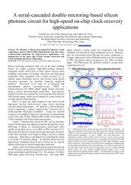
IEEE TRANSACTIONS ON CIRCUITS AND SYSTEMS—I: FUNDAMENTAL THEORY AND APPLICATIONS, VOL. 45, NO. 2, FEBRUARY 1998 121<strong>Gabor</strong>-<strong>Type</strong> <strong>Filter<strong>in</strong>g</strong> <strong>in</strong> <strong>Space</strong> <strong>and</strong> <strong>Time</strong>with Cellular Neural NetworksBertram E. Shi, Member, IEEEAbstract— <strong>Gabor</strong> filters are preprocess<strong>in</strong>g stages <strong>in</strong> imageprocess<strong>in</strong>g<strong>and</strong> computer-vision applications. One drawback isthat they are computationally <strong>in</strong>tensive on a digital computer.This paper describes the design <strong>of</strong> cellular neural networks(CNN’s) which compute the outputs <strong>of</strong> filters similar to <strong>Gabor</strong>filters. Analog VLSI implementations <strong>of</strong> these CNN’s might eventuallyrelieve the computational bottleneck associated with <strong>Gabor</strong>filter<strong>in</strong>g image-process<strong>in</strong>g algorithms. The CNN’s compute boththe real <strong>and</strong> imag<strong>in</strong>ary parts <strong>of</strong> the filter outputs simultaneously,which is an important feature <strong>in</strong> apply<strong>in</strong>g them <strong>in</strong> algorithmsutiliz<strong>in</strong>g the phase <strong>of</strong> the <strong>Gabor</strong> output.Index Terms—Analog circuits, cellular neural networks, filter<strong>in</strong>g,image process<strong>in</strong>g, neural networks.I. INTRODUCTIONGABOR filters [1] have been used as preprocessors fordifferent tasks <strong>in</strong> computer vision <strong>and</strong> image process<strong>in</strong>g.These approaches to image process<strong>in</strong>g <strong>and</strong> computer visionhave been motivated partially by the discovery that the responses<strong>of</strong> orientation selective cells <strong>in</strong> the visual cortex canbe modeled us<strong>in</strong>g <strong>Gabor</strong> filters [2], [3]. Because image velocitycan be considered as an orientation <strong>in</strong> the space–time doma<strong>in</strong>,three-dimensional (3-D) <strong>Gabor</strong> filters have been used to modelcortical cells’ velocity <strong>and</strong> directional sensitivity [4]. Initialevidence <strong>in</strong>dicates that approaches based upon <strong>Gabor</strong> filter<strong>in</strong>gcan outperform previously developed approaches [5].One drawback <strong>of</strong> <strong>Gabor</strong> filter<strong>in</strong>g approaches is that they arecomputationally <strong>in</strong>tensive. Here we describe how to implementfilters similar to the <strong>Gabor</strong> filter us<strong>in</strong>g cellular neural networks(CNN’s) [6]–[8]. The advantage <strong>of</strong> CNN’s is that they can beimplemented <strong>in</strong> analog VLSI alongside photosensors whichsense the image [9]–[11]. The filter outputs can be computed<strong>in</strong> less time than required by serial digital computer implementations<strong>and</strong> be read <strong>of</strong>f the chip directly, reliev<strong>in</strong>g thecomputational bottleneck <strong>of</strong> preprocess<strong>in</strong>g with <strong>Gabor</strong> filters.The rema<strong>in</strong>der <strong>of</strong> Section I reviews <strong>Gabor</strong> filters <strong>and</strong> def<strong>in</strong>esthe class <strong>of</strong> “<strong>Gabor</strong>-type” filters which we believe capture theimportant properties <strong>of</strong> <strong>Gabor</strong> filters exploited by many imageprocess<strong>in</strong>g<strong>and</strong> computer-vision applications. It concludes witha short review <strong>of</strong> previous related work. Section II shows thatany low-pass spatial filter implemented on a CNN can betransformed <strong>in</strong>to a correspond<strong>in</strong>g <strong>Gabor</strong>-type filter <strong>and</strong> givesManuscript received September 11, 1996; revised February 26, 1997. Thiswork was supported by the Hong Kong Research Grants Council under GrantHKUST675/9E. This paper was recommended by Associate Editor J. P<strong>in</strong>edade-Gyvez.The author is with the <strong>Department</strong> <strong>of</strong> Electrical <strong>and</strong> <strong>Electronic</strong> Eng<strong>in</strong>eer<strong>in</strong>g,Hong Kong University <strong>of</strong> Science <strong>and</strong> Technology, Kowloon, Hong Kong.Publisher Item Identifier S 1057-7122(98)00889-7.several illustrative examples <strong>of</strong> the types <strong>of</strong> filters which canbe achieved on CNN’s. Section III extends the results to spatio–temporalfilters. F<strong>in</strong>ally, Section IV summarizes our results<strong>and</strong> outl<strong>in</strong>es ongo<strong>in</strong>g research <strong>in</strong> design<strong>in</strong>g <strong>and</strong> fabricat<strong>in</strong>ganalog VLSI chips implement<strong>in</strong>g these CNN’s <strong>and</strong> apply<strong>in</strong>gthem <strong>in</strong> computer vision.In the follow<strong>in</strong>g, small letters denote space <strong>and</strong> time waveforms,e.g., , ,or where represents cont<strong>in</strong>uousspace, represents discrete space, <strong>and</strong> represents cont<strong>in</strong>uoustime. Capital letters denote Fourier transforms. Transforms <strong>of</strong>a cont<strong>in</strong>uous waveform or will be written asor , while transforms <strong>of</strong> a discrete waveform willbe written as .A. <strong>Gabor</strong> Filters<strong>Gabor</strong> filters exist for signals <strong>of</strong> arbitrary dimension wherean -dimensional signal is def<strong>in</strong>ed to be a mapp<strong>in</strong>g fromto or . For one-dimensional (1-D) signals, the impulseresponse <strong>of</strong> a <strong>Gabor</strong> filter is a complex exponentialfunction modulated by a Gaussianwhere is the angular frequency <strong>of</strong> the complex exponential<strong>and</strong> is the st<strong>and</strong>ard deviation <strong>of</strong> the Gaussian. Fig. 1(a)<strong>and</strong> (b) plot the real <strong>and</strong> imag<strong>in</strong>ary parts <strong>of</strong> (1). Although theimpulse response is def<strong>in</strong>ed for cont<strong>in</strong>uous , s<strong>in</strong>ce the <strong>Gabor</strong>typefilters implemented by CNN’s are <strong>in</strong>herently discretespace, we plot the impulse responses at discrete <strong>in</strong>teger values<strong>of</strong> to facilitate comparison with later results.By the Fourier shift theorem, the frequency response <strong>of</strong> a<strong>Gabor</strong> filter is a Gaussian function centered at :The <strong>Gabor</strong> filter is a b<strong>and</strong>pass filter tuned to frequencies near[see Fig. 1(c)]. Generaliz<strong>in</strong>g to -dimensional signals, theconvolution kernel <strong>and</strong> frequency response arewhere , the covariance matrix is positive(1)1057–7122/98$10.00 © 1998 IEEE
122 IEEE TRANSACTIONS ON CIRCUITS AND SYSTEMS—I: FUNDAMENTAL THEORY AND APPLICATIONS, VOL. 45, NO. 2, FEBRUARY 1998(a) (b) (c)(d) (e) (f)Fig. 1.(g) (h) (i)A comparison <strong>of</strong> the impulse <strong>and</strong> frequency responses <strong>of</strong> the 1-D <strong>Gabor</strong> filter <strong>and</strong> <strong>Gabor</strong>-type filters implementable on a CNN. The filter parametershave been chosen so that the squared errors between the impulse responses are m<strong>in</strong>imized. (a)–(b) The real <strong>and</strong> imag<strong>in</strong>ary parts <strong>of</strong> the impulse response <strong>of</strong>a <strong>Gabor</strong> filter with = 3:32 <strong>and</strong> !xo =0:93 are s<strong>in</strong>e <strong>and</strong> cos<strong>in</strong>e functions modulated by a Gaussian (dotted l<strong>in</strong>e). The responses are plotted at <strong>in</strong>tegervalues <strong>of</strong> x to facilitate comparison with the other plots. (c) The frequency response <strong>of</strong> the <strong>Gabor</strong> filter is a Gaussian centered at !xo. (d)–(e) The real <strong>and</strong>imag<strong>in</strong>ary parts <strong>of</strong> the impulse response <strong>of</strong> the <strong>Gabor</strong>-type filter <strong>in</strong> Example 1 for =0:3<strong>and</strong> !xo =0:93 are s<strong>in</strong>e <strong>and</strong> cos<strong>in</strong>e functions modulated bya function which decays exponentially away from the orig<strong>in</strong> (dotted l<strong>in</strong>e). (f) The frequency response <strong>of</strong> the filter <strong>in</strong> Example 1 is the Fourier transform<strong>of</strong> the modulat<strong>in</strong>g function shifted to !xo. S<strong>in</strong>ce the filter is def<strong>in</strong>ed for discrete space, the frequency response is periodic with period 2. (g)–(h) Thereal <strong>and</strong> imag<strong>in</strong>ary parts <strong>of</strong> the <strong>Gabor</strong>-type filter <strong>in</strong> Example 2 for =0:352 <strong>and</strong> !xo =0:93 more closely approximate the <strong>Gabor</strong>. (i) The frequencyresponse <strong>of</strong> the filter <strong>in</strong> Example 2 is approximately Gaussian, but is flatter at the peak at !xo.def<strong>in</strong>ite, <strong>and</strong>. The covariance matrix is <strong>of</strong>tenchosen to be a scalar multiple <strong>of</strong> the identity matrix.Two-dimensional (2-D) <strong>Gabor</strong> filters are orientation selective<strong>and</strong> have been used to model receptive fields <strong>of</strong> orientationselective neurons <strong>in</strong> the visual cortex. For example, the <strong>Gabor</strong>filter with impulse responseis tuned to spatial frequencyThis filter respondsmaximally to edges which are oriented at an anglewhere is def<strong>in</strong>ed to be the angle betweenthe horizontal axis <strong>and</strong> the l<strong>in</strong>e perpendicular to theedge (see Fig. 2). 2-D <strong>Gabor</strong> filters have found applications<strong>in</strong> computer-vision algorithms for stereo vision [12]–[18],b<strong>in</strong>ocular vergence control [19], texture segmentation [20],<strong>and</strong> face recognition [21].Three–dimensional spatio–temporal <strong>Gabor</strong> filters have beenused for image-motion analysis [22]–[24]. Image motion canbe characterized as an orientation <strong>in</strong> the space–time doma<strong>in</strong>[4]. The energy spectrum <strong>of</strong> a 1-D image undergo<strong>in</strong>g uniformtranslation at velocity is nonzero only along the l<strong>in</strong>e. For 2-D images translat<strong>in</strong>g with velocity ,the spectrum is nonzero only along the plane. A spatio–temporal b<strong>and</strong>pass filter tuned to frequencycan be considered to be tuned to the velocity
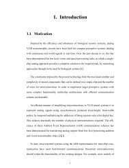
SHI: GABOR-TYPE FILTERING IN SPACE AND TIME WITH CELLULAR NEURAL NETWORKS 123filter’s output, its magnitude <strong>and</strong> phase are(a)The phase <strong>of</strong> the output at a given pixel is related to thelocation <strong>of</strong> edges <strong>and</strong> other features <strong>in</strong> the <strong>in</strong>put image nearthat pixel. Translat<strong>in</strong>g the image <strong>in</strong>put results <strong>in</strong> a phase shift <strong>in</strong>the <strong>Gabor</strong> output at a given pixel. This property has motivatedthe development <strong>of</strong> “phase-based” approaches to stereo-vision<strong>and</strong> image-motion analysis. Phase differences between the<strong>Gabor</strong> filter outputs from two stereo images can be used toestimate disparity [12]–[18] <strong>and</strong> control b<strong>in</strong>ocular vergence <strong>in</strong>active-vision systems [19]. Fleet [24] showed that the temporalvariation <strong>of</strong> phase is a robust <strong>in</strong>dicator <strong>of</strong> the local imagevelocity. Barron et al.’s comparison [5] <strong>of</strong> algorithms foroptical-flow estimation <strong>in</strong>dicates that Fleet’s algorithm us<strong>in</strong>g<strong>Gabor</strong> phase is the most accurate among those tested. Manyphase-based algorithms use the amplitude as a confidencemeasure for the reliability <strong>of</strong> the phase measurement.B. <strong>Gabor</strong>-<strong>Type</strong> FiltersWe extend <strong>Gabor</strong> filters to <strong>Gabor</strong>-type filters by allow<strong>in</strong>gmodulat<strong>in</strong>g functions other than the Gaussian. Formally, def<strong>in</strong>ea filter to be <strong>Gabor</strong>-type if its impulse response can beexpressed as a complex exponential modulated by a real valuedenvelope , which is the impulse response <strong>of</strong> a low-passfilterAll <strong>Gabor</strong> filters are <strong>Gabor</strong>-type. The frequency response<strong>of</strong> a <strong>Gabor</strong>-type filter is equal to the Fourier transform<strong>of</strong> the modulat<strong>in</strong>g function shifted to :(b)Fig. 2. The (a) real <strong>and</strong> (b) imag<strong>in</strong>ary parts <strong>of</strong> the impulse response <strong>of</strong> a2-D <strong>Gabor</strong> filter which is tuned to the orientation = =4.Spatio–temporal filter<strong>in</strong>g approaches to estimat<strong>in</strong>g the opticalflow <strong>of</strong>ten compare the outputs <strong>of</strong> filters tuned to differentregions <strong>in</strong> the spatio–temporal frequency doma<strong>in</strong>. The opticalflow is the projection <strong>of</strong> the 3-D motion vector field result<strong>in</strong>gfrom relative motion between a camera <strong>and</strong> its environmentto a 2-D motion vector field <strong>in</strong> the image plane. Estimation <strong>of</strong>the optical flow is one <strong>of</strong> the first steps <strong>in</strong> many algorithmswhich extract the shape <strong>of</strong> surfaces be<strong>in</strong>g imaged by a mov<strong>in</strong>gcamera [25].For computer-vision applications, the output <strong>of</strong> a <strong>Gabor</strong>filter is <strong>of</strong>ten expressed <strong>in</strong> terms <strong>of</strong> its magnitude <strong>and</strong> phase. If<strong>and</strong> are the real <strong>and</strong> imag<strong>in</strong>ary parts <strong>of</strong> a <strong>Gabor</strong><strong>Gabor</strong>-type filters do not necessarily optimize the uncerta<strong>in</strong>tyrelation between the resolution <strong>in</strong> space <strong>and</strong> spatial frequency,a commonly cited advantage <strong>of</strong> <strong>Gabor</strong> filters result<strong>in</strong>g fromtheir Gaussian modulat<strong>in</strong>g function. However, they can bedesigned to satisfy the requirements <strong>of</strong> filters used for phasebasedalgorithms <strong>in</strong> computer vision. In their phase-baseddisparity study, Westelius et al. [18] exam<strong>in</strong>ed the use <strong>of</strong> filtersother than the <strong>Gabor</strong> <strong>and</strong> found that the overall performance<strong>of</strong> their algorithm “was not critically dependent upon thetype <strong>of</strong> disparity filter used.” They identified several desirableproperties for 1-D filters used to compute phase.1) The filter has no dc component.2) The filter is sensitive to positive frequencies only.3) The filter is <strong>in</strong>sensitive to s<strong>in</strong>gular po<strong>in</strong>ts.4) The phase <strong>of</strong> the impulse response does not wrap around(i.e., exceed ).5) The filter has small spatial support.6) The phase <strong>of</strong> the impulse response is monotonous.
124 IEEE TRANSACTIONS ON CIRCUITS AND SYSTEMS—I: FUNDAMENTAL THEORY AND APPLICATIONS, VOL. 45, NO. 2, FEBRUARY 1998In order for a <strong>Gabor</strong>-type filter to possess the first threeproperties, its b<strong>and</strong>width should be small <strong>in</strong> comparison withthe center frequency , which we assume to be positive. Ifis identically zero outside the range ,the response <strong>of</strong> the filter to dc <strong>and</strong> negative frequenciesis identically zero. In general, the frequency response <strong>of</strong> a<strong>Gabor</strong>-type filter may have <strong>in</strong>f<strong>in</strong>ite support. However, because<strong>of</strong> the low-pass nature <strong>of</strong> , it is possible to make themaximum response to dc <strong>and</strong> negative frequencies smallerthan any fixed positive threshold by decreas<strong>in</strong>g the b<strong>and</strong>widthsufficiently. In addition, even if the dc response is not zero,an extra process<strong>in</strong>g step can easily be added to remove thedc component. Westelius et al. po<strong>in</strong>t out that the sensitivity tos<strong>in</strong>gular po<strong>in</strong>ts also decreases with b<strong>and</strong>width.On the other h<strong>and</strong>, the fourth <strong>and</strong> fifth properties imply alarge b<strong>and</strong>width s<strong>in</strong>ce they constra<strong>in</strong> the width <strong>of</strong> the impulseresponse. The fourth requirement is satisfied by <strong>Gabor</strong>-typefilters if is identically zero outside the range. For filters which do not satisfy this condition, theeffects <strong>of</strong> phase wraparound can be m<strong>in</strong>imized by ensur<strong>in</strong>gthat width <strong>of</strong> is small enough that the impulse responseis close to zero outside this range. In general, the fourth <strong>and</strong>fifth properties are less critical than the first three. Westeliuset al. state that the fourth requirement is “desirable, but notabsolutely necessary.” The fifth property, small spatial support,was <strong>in</strong>cluded s<strong>in</strong>ce it determ<strong>in</strong>es the computational cost <strong>of</strong>the filter. However, one goal <strong>of</strong> this paper is to decreasethe computational cost <strong>of</strong> <strong>Gabor</strong>-type filters by enabl<strong>in</strong>g theirimplementation <strong>in</strong> analog VLSI.The sixth property can be satisfied by <strong>Gabor</strong>-type filterswith both large <strong>and</strong> small b<strong>and</strong>widths. Any <strong>Gabor</strong>-type filter<strong>in</strong> which is strictly positive satisfies this property. Forfilters that do not satisfy this property, the effect <strong>of</strong> phasenonmontonicity can be alleviated by ensur<strong>in</strong>g that the absolutevalue <strong>of</strong> the low-pass envelope is small when it changes sign.In summary, a <strong>Gabor</strong>-type filter can be used effectively <strong>in</strong>phase-based disparity estimation if its b<strong>and</strong>width is chosento be small enough <strong>and</strong> if the modulat<strong>in</strong>g function is strictlypositive or at least positive over the region where its magnitudeis significant. Although Westelius et al.’s study was conf<strong>in</strong>edto disparity estimation, we expect that the properties theyhave identified to be applicable to filters for other phase-basedalgorithms, such as for image-motion analysis. For example,the <strong>Gabor</strong>-type filter <strong>in</strong> Example 1 has been used <strong>in</strong> a phasebasedalgorithm for extract<strong>in</strong>g time-to-contact from a mov<strong>in</strong>gimage taken by a camera translat<strong>in</strong>g toward a planar surface[26].C. Previous WorkRaffo has demonstrated that a resistive network similar tothat shown <strong>in</strong> Fig. 5 followed by an additional process<strong>in</strong>g stagecan implement a real valued <strong>Gabor</strong>-type filter with arbitraryphase [28]. In particular, for 1-D signals the convolution kernelhas the formwhere can be chosen arbitrarily. For , this is thereal part <strong>of</strong> convolution kernel implemented by the networkdescribed <strong>in</strong> Example 1. For , it is the imag<strong>in</strong>ary part.In some ways, the two networks are similar <strong>in</strong> complexity<strong>and</strong> capability. Raffo’s network requires connections to secondnearest neighbors. Although the network <strong>of</strong> Example 1 requiresonly nearest neighbor <strong>in</strong>terconnections, each pixel requirestwo nodes. The network <strong>of</strong> Example 1 computes both real<strong>and</strong> imag<strong>in</strong>ary parts <strong>of</strong> the <strong>Gabor</strong>-type outputs simultaneously,but this could be done by Raffo’s network by add<strong>in</strong>g twoadditional process<strong>in</strong>g stages rather than one. The arbitraryphase achieved by Raffo’s network could be obta<strong>in</strong>ed bya l<strong>in</strong>ear comb<strong>in</strong>ation <strong>of</strong> the two outputs <strong>of</strong> the network <strong>of</strong>Example 1.One advantage <strong>of</strong> the network <strong>of</strong> Example 1 is that thedependency <strong>of</strong> the conductances <strong>and</strong> transconductances onthe parameters <strong>and</strong> , which determ<strong>in</strong>e the shape <strong>of</strong>the convolution kernel, are simpler than for Raffo’s network.For example, the resistor between nearest neighbor nodes forRaffo’s network has conductancewhereThe transconductances <strong>in</strong> the second process<strong>in</strong>g stage are alsocomplex functions <strong>of</strong> , , <strong>and</strong> . On the other h<strong>and</strong>,for the network <strong>of</strong> Example 1 is uniquely specified bythe ratio <strong>of</strong> the conductances <strong>and</strong> . In addition, if. The methodologypresented here can also be used to implement a wide class <strong>of</strong><strong>Gabor</strong>-type filters, <strong>of</strong> which Example 1 is only one example.In addition, this paper discusses not only spatial filter<strong>in</strong>g,but also spatio–temporal filter<strong>in</strong>g. Previous work <strong>in</strong> this area<strong>in</strong>cludes Delbruck’s successful VLSI implementation <strong>of</strong> avelocity-sensitive filter us<strong>in</strong>g a delay l<strong>in</strong>e consist<strong>in</strong>g <strong>of</strong> acascade <strong>of</strong> first-order filter stages [29]. Unlike the <strong>Gabor</strong>-typefilters proposed here, the spatio–temporal filters implementedby the delay l<strong>in</strong>e are not separable <strong>in</strong> space <strong>and</strong> time likethe <strong>Gabor</strong> filters. <strong>Space</strong>–time separability can be exploited <strong>in</strong>comput<strong>in</strong>g the optical flow [23]. In addition, the delay l<strong>in</strong>edoes not generate the complex valued filter output critical tophase-based algorithms.II. SPATIAL FILTERSThis section <strong>in</strong>troduces CNN architectures for <strong>Gabor</strong>-typespatial filter<strong>in</strong>g. For simplicity, we <strong>in</strong>troduce architectures for1-D images before generaliz<strong>in</strong>g to two dimensions.A. 1-D ImagesThe CNN is a neural-network architecture consist<strong>in</strong>g <strong>of</strong>an array <strong>of</strong> neurons, called “cells.” Each cell is a first-ordercont<strong>in</strong>uous-time dynamical system. To filter an -pixel 1-Dimage, where , we use a 1-DCNN array <strong>of</strong> cells where the state at the th cellsatisfies(2)
SHI: GABOR-TYPE FILTERING IN SPACE AND TIME WITH CELLULAR NEURAL NETWORKS 125The dot denotes differentiation with respect to time. The<strong>and</strong> are complex coefficients called thefeedback <strong>and</strong> feedforward clon<strong>in</strong>g templates <strong>and</strong> is def<strong>in</strong>edto be the connection radius. We represent the feedback clon<strong>in</strong>gtemplate us<strong>in</strong>g amatrix where the center elementequals . For example, for , the clon<strong>in</strong>g template matrixisThis CNN equation is slightly different than that presented<strong>in</strong> [6] <strong>and</strong> [7]. The key differences are that here the state iscomplex rather than real <strong>and</strong> the bias <strong>and</strong> nonl<strong>in</strong>earity areexcluded. However, (2) can be considered to be a special case<strong>of</strong> a two-layer CNN as presented <strong>in</strong> [6], where: 1) the cells <strong>in</strong>the first layer represent the real parts <strong>of</strong> the complex valuedstate; 2) the cells <strong>in</strong> the second layer represent the imag<strong>in</strong>arypart; 3) the bias terms are identically zero; <strong>and</strong> 4) the outputalways operates <strong>in</strong> the l<strong>in</strong>ear region <strong>of</strong> the output nonl<strong>in</strong>earity.Thus, the hardware complexity <strong>of</strong> the CNN def<strong>in</strong>ed here iscomparable to that <strong>of</strong> a two-layer CNN.S<strong>in</strong>ce the dynamics <strong>of</strong> the CNN <strong>in</strong> (2) are purely l<strong>in</strong>ear, thestability <strong>of</strong> any template can be evaluated theoretically [30]. Ifthe CNN is stable, then for an <strong>in</strong>put which is constant <strong>in</strong> time,the state settles to a unique equilibrium po<strong>in</strong>t which isa spatially filtered version <strong>of</strong> the <strong>in</strong>put . The steady-statevalue <strong>of</strong> is the output <strong>of</strong> the “computation” performed bythis CNN. The length <strong>of</strong> the transient is the time required toperform the computation. Assume that the CNN array consists<strong>of</strong> an <strong>in</strong>f<strong>in</strong>ite number <strong>of</strong> cells <strong>in</strong>dexed by .Def<strong>in</strong>e the discrete-space Fourier transforms <strong>of</strong> the <strong>in</strong>put <strong>and</strong>output to bedesign<strong>in</strong>g CNN’s for low-pass filter<strong>in</strong>g <strong>in</strong> [31]. The follow<strong>in</strong>gfocuses on mapp<strong>in</strong>g a template implement<strong>in</strong>g a low-pass filterto the template which implements the correspond<strong>in</strong>g <strong>Gabor</strong>typefilter.Suppose that the clon<strong>in</strong>g templates <strong>and</strong> are chosen sothat the correspond<strong>in</strong>g CNN implements a low-pass filter withfrequency response . By shift<strong>in</strong>g such that itis centered around , we obta<strong>in</strong> the frequency response <strong>of</strong>the correspond<strong>in</strong>g <strong>Gabor</strong>-type filter tuned to :This filter can be implemented by a CNN with the same feedforwardclon<strong>in</strong>g template <strong>and</strong> the complex valued feedbackclon<strong>in</strong>g templateUs<strong>in</strong>g the approach <strong>in</strong> [30], it can be shown that if the orig<strong>in</strong>allow-pass filter template is stable, then the correspond<strong>in</strong>g<strong>Gabor</strong>-type template is also stable.Example 1: Consider the low-pass filter implemented bythe CNN with clon<strong>in</strong>g templateswhere . Substitut<strong>in</strong>g <strong>in</strong>to (2)(4)The frequency response <strong>of</strong> the spatial filter is(3)Assum<strong>in</strong>g both <strong>and</strong> are real, the l<strong>in</strong>ear resistive grid[32] <strong>in</strong> Fig. 3(a) implements this CNN. At steady state,is a low-pass filtered version <strong>of</strong> . Fig. 3(b) <strong>and</strong> (c) plotsthe impulse <strong>and</strong> frequency responses <strong>of</strong> the filter which aregiven by [33]:A similar result us<strong>in</strong>g the discrete Fourier transform (DFT)holds for f<strong>in</strong>ite arrays with periodic boundary conditions wherethe cells at the ends <strong>of</strong> the array are considered to be nearestneighbors. With other boundary conditions, the analysis herewill be approximate, but for stable filters the effect <strong>of</strong> theboundary conditions decays as the distance from the boundary<strong>in</strong>creases. By chang<strong>in</strong>g the values <strong>of</strong> the clon<strong>in</strong>g templatecoefficients, different filters, e.g., low-pass, b<strong>and</strong>pass, <strong>and</strong>high-pass, can be constructed. S<strong>in</strong>ce the CNN consists <strong>of</strong> adiscrete array <strong>of</strong> cells, the filters are def<strong>in</strong>ed only for discretespace<strong>in</strong>put.For every low-pass filter implementable on a CNN, the<strong>Gabor</strong>-type filter obta<strong>in</strong>ed by multiply<strong>in</strong>g the impulse response<strong>of</strong> that low-pass filter by a complex exponential is also implementableon a CNN. Crounse <strong>and</strong> Chua describe methods forwhere. This system is a discreteapproximation to a cont<strong>in</strong>uous space system with impulse <strong>and</strong>frequency responseswhere the subscript emphasizes that the function is def<strong>in</strong>edon cont<strong>in</strong>uous space. The width <strong>of</strong> the impulse response<strong>in</strong>creases l<strong>in</strong>early with . The approximation improves asdecreases.By (4), the correspond<strong>in</strong>g <strong>Gabor</strong> filter [34] is implementedby the CNN with templates(5)(6)
126 IEEE TRANSACTIONS ON CIRCUITS AND SYSTEMS—I: FUNDAMENTAL THEORY AND APPLICATIONS, VOL. 45, NO. 2, FEBRUARY 1998(a)(b)(c)Fig. 3. (a) This resistive grid implements the low-pass filter<strong>in</strong>g CNN <strong>of</strong> Example 1. The resistor labels denote conductances. The (b) impulse <strong>and</strong> (c)frequency responses <strong>of</strong> the filter for = 0:3 confirm the expected low-pass behavior.Fig. 4. A circuit implementation <strong>of</strong> two cells <strong>of</strong> a CNN array which implements the <strong>Gabor</strong>-type filter correspond<strong>in</strong>g to the resistive grid discussed <strong>in</strong> Example1. Resistor labels denote conductances. Trapezoidal blocks represent transconductance amplifiers labeled by their ga<strong>in</strong>s.Its impulse <strong>and</strong> frequency responses, plotted <strong>in</strong> Fig. 1(d) <strong>and</strong>(e) arecomplex state variable has been replaced by two real valuedstate variablesFor a circuit implementation <strong>of</strong> this network, the complexvalued state is represented by the voltages across twocapacitors represent<strong>in</strong>g its real <strong>and</strong> imag<strong>in</strong>ary parts <strong>and</strong>. Substitut<strong>in</strong>g (6) <strong>in</strong>to (2) <strong>and</strong> separat<strong>in</strong>g the real <strong>and</strong>imag<strong>in</strong>ary parts, we can express the time evolution <strong>of</strong> thecomplex valued state <strong>in</strong> (2) as an equivalent system where the(7)
SHI: GABOR-TYPE FILTERING IN SPACE AND TIME WITH CELLULAR NEURAL NETWORKS 127Fig. 5. This resistive network better approximat<strong>in</strong>g Gaussian filter<strong>in</strong>g adds negative resistance connections to second nearest neighbors. Only the fullconnections for node n are shown. The resistor labels denote conductances.The circuit <strong>in</strong> Fig. 4 implements two cells <strong>of</strong> the CNN <strong>and</strong>their <strong>in</strong>terconnections with their nearest neighbors. In thefollow<strong>in</strong>g, we refer to each circuit node by its labeled nodalvoltage. The voltages across each pair <strong>of</strong> vertically alignedcapacitors represent the real <strong>and</strong> imag<strong>in</strong>ary parts <strong>of</strong> the state<strong>of</strong> a cell. The resistances <strong>and</strong> transconductance amplifiersimplement the <strong>in</strong>terconnection between cells. The <strong>in</strong>put to thenetwork is provided by current sources which supply currentsproportional to the <strong>in</strong>put image <strong>in</strong>tensity. By writ<strong>in</strong>g KCL atnodes <strong>and</strong> <strong>and</strong> assum<strong>in</strong>g a unit capacitance, onecan verify that the time evolution <strong>of</strong> satisfies the topequation <strong>in</strong> (7) <strong>and</strong> that satisfies the bottom equation.The entire CNN array can be constructed by replicat<strong>in</strong>g thiscircuit to add more cells <strong>and</strong> connections. At steady state,the voltages across the lower capacitors are the result <strong>of</strong>convolv<strong>in</strong>g the spatial distribution <strong>of</strong> the <strong>in</strong>put currents withthe real part <strong>of</strong> . The voltages across the upper capacitorscorrespond to convolv<strong>in</strong>g with the imag<strong>in</strong>ary part. This mixedtransconductance amplifier <strong>and</strong> resistor implementation canbe proven to be more robust to parameter variations thanimplementations based on either resistors or transconductanceamplifiers alone [35].The circuit implementation also gives good <strong>in</strong>tuitive underst<strong>and</strong><strong>in</strong>g<strong>of</strong> the CNN’s operation. Assume that the <strong>in</strong>putimage is an impulse at pixel . In the circuit, this correspondsto sett<strong>in</strong>g the current source to amps <strong>and</strong> sett<strong>in</strong>gthe rema<strong>in</strong><strong>in</strong>g current sources to zero. If the ga<strong>in</strong>s <strong>and</strong> conductanceswere chosen so that <strong>and</strong> , thenthe steady-state voltages across the lower capacitors wouldfollow the spatial distribution shown <strong>in</strong> Fig. 1(d) where thecenter peak occurs at cell <strong>and</strong> the voltages across the uppercapacitors would follow the distribution shown <strong>in</strong> Fig. 1(e).To see how this would arise <strong>in</strong> the circuit, consider thecurrent supplied by the source . Part <strong>of</strong> the currentflows through the conductance (which is positive) push<strong>in</strong>gthe voltage positive. As this voltage <strong>in</strong>creases, the tworesistors with conductancecause a smooth<strong>in</strong>geffect which pulls the voltages <strong>and</strong> uptoward . Current also flows through the diagonal resistorwith conductance pull<strong>in</strong>g positiveas well. At the same time, the transconductance amplifierwith <strong>in</strong>put draws current from node push<strong>in</strong>gnegative. The larger , the more the voltages atnodes <strong>and</strong> are pushed negative <strong>and</strong> positive.On the other h<strong>and</strong>, the larger , the greater the smooth<strong>in</strong>gbetween nodes. Thus, the larger the ratiothe higher the spatial frequency at which the impulseresponse oscillates. This is consistent with our theoreticalpredictions s<strong>in</strong>ce tan <strong>in</strong>creases with .Example 2: Based upon Kobayashi et al.’s resistor networkfor Gaussian filter<strong>in</strong>g [36], it is possible to design a CNNwhich implements a filter with an impulse response which iscloser to the <strong>Gabor</strong>, albeit at the price <strong>of</strong> <strong>in</strong>creased complexity.For 1-D images, the resistor network <strong>in</strong> Fig. 5 smooths the<strong>in</strong>put current distribution with an approximately Gaussianconvolution kernel. The correspond<strong>in</strong>g CNN clon<strong>in</strong>g templatesareThe filter implemented by this network is a discrete approximationto a cont<strong>in</strong>uous space filter with impulse <strong>and</strong> frequencyresponses given by [37]The width <strong>of</strong> the impulse response <strong>in</strong>creases l<strong>in</strong>early with .The approximation improves as decreases.The template for the correspond<strong>in</strong>g <strong>Gabor</strong>-type filter isFig. 1(g)–(i) plots the impulse <strong>and</strong> frequency responses <strong>of</strong> thisfilter.To compare how well the filters <strong>in</strong> the preced<strong>in</strong>g examplesapproximate <strong>Gabor</strong> filters, we def<strong>in</strong>e the normalized squarederror (NSE) to be the total energy <strong>in</strong> the difference betweenthe <strong>Gabor</strong> impulse response <strong>and</strong> the impulse response <strong>of</strong> thecont<strong>in</strong>uous space filter approximated by the CNN filter dividedby the total energy <strong>in</strong> the <strong>Gabor</strong> impulse responsewhere is the <strong>Gabor</strong> impulse response <strong>in</strong> (1) <strong>and</strong> isgiven either by (5) or (8). The frequencies <strong>of</strong> the complexexponentials <strong>in</strong> the <strong>Gabor</strong> <strong>and</strong> <strong>Gabor</strong>-type filters are(8)
128 IEEE TRANSACTIONS ON CIRCUITS AND SYSTEMS—I: FUNDAMENTAL THEORY AND APPLICATIONS, VOL. 45, NO. 2, FEBRUARY 1998chosen to be identical. The results <strong>of</strong> analyz<strong>in</strong>g the discretespacefilters will be more complex, but very similar to theresults here, especially as <strong>and</strong> approach zero.Us<strong>in</strong>g the fact that, it can be shown thatthe error is <strong>in</strong>dependent <strong>of</strong> <strong>and</strong> depends only upon thedifference between the Gaussian envelope <strong>of</strong> the <strong>Gabor</strong> filter<strong>and</strong> the low-pass envelope <strong>of</strong> the <strong>Gabor</strong>-type filter. Forthe filter <strong>in</strong> Example 1, the m<strong>in</strong>imum error <strong>of</strong> 15 dB isachieved forTABLE ICOMPARISON OF PHASE MEASUREMENT PROPERTIESOF GABOR AND GABOR-TYPE FILTERSFor the filter <strong>in</strong> Example 2, the m<strong>in</strong>imum error <strong>of</strong>achieved for21 dB isThe values <strong>of</strong> <strong>and</strong> have been estimated numerically.Simulation results <strong>in</strong> Fig. 1 where the parameters chosenm<strong>in</strong>imize the NSE provide visual confirmation that the impulse<strong>and</strong> frequency responses <strong>of</strong> the filter <strong>in</strong> Example 2 are closerto the <strong>Gabor</strong> filter’s than are those <strong>of</strong> the filter <strong>in</strong> Example 1.To compare the three filters with respect to the desirableproperties for comput<strong>in</strong>g phase discussed <strong>in</strong> Section I-B, wedef<strong>in</strong>e the follow<strong>in</strong>g criteria. The criteria are based upon theassumption that the <strong>in</strong>put image is white.Negative Frequency Rejection (NFR): This is the ratio betweenthe energy <strong>in</strong> the output due to positive frequencies <strong>in</strong>the <strong>in</strong>put <strong>and</strong> the energy due to negative frequencies. Ifis the frequency response <strong>of</strong> the filter, thenDC Rejection (DCR): This is a measure <strong>of</strong> the extent towhich the dc component is suppressed compared with the peakresponse. If is the frequency response <strong>of</strong> the filterPhase Wraparound Rejection (PWR): The output at a givenpixel can be considered as the sum <strong>of</strong> two components: thefirst (desired) component due to convolv<strong>in</strong>g the image with thepart <strong>of</strong> the impulse response where the phase varies fromto <strong>and</strong> the second (undesired) component due to convolv<strong>in</strong>gthe <strong>in</strong>put image with the part <strong>of</strong> the impulse response wherethe phase has wrapped around. S<strong>in</strong>ce we assume the image<strong>in</strong>put is white, these two components are uncorrelated. Wedef<strong>in</strong>e the PWR to be the ratio <strong>of</strong> their energies. If is theimpulse response <strong>of</strong> the filter, thenwell as whether or not the phase <strong>of</strong> the impulse responseis monotonous. The results were estimated numerically us<strong>in</strong>gthe same filter parameters used to generate the plots. S<strong>in</strong>cethe parameters were chosen to m<strong>in</strong>imize the energy <strong>in</strong> thedifference between the filter impulse responses, their spatialsupport is similar. S<strong>in</strong>ce the PWR is def<strong>in</strong>ed <strong>in</strong> terms <strong>of</strong> theenergy <strong>in</strong> the filters, their PWR is also similar. However, thereare large differences between the NFR <strong>and</strong> DCR. As can beseen from Table I as well as the plots <strong>in</strong> Fig. 1, the NFR <strong>and</strong>DCR is largest for the <strong>Gabor</strong> filter <strong>and</strong> smallest for the filter<strong>in</strong> Example 1. The rejection can be improved at the cost <strong>of</strong>decreased PWR by decreas<strong>in</strong>g the b<strong>and</strong>width <strong>of</strong> the filters.Only the filter <strong>in</strong> Example 2 does not have monotonous phase,s<strong>in</strong>ce its low-pass modulat<strong>in</strong>g function is not strictly positive.Although the degree to which the filters exhibit the propertiesdescribed <strong>in</strong> Section I-B varies, we would expect any <strong>of</strong> thefilters to be effective <strong>in</strong> phase-based algorithms because thesealgorithms have been found to be fairly <strong>in</strong>sensitive to the exactform <strong>of</strong> the filter.B. 2-D ImagesThe 2-D generalization <strong>of</strong> (2) simply extends the summationto two dimensions:The feedback clon<strong>in</strong>g templatebe represented by acan nowmatrix, e.g.,If the CNN filter is stable, its frequency response isAs <strong>in</strong> the 1-D case, for any 2-D CNN low-pass filter therecorresponds a 2-D CNN <strong>Gabor</strong> filter tuned to frequencyobta<strong>in</strong>ed by replac<strong>in</strong>g the feedback clon<strong>in</strong>g templatewithTable I compares the <strong>Gabor</strong> filter <strong>and</strong> the <strong>Gabor</strong>-type filters<strong>in</strong> Examples 1 <strong>and</strong> 2 with respect to these three criteria asIts impulse response is the impulse response <strong>of</strong> the low-passfilter modulated by. Its frequency response is.
SHI: GABOR-TYPE FILTERING IN SPACE AND TIME WITH CELLULAR NEURAL NETWORKS 129(a)(b)Fig. 6. (a) The 2-D version <strong>of</strong> the resistive grid connects each node <strong>in</strong> the array resistively to its top, bottom, left, <strong>and</strong> right nearest neighbors. (b) For! yo = 0, the correspond<strong>in</strong>g network for <strong>Gabor</strong>-type filter<strong>in</strong>g consists <strong>of</strong> rows <strong>of</strong> nodes <strong>in</strong>terconnected horizontally, as <strong>in</strong> Fig. 4, <strong>and</strong> coupled verticallyby resistors. To avoid clutter, we have omitted the capacitor at each node.Example 3: The 2-D extension <strong>of</strong> the resistive grid <strong>of</strong>Example 1 is shown <strong>in</strong> Fig. 6(a). The CNN clon<strong>in</strong>g templateswhich implement the 2-D grid areThe correspond<strong>in</strong>g <strong>Gabor</strong>-type filter tuned toclon<strong>in</strong>g templateshaswhich is approximately circularly symmetric around. The shape <strong>of</strong> the passb<strong>and</strong> can be stretched <strong>in</strong> thedirections perpendicular to the <strong>and</strong> axes by scal<strong>in</strong>g thevalues <strong>of</strong> the horizontal <strong>and</strong> vertical connections. Althoughthey are restricted to nearest neighbors, the additionalconnections can be quite complex. However, if , thearray reduces to a set <strong>of</strong> 1-D filters which are resistivelycoupled to the rows above <strong>and</strong> below [see Fig. 6(b)]. Withthese simpler connections, arbitrary orientations could beobta<strong>in</strong>ed by rotat<strong>in</strong>g the cell array.<strong>and</strong> frequency responseIII. SPATIO–TEMPORAL FILTERSThe previous section detailed the construction <strong>of</strong> CNNspatial filters tuned to arbitrary spatial frequencies .Cascad<strong>in</strong>g a CNN spatial filter tuned towith atemporal filter tuned to results <strong>in</strong> a spatio–temporal filtertuned to. S<strong>in</strong>ce the output <strong>of</strong> the spatial filter iscomplex, we must dist<strong>in</strong>guish between positive <strong>and</strong> negativespatio–temporal frequencies. A temporal filter tuned to
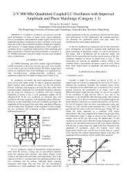
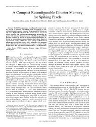
130 IEEE TRANSACTIONS ON CIRCUITS AND SYSTEMS—I: FUNDAMENTAL THEORY AND APPLICATIONS, VOL. 45, NO. 2, FEBRUARY 1998results <strong>in</strong> a spatio–temporal filter tuned to velocities with thesame magnitude <strong>in</strong> the opposite direction.CNN spatio–temporal <strong>Gabor</strong>-type filters constructed <strong>in</strong> thisway are separable <strong>in</strong> space <strong>and</strong> time. 3-D spatio–temporal<strong>Gabor</strong> filters are also space–time separable if their covariancematrices have the formAn important difference between <strong>Gabor</strong> filters <strong>and</strong> the CNNfilters is that <strong>Gabor</strong> filters are noncausal <strong>in</strong> space <strong>and</strong> time,while the CNN filters are noncausal <strong>in</strong> space, but causal <strong>in</strong>time.In order to ensure space–time separability, the spatial filter<strong>in</strong>gCNN’s must settle much faster than the time scales <strong>of</strong> theimage motion so that their outputs at any time are essentiallythe result <strong>of</strong> spatial filter<strong>in</strong>g the <strong>in</strong>put at time . Fortunately, itis easy to design a VLSI implementation <strong>of</strong> the CNN spatialfilters with settl<strong>in</strong>g times on the order <strong>of</strong> microseconds orfaster. The time scale <strong>of</strong> image motion is usually on the order<strong>of</strong> milliseconds. For example, video frame rates are about oneframe every 30–40 ms.There are several advantages to this spatio–temporal filter<strong>in</strong>garchitecture. First, multiple filters tuned to different velocitiescan be obta<strong>in</strong>ed by cascad<strong>in</strong>g the same spatio–temporalfilter<strong>in</strong>g stage with different temporal filters. S<strong>in</strong>ce all <strong>of</strong> thefilters share the same spatial filter<strong>in</strong>g stage, the differencesbetween their outputs are purely a function <strong>of</strong> the temporalvariation <strong>of</strong> the image, i.e., the motion. Second, the temporalfilter<strong>in</strong>g at each pixel is <strong>in</strong>dependent <strong>of</strong> the filter<strong>in</strong>g at the rest<strong>of</strong> the pixels. S<strong>in</strong>ce the output <strong>of</strong> the spatial frequency stageis b<strong>and</strong>limited, it can be subsampled without distortion due toalias<strong>in</strong>g. Therefore, it is not necessary to build a temporal filterat every pixel <strong>of</strong> the output. This can result <strong>in</strong> a significantsav<strong>in</strong>g <strong>in</strong> chip area.Example 4: Denote the output <strong>of</strong> the spatial filter<strong>in</strong>g stageat a pixel <strong>and</strong> time by . One possible cont<strong>in</strong>uoustime temporal filter [38] tuned to has outputwhich satisfiesFig. 7.(a)(b)(a) Contour plot <strong>and</strong> (b) mesh plot <strong>of</strong> the magnitude <strong>of</strong> the CNNspatio–temporal filter’s frequency response for 1-D images. The parametersused were = = 0:3; ! xo =2atan0:5, <strong>and</strong> ! to =0:3:This filter istuned to velocities v = 00:32.impulse response is the product <strong>of</strong> the spatial <strong>and</strong> temporalimpulse responseswhere. It has frequency responseThe comb<strong>in</strong>ed spatio–temporal frequency response is the product<strong>of</strong> the spatial <strong>and</strong> temporal frequency responses. Us<strong>in</strong>g thespatial filter<strong>in</strong>g stage <strong>of</strong> Example 1, the frequency response iswhose magnitude is plotted <strong>in</strong> Fig. 7. S<strong>in</strong>ce the correspond<strong>in</strong>gimpulse response is complex valued, the frequency responseis not symmetric with respect to the orig<strong>in</strong>. Due to spatialsampl<strong>in</strong>g, the spatio–temporal frequency response is periodic<strong>in</strong> with period . There is no periodicity <strong>in</strong> s<strong>in</strong>cethe temporal filter operates <strong>in</strong> cont<strong>in</strong>uous time. Similarly, theIntuitive <strong>in</strong>sight <strong>in</strong>to the operation <strong>of</strong> the spatio–temporal filtercan be ga<strong>in</strong>ed by consider<strong>in</strong>g the effect <strong>of</strong> the temporal filteron one pixel <strong>in</strong> isolation s<strong>in</strong>ce the temporal filter<strong>in</strong>g stageprocesses each output pixel <strong>of</strong> the spatial filter <strong>in</strong>dependently.Assum<strong>in</strong>g uniform translation, the output <strong>of</strong> the spatial filter<strong>in</strong>gstage at pixel <strong>and</strong> time can be written aswhere is constant <strong>and</strong> varies slowly <strong>in</strong> <strong>and</strong> .The output <strong>of</strong> the spatial filter at a fixed pixel rotates aroundthe orig<strong>in</strong> <strong>of</strong> the complex plane with frequency . Thespeed <strong>of</strong> rotation is proportional to the speed <strong>of</strong> translation. Thedirection <strong>of</strong> rotation depends on the direction <strong>of</strong> translation.Assum<strong>in</strong>g , the direction <strong>of</strong> rotation is clockwisefor positive velocities <strong>and</strong> counterclockwise for negative (seeFig. 8).
SHI: GABOR-TYPE FILTERING IN SPACE AND TIME WITH CELLULAR NEURAL NETWORKS 131Fig. 8.The output <strong>of</strong> the spatial filter<strong>in</strong>g stage at a given pixel rotates around the orig<strong>in</strong> <strong>of</strong> the complex plane. This figure shows the outputs at pixel n <strong>of</strong> thespatial filter<strong>in</strong>g stage <strong>in</strong> Example 1 with = 0:3 <strong>and</strong> ! xo =0:93 for image <strong>in</strong>puts consist<strong>in</strong>g <strong>of</strong> impulses located at different pixels near n. If the impulseis translat<strong>in</strong>g uniformly, the output rotates around the orig<strong>in</strong> clockwise for positive velocities <strong>and</strong> counterclockwise for negative velocities.Fig. 10. A circuit implementation <strong>of</strong> the second-order differential (9) us<strong>in</strong>gthree operational amplifiers. Resistors are labeled by their conductances.<strong>and</strong> imag<strong>in</strong>ary parts <strong>of</strong> the temporal filter output. These satisfythe follow<strong>in</strong>g real valued differential equation:(9)Fig. 9. The derivative <strong>of</strong> along trajectories <strong>of</strong> the unforced temporal filterfor = 00:7 <strong>and</strong> ! to =1illustrates that the system is a damped l<strong>in</strong>earoscillator. Trajectories naturally tend to rotate counterclockwise about theorig<strong>in</strong>.The differential equation satisfied by the temporal filtercorresponds to a damped l<strong>in</strong>ear oscillator forced by the output<strong>of</strong> the spatial filter. The derivative along different trajectories<strong>of</strong> the unforced system are shown <strong>in</strong> Fig. 9 for .Ifthe velocity is negative, the <strong>in</strong>put rotates counterclockwise,facilitat<strong>in</strong>g the natural motion <strong>of</strong> output trajectories <strong>and</strong> lead<strong>in</strong>gto a large response. For positive velocity, the <strong>in</strong>put rotationopposes the natural motion, lead<strong>in</strong>g to a small response.In an analog circuit, the filter can be implemented with twocapacitors whose voltages represent the real <strong>and</strong> imag<strong>in</strong>aryparts <strong>of</strong> the output. Let <strong>and</strong> denote the realWrit<strong>in</strong>g KCL at the <strong>in</strong>vert<strong>in</strong>g <strong>in</strong>puts <strong>of</strong> the first <strong>and</strong> thirdoperational amplifiers <strong>and</strong> assum<strong>in</strong>g unit capacitance, it canreadily be shown that the circuit shown <strong>in</strong> Fig. 10 implementsthis differential equation. To cascade this temporal filter withthe spatial filter <strong>in</strong> Example 1, the <strong>in</strong>puts <strong>and</strong>should be equal to the voltages <strong>and</strong> from thebottom <strong>and</strong> top rows <strong>of</strong> Fig. 4.IV. CONCLUSIONThis paper has def<strong>in</strong>ed a class <strong>of</strong> <strong>Gabor</strong>-type spatial <strong>and</strong>spatio–temporal filters which posses the important properties<strong>of</strong> filters used <strong>in</strong> phase-based algorithms for computer vision.<strong>Gabor</strong>-type filters can be implemented us<strong>in</strong>g CNN’s. It ispossible to convert any low-pass spatial filter<strong>in</strong>g CNN <strong>in</strong>to acorrespond<strong>in</strong>g <strong>Gabor</strong>-type filter<strong>in</strong>g CNN by a simple transformation<strong>of</strong> the clon<strong>in</strong>g template coefficients. Spatio–temporal
132 IEEE TRANSACTIONS ON CIRCUITS AND SYSTEMS—I: FUNDAMENTAL THEORY AND APPLICATIONS, VOL. 45, NO. 2, FEBRUARY 1998filters tuned to different velocities can be obta<strong>in</strong>ed by cascad<strong>in</strong>gthe spatial filter outputs with appropriately designedtemporal b<strong>and</strong>pass filters.Ongo<strong>in</strong>g work <strong>in</strong>cludes the design <strong>and</strong> fabrication <strong>of</strong> thearchitecture described <strong>in</strong> Example 1 us<strong>in</strong>g the 2.0- m processprovided by MOSIS [39]. Future work <strong>in</strong>cludes <strong>in</strong>corporat<strong>in</strong>gthis <strong>in</strong>to a chip implement<strong>in</strong>g a spatio–temporal filter,as described <strong>in</strong> Example 4. We are also <strong>in</strong>vestigat<strong>in</strong>g theapplication <strong>of</strong> these chips to various computer-vision taskssuch as b<strong>in</strong>ocular stereo vergence control <strong>and</strong> computation <strong>of</strong>time-to-contact [26].REFERENCES[1] D. <strong>Gabor</strong>, “Theory <strong>of</strong> communication,” J. Inst. Elect. Eng. London, vol.93, pp. 429–457, 1946.[2] S. Marceljia, “Mathematical description <strong>of</strong> the responses <strong>of</strong> simplecortical cells,” J. Opt. Soc. Amer., vol. 70, pp. 1297–1300, Nov. 1980.[3] J. G. Daugman, “Two-dimensional spectral analysis <strong>of</strong> cortical receptivefield pr<strong>of</strong>iles,” Vision Res., vol. 20, pp. 847–856, 1980.[4] E. H. Adelson, <strong>and</strong> J. R. Bergen, “Spatiotemporal energy models forthe perception <strong>of</strong> motion,” J. Opt. Soc. Amer. A, Opt. Image Sci., vol.2, pp. 284–299, Feb. 1985.[5] J. Barron, D. S. Fleet, S. S. Beauchem<strong>in</strong>, <strong>and</strong> T. A. Burkitt, “Performance<strong>of</strong> optical flow techniques,” <strong>in</strong> Proc. IEEE CVPR, Champaign,IL, 1992, pp. 236–242.[6] L. O. Chua <strong>and</strong> L. Yang, “Cellular neural networks: Theory,” IEEETrans. Circuits Syst., vol. 35, pp. 1257–1272, Oct. 1988.[7] , “Cellular neural networks: Applications,” IEEE Trans. CircuitsSyst., vol. 35, pp. 1273–1290, Oct. 1988.[8] L. O. Chua <strong>and</strong> T. Roska, “The CNN paradigm,” IEEE Trans. CircuitsSyst. I, vol. 40, pp. 147–156, Mar. 1993.[9] J. M. Cruz <strong>and</strong> L. O. Chua, “A CNN chip for connected componentdetection,” IEEE Trans. Circuits Syst., vol. 38, pp. 812–817, July 1991.[10] S. Espejo, R. Carmona, R. Dom<strong>in</strong>guez-Castro, <strong>and</strong> A. Rodriguez-Vazquez, “A CNN universal chip <strong>in</strong> CMOS technology,” Int. J. CircuitTheory Applicat., vol. 24, pp. 93–109, 1996.[11] P. K<strong>in</strong>get <strong>and</strong> M. Steyaert, “An analog parallel array processor for realtimesensor signal process<strong>in</strong>g,” <strong>in</strong> IEEE Int. Solid-State Circuits Conf.Dig. Tech. Papers, San Francisco, CA, 1996, pp. 92–93.[12] T. Sanger, “Stereo disparity computation us<strong>in</strong>g <strong>Gabor</strong> filters,” Biol.Cybern., vol. 59, no. 6, pp. 405–418, 1988.[13] R. Wilson <strong>and</strong> H. Knutsson, “A multiresolution stereopsis algorithmbased on the <strong>Gabor</strong> representation,” <strong>in</strong> 3rd Int. Conf. Image Process<strong>in</strong>gApplicat., Warwick, U.K., July 1989, pp. 19–22.[14] A. D. Jepson <strong>and</strong> M. Jenk<strong>in</strong>, “The fast computation <strong>of</strong> disparity fromphase differences,” <strong>in</strong> Computer Vision-ECCV90, O. Faugeras, Ed.Berl<strong>in</strong>, Germany: Spr<strong>in</strong>ger-Verlag, 1990, pp. 50–55.[15] K. Langley, T. J. Atherton, R. G. Wilson, <strong>and</strong> M. H. E. Larcombe,“Vertical <strong>and</strong> horizontal disparities from phase,” <strong>in</strong> Computer Vision-ECCV90, O. Faugeras, Ed. Berl<strong>in</strong>, Germany: Spr<strong>in</strong>ger-Verlag, 1990,pp. 315–325.[16] D. J. Fleet, A. D. Jepson, <strong>and</strong> M. R. M. Jenk<strong>in</strong>, “Phase-based disparitymeasurement,” CVGIP Image Underst<strong>and</strong><strong>in</strong>g, vol. 53, no. 2, pp.198–210, Mar. 1991.[17] C. Chang <strong>and</strong> S. Chatterjee, “Rang<strong>in</strong>g through <strong>Gabor</strong> logons—A consistent,hierarchical approach,” IEEE Trans. Neural Networks, vol. 4,pp. 827–43, Sept. 1993.[18] C.-J. Westelius, H. Knutsson, J. Wiklund, <strong>and</strong> C.-F. West<strong>in</strong>, “Phasebaseddisparity estimation,” <strong>in</strong> Vision as Process, J. L. Crowley <strong>and</strong> H.I. Christensen, Eds. Berl<strong>in</strong>, Germany: Spr<strong>in</strong>ger-Verlag, 1995, Ch. 11,pp. 157–178.[19] W. M. Theimer <strong>and</strong> H. A Mallot, “Phase-based b<strong>in</strong>ocular vergencecontrol <strong>and</strong> depth reconstruction us<strong>in</strong>g active vision,” CVGIP: ImageUnderst<strong>and</strong><strong>in</strong>g, vol. 60, no. 3, pp. 343–358, Nov. 1994.[20] M. Porat <strong>and</strong> Y. Y. Zeevi, “Localized texture process<strong>in</strong>g <strong>in</strong> vision:Analysis <strong>and</strong> synthesis <strong>in</strong> <strong>Gabor</strong>ian space,” IEEE Trans. Biomed. Eng.,vol. 36, pp. 115–29, Jan. 1989.[21] N. Petkov, P. Kruiz<strong>in</strong>ga, <strong>and</strong> T. Lourens, “Biologically motivatedapproach to face recognition,” <strong>in</strong> New Trends Neural Computation, Int.Workshop Artificial Neural Networks, Seville, Spa<strong>in</strong>, 1993, pp. 68–77.[22] D. J. Heeger, “Model for the extraction <strong>of</strong> image flow,” J. Opt. Soc.Amer. A, vol. 4, pp. 1455–1471, Aug. 1987.[23] N. M. Gryzwacz <strong>and</strong> A. L. Yuille, “A model for the estimate <strong>of</strong> localimage velocity by cells <strong>in</strong> the visual cortex,” <strong>in</strong> Proc. R. Soc. Lond. B,vol. 239, 1990, pp. 129–161.[24] D. J. Fleet, Measurement <strong>of</strong> Image Velocity. Norwell, MA: Kluwer,1992.[25] B. K. P. Horn, Robot Vision. Cambridge, MA: MIT Press, 1986.[26] B. E. Shi, “Second-order CNN arrays for estimation <strong>of</strong> time to contact,”<strong>in</strong> Proc. 4th IEEE Int. Workshop Cellular Neural Networks, Seville,Spa<strong>in</strong>, June 1996, pp. 427–432.[27] R. N. Bracewell, The Fourier Transform <strong>and</strong> Its Applications. NewYork: McGraw-Hill, 1986.[28] L. Raffo, “Resistive network implement<strong>in</strong>g maps <strong>of</strong> <strong>Gabor</strong> functions <strong>of</strong>any phase,” Electron. Lett., vol. 31, no. 22, pp. 1913–1914, Oct. 1995.[29] T. Delbruck, “Silicon ret<strong>in</strong>a with correlation-based, velocity-tuned pixels,”IEEE Trans. Neural Networks, vol. 4, pp. 529–541, May 1993.[30] B. E. Shi, “Spatio–temporal filter<strong>in</strong>g with cellular neural networks,”Ph.D. dissertation, Dept. Elect. Eng. Computer Sci., Univ. CaliforniaBerkeley, 1994.[31] K. R. Crounse <strong>and</strong> L. O. Chua, “Methods for image process<strong>in</strong>g <strong>and</strong>pattern formation <strong>in</strong> cellular neural networks: A tutorial,” IEEE Trans.Circuits Syst. I, vol. 42, pp. 583–601, Oct. 1995.[32] C. Mead, Analog VLSI <strong>and</strong> Neural Systems. Read<strong>in</strong>g, MA: Addison-Wesley, 1989.[33] B. E. Shi <strong>and</strong> L. O. Chua, “Resistive grid image filter<strong>in</strong>g: <strong>in</strong>put/outputanalysis via the CNN framework,” IEEE Trans. Circuits Syst. I, vol. 39,pp. 531–548, July 1992.[34] B. Shi, “<strong>Gabor</strong>-type image filter<strong>in</strong>g with cellular neural networks,” Proc.IEEE Int. Symp. Circuits Syst., vol. 3, pp. 558–561, May 1996.[35] K. F. Hui <strong>and</strong> B. E. Shi, “Robustness <strong>of</strong> CNN implementations for<strong>Gabor</strong>-type filter<strong>in</strong>g,” <strong>in</strong> IEEE Asia–Pacific Conf. Circuits Syst., Seoul,Korea, Nov. 1996, pp. 105–108.[36] H. Kobayashi, J. L. White, <strong>and</strong> A. A. Abidi, “An active resistor networkfor Gaussian filter<strong>in</strong>g <strong>of</strong> images,” IEEE J. Solid-State Circuits, vol. 26,pp. 738–748, May 1991.[37] T. Poggio, H. Voorhees, <strong>and</strong> A. Yuille, “A regularized solution to edgedetection,” MIT, Cambridge, A.I. Memo 833, May 1985.[38] B. E. Shi, “Spatio–temporal image filter<strong>in</strong>g with cellular neural networks,”Proc. IEEE Int. Conf. Neural Networks, vol. 3, Wash<strong>in</strong>gton,DC, June 1996, pp. 141–1415.[39] , “An analog neural network for <strong>Gabor</strong>-type image filter<strong>in</strong>g,” <strong>in</strong>Proc. Int. Conf. Neural Inform. Process<strong>in</strong>g, vol. 1, Hong Kong, Sept.1996, pp. 417–422.Bertram E. Shi (S’93–M’95) received the B.S.<strong>and</strong> M.S. degrees <strong>in</strong> electrical eng<strong>in</strong>eer<strong>in</strong>g fromStanford University, Stanford, CA, <strong>in</strong> 1987 <strong>and</strong>1988, respectively, <strong>and</strong> the Ph.D. degree <strong>in</strong> electricaleng<strong>in</strong>eer<strong>in</strong>g from the University <strong>of</strong> California atBerkeley, <strong>in</strong> 1994.S<strong>in</strong>ce 1994, he has been an Assistant Pr<strong>of</strong>essor<strong>in</strong> the <strong>Department</strong> <strong>of</strong> Electrical <strong>and</strong> <strong>Electronic</strong> Eng<strong>in</strong>eer<strong>in</strong>g,Hong Kong University <strong>of</strong> Science <strong>and</strong>Technology, Kowloon, Hong Kong. His research<strong>in</strong>terests are <strong>in</strong> CNN’s, image process<strong>in</strong>g, computervision, <strong>and</strong> speech recognition.