Buckling Restrained Braced Frames - SEAoT
Buckling Restrained Braced Frames - SEAoT
Buckling Restrained Braced Frames - SEAoT

Create successful ePaper yourself
Turn your PDF publications into a flip-book with our unique Google optimized e-Paper software.
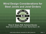
<strong>Buckling</strong>-<strong>Restrained</strong> <strong>Braced</strong> <strong>Frames</strong>byWalterio A. López, SERafael Sabelli, SERutherford & ChekeneWalter P Moore
<strong>Buckling</strong>-<strong>Restrained</strong> <strong>Braced</strong> <strong>Frames</strong>(BRBFs)• Code Intent• How BRBs work• Brief History of BRBFs in US Codes• Sample BRBF Construction• Brief treatment on testing• Building-Code Design• Design Methodology• Specification, Other Issues• Gusset Connections• Summary
Code Intent
Building-Code PhilosophyObjective:Prevent collapse in the extremeearthquake likely to occur at abuilding site.Objectives are not to:limit damagemaintain functionprovide for easy repair
To survive a strong earthquakewithout collapse:Design for Ductile BehaviorMaterial DuctilityMember DuctilitySystem Ductility
AISC MethodologyDesignate fusesMembers that undergo inelastic strainProvide ductility in fuse membersPrevent local bucklingPrevent member instabilityPrevent connection failureDesign system to ensure ductility is concentratedin fuses
How BRBs work
What is a <strong>Buckling</strong>-restrained Brace?Two DefinitionsStressresisted bysteel core<strong>Buckling</strong>resisted bysleeveDe-Coupled Stress and <strong>Buckling</strong>(Mechanics Definition)Balanced Hysteresis(Performance Definition)
BRB Definitions Explained:Conventional BracingBrace behavior isasymmetric withrespect to tensionand compressionand is subject tostrength andstiffnessdegradationR y A g F yP crTensionCompression
BRB Definitions Explained:Sleeved ColumnSteel core achieves F y Aλ c ~ 0kl/ r ~ 0Sleeve achieves π 2 EI/L 2Stress is zeroNo material stress limitCompression StrengthF y Aπ 2 E IL 20 1 2 3Slenderness Parameter λ c
Brief History of BRBFsin US Codes
Historical Background1 st BRBF paper: 2000 SEAOC ConventionBRBF design presentations:SEAOC: 2001-2006NASCC: 2004, 2005Steel TIPS Seminars: 2004ASCE Structures Congress: 2005AISC braced frame seminars: 2005, 2006BRBFs in U.S. to date: >100 bldgs, >15,000BRBs
Background (recent past/present)SEAOC/AISC BRBF committee
Background (present)
Sample BRBF Construction
Sample Construction
Sample Construction
<strong>Buckling</strong>-<strong>Restrained</strong> Brace Types<strong>Buckling</strong><strong>Restrained</strong>BracePowerCatBraceUnbonded BraceACMEBracingCompany
GEM High-Expectation Entrepreneurship 2005The prevalence rates of higher-growth activity (thosenascent entrepreneurs and baby businesses who expect50 or more jobs in five years) follow similar patterns tothose described above. Figure 5 shows the prevalence of50 or higher job expectations in different world regions.Figure 6 shows the prevalence of 50 or higher jobexpectations for selected countries.Figure 5Total Entrepreneurial Activity by Growth Expectation in Different World Regions: High-Expectation Nascent andBaby Businesses which Expect 50 or More Jobs in Five YearsOverall, the participation levels in “50+ activity” areapproximately half the level of “20+ activity”. For regions,North America (USA and Canada) depicts the highestparticipation rate, with a mean participation level of 0.6%among the adult-age population. Note that the 95%confidence interval stretches from 0.5% to 0.7%. Thegroup of Anglo-Saxon countries, developing Asiancountries, and Oceania countries depicts similar levels, atapproximately 0.5%. The differences between the first fourgroups are not statistically significant. African and LatinAmerican participation rates are significantly lower thanthat of North America and Anglo-Saxon countries, atapproximately 0.3%. Europe and highly developed Asiancountries depict the lowest levels of “50+ activity”, with aEuropean participation rate of approximately 0.15%.Figure 6Total Entrepreneurial Activity by Growth Expectation in Five Countries: High-Expectation Nascent and BabyBusinesses which Expect 50 or More Jobs in Five Years% of adult-age population participating in high-expectationentrepreneurial activity (50 or more expected jobs)% of adult-age population participating in high-expectationentrepreneurial activity (50 or more expected jobs)20
Selected Testing DataLiteratureReferenceTest TypeNumberof TestedBracesBraceStrain(%)SIE, 1999 Uniaxial 3 2.1SIE, 2001 Uniaxial 2 2.1UC Berkeley, 2002Frame(Subassemblage)3 1.8 - 2.1Merritt et al., 2003a Subassemblage 6 2.4 - 2.7Merritt et al., 2003b Subassemblage 8 1.8 - 2.6Merritt et al., 2003c Uniaxial 2 1.6, 1.7SIE, 2003 Subassemblage 4 1.6 – 3.0
BRB Tests Short Summary• About 50+ different brace tests have beenperformed in support of US projects• All tests results so far have met Appendix T’sacceptance criteria• Tests have included Appendix T, moment frame,near-field, and fatigue displacement protocols• Kinematic rotations of brace ends were notdetrimental to brace performance
Building-Code Design
ASCE 7 2005 (with Supplement 1)R Values7 for Basic BRBF System8 for BRBF System with Rigid Beam-ColumnConnections8 for BRBF/SMF Dual System
ASCE 7 2005 (with Supplement 1)Ω o Values2 for Basic BRBF System2 1 / 2 for BRBF System with Rigid Beam-ColumnConnections2 1 / 2 for BRBF/SMF Dual System
ASCE 7 2005 (with Supplement 1)C d Values5 1 / 2 for Basic BRBF System5 for BRBF System with Rigid Beam-ColumnConnections5 for BRBF/SMF Dual System
ASCE 7 2005 (with Supplement 1)Height LimitsSeparated by Seismic Design Category:B&C D E FNL 160* 160 100 for Basic BRBF SystemNL 160* 160 100 for BRBF System with RigidBeam-Column ConnectionsNL NL NL NL for BRBF/SMF Dual System(NL = Not Limited)*Can be increased to 240 for regular buildings.
ASCE 7 2005 (with Supplement 1)Coefficients for Determination ofApproximate PeriodT a = C r ( H / ft. ) xC rx = 0.75= 0.03 (ASCE to incorporate)(Similar to EBF)
Combined effect of R and TDesign Base ShearSCBFBRBFSCBF BuildingBRBF BuildingPeriod
Design Methodology
Design ProcedureDefine appropriate BRB modelingDetermine required brace strengthCheck driftDetermine brace displacements at 2.0 Δ mCompare required displacements to existing testsPlan and conduct new tests?Determine adjusted BRB strengths at 2.0 Δ mRequires test data or manufacturer’s summaryCalculate required strength of columns, beams, andconnections based on adjusted BRB strengths
BRBF Design Methodology• BRB is energy dissipater• Steel core materialspecified as mild & ductile• Design checks:• BRB φP n• Global drift• BRB deformation, Δ bM• Adjusted BRB strengths• Beam R u /φR n• Column R u /φR n• Connections R u /φR n
AnalysisGravity LoadSize frame to resist 100% of gravityAll load combinationsDo not model braces as resisting gravity loadCheck that braces do not yield under Live LoadSeismic LoadSize braces for seismic load onlyDo not model braces to resist gravity loadSize for 100% of seismic load?Or consider shear in columnsFound by analysisSize frame considering plastic mechanism
Design SummaryLoad CombinationGravity Seismic1.2D + 1.6L 1.2D + 0.5L + EFrameDesign for 100% ofloadDesign for maximumbrace forces, plus 100% ofgravityBracesCheck to makesure live load doesnot cause (cyclic)yieldingDesign for seismic forcefrom analysis; do notinclude gravity
Brace StiffnessK br = P/ΔΔL y~ PL y /A y E= 0.5-0.8 L(depending onbrace type andconfiguration)K br = 1.2 - 2.0 A y E /LFlexibilityL yEA scL L yEA nonyielding
BRB ModelingK br = 1.3 A sc E /L ? K br = 1.6 A sc E /L ?
BRB Modeling (Nonlinear)Isotropic and kinematic strain hardeningDifference in tension/compression valuesModified DRAIN, PERFORM 3D
Steel Core Material• Specifications• ASTM A36 Grade 36/42• JIS G3136 SN400B• Wide range of yield strength not desired• Solution: supplementary yield strengthrequirements verified by coupon tests• Current practice: material procured based onMTRs, coupon tests performed prior tofabrication
Preliminary BRB DesignFP u=F2 cosθAssume bracesresist 100% ofstory shearθAsc≥φPuFyscDesign braces tocalculated capacity(P u = φP n = φF ysc A sc )
BRB Axial Deformation CheckCompute elastic story drift Δ XExtract from analysis program Δ bX = Δ brace at Δ Xstory drift
BRB Axial Deformation CheckΔ bXis computed at largest elastic story drift(ρ = 1.0 for drift)Compute Δ bM = C d Δ bX = Δ brace at Δ M story driftCompute max. brace strain ε MAX = 2.0Δ bM / L yscε MAX cannot exceed maximum value testedIf ε MAX exceeds tested values, resize BRB
BRB Axial Deformation ComparisonFor a ASCE 7 earthquake (2/3 of MCE)2.0 Δ bm ~ 10 Δ by (elastic methods, Ch. 16)Mean = 9-11 Δ by (Sabelli, Fahnestock)For a 2%/50 year eventNot addressed in codesMean = 17-19 Δ by (Sabelli, Fahnestock)• Ductilities underestimated but not forces• Solution: fabricate BRBs to Δ by larger thanpredicted by elastic methods
Plastic MechanismAll braces yieldingTension or compressionStrain Hardened“Adjusted strength”= Maximum forceBased on first mode
BRB Adjusted StrengthCompression: βωR y F ysc A scTension: ωR y F ysc A scAdjusted for Various Factorsω Strain-Hardeningβ Compression OverstrengthR y Material OverstrengthIf F y is used as core yield strength F ysc , R y is > 1.0If F ysc is taken from material coupon test, R y = 1.0.
BRB Adjusted StrengthFactorsFactors Taken from Test Results within 2.0Δ m .Compression Strength Adjustment Factorβ = C max /T maxStrain-Hardening Adjustment Factorω = T max /F y AProvided by brace manufacturers
BRB Uniaxial Test ResultsHysteresis courtesy of SIE, Inc.
BRB Adjusted Strength (example)ε MAX = 0.98 % at 2.0Δ bMGo to graph from BRB manufacturerand obtain:ω = 1.22ωβ = 1.25β = ωβ/ω= 1.25/1.22= 1.03
BRB Adjusted StrengthCase at inverted-V beam
Frame Design: Model BRB ForcesDirectlyωR y F ysc A scβωR y F ysc A scβωR y F ysc A scωR y F ysc A scωR y F ysc A scβωR y F ysc A scβωR y F ysc A scωR y F ysc A scωR y F ysc A scβωR y F ysc A scColumn flexural forces not calculatedCombine with 1.2D + 0.5 L + 0.2 S ds D
Frame Design: Model BRB forces UsingTemperatureE = 1 ksiα = 1/ o FΔ T = ωR y F yscTensionAxial force approximationColumn flexural forces not calculatedΔ T = βωR y F yscCompressionCombine with 1.2D + 0.5 L + 0.2 S ds D
Specification, Other Issues
Use of Proprietary BRBsEngineer Specifies:Brace StrengthBrace Core Area (or stiffness)Maximum and Minimum F yDisplacement rangeManufacturer Provides:Braces that meet the specificationTest data that qualifies the braces
Typical Specification of BRB Size- A SCUncertainty in strength (example)CalculationsφP n = 0.9A ysc (38 ksi)R y = 46 ksi/38 ksi = 1.21DrawingsA sc = 8.5 in. 2 (for example)Specifications38 ksi ≤ F ysc ≤ 46 ksiManufactureA sc = 8.5 in. 2323 kips ≤ P ysc ≤ 391 kipsProportioning of strength likely similar to design
Alternate Specification of BRB Size- P yscUncertainty in stiffness (example)CalculationsφP n = 0.9A sc F ysc where F ysc is measured during manufactureand A sc is adjusted accordinglyR y = 1.0A sc = φP n /0.9 (44 ksi) [reasonably low stiffness for analysis]DrawingsP ysc = 323 kips (= P u /φ)Specifications38 ksi ≤ F ysc ≤ 46 ksiManufactureP ysc= 323 kips7.0 in. 2 ≤ Asc ≤ 8.5 in. 2Proportioning of stiffness likely similar to design
Construction AdministrationGeneral contractorSteel fabricatorBRBDetailerDrawingExchangeFabricatorDetailerCoordinated submittals:BRBs, gusset plates, frames
Code Issues• BRB is a better brace that doesn't buckle.• BRB is a performance-specification item.• Single diagonals in one direction and stackedchevron allowed without penalty.• BRB and gussets often need not be fireproofed.• If manufactured in approved shop, inspectionsmay be waived.• Non-structural attachments to casing notprohibited.
Gusset Connections
Sample Connections
Alternative ConnectionsDirect welding of coreDirect bolting of coreCourtesy ofCoreBraceCourtesy ofSTAR Seismic
Gusset Plate Design Issues•Adjusted BRB strengths readilydetermined from backbonecurve (first validation ofmethodology)•Frame fixity must beacknowledged in analyses•Recognize that cyclic testing ofgusset plates not fullydeveloped•Avoid unnecessary connectionrestraint
Potential Connection IssuesBeam (or column) yield at
Potential Connection IssuesCourtesy of K.C. Tsai
Pin ConnectionCourtesy ofL. Fahnestock
Summary
BRBF Design Summary• BRB is energydissipater• Check BRB ductilitydemands• Check surroundingelements for adjustedBRB strengths
Overall SummaryBRBs harness steel ductility to providemember ductilityBRBF provide a ductile system ifConnection failure is precludedBraces are proportioned to earthquake demandFrame is designed for plastic mechanismBraces are properly specified.
Thank You