Conditions of Pyrolythic Processes in Multi Chamber Furnaces for ...
Conditions of Pyrolythic Processes in Multi Chamber Furnaces for ...
Conditions of Pyrolythic Processes in Multi Chamber Furnaces for ...

You also want an ePaper? Increase the reach of your titles
YUMPU automatically turns print PDFs into web optimized ePapers that Google loves.
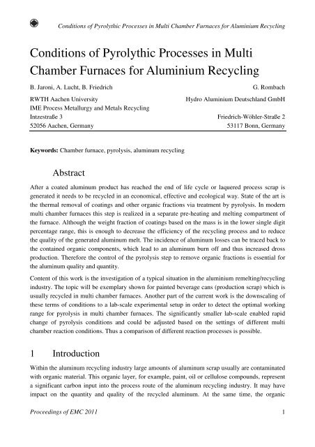
<strong>Conditions</strong> <strong>of</strong> <strong>Pyrolythic</strong> <strong>Processes</strong> <strong>in</strong> <strong>Multi</strong> <strong>Chamber</strong> <strong>Furnaces</strong> <strong>for</strong> Alum<strong>in</strong>ium Recycl<strong>in</strong>g<strong>Conditions</strong> <strong>of</strong> <strong>Pyrolythic</strong> <strong>Processes</strong> <strong>in</strong> <strong>Multi</strong><strong>Chamber</strong> <strong>Furnaces</strong> <strong>for</strong> Alum<strong>in</strong>ium Recycl<strong>in</strong>gB. Jaroni, A. Lucht, B. Friedrich G. RombachRWTH Aachen UniversityHydro Alum<strong>in</strong>ium Deutschland GmbHIME Process Metallurgy and Metals Recycl<strong>in</strong>gIntzestraße 3 Friedrich-Wöhler-Straße 252056 Aachen, Germany 53117 Bonn, GermanyKeywords: <strong>Chamber</strong> furnace, pyrolysis, alum<strong>in</strong>um recycl<strong>in</strong>gAbstractAfter a coated alum<strong>in</strong>um product has reached the end <strong>of</strong> life cycle or laquered process scrap isgenerated it needs to be recycled <strong>in</strong> an economical, effective and ecological way. State <strong>of</strong> the art isthe thermal removal <strong>of</strong> coat<strong>in</strong>gs and other organic fractions via treatment by pyrolysis. In modernmulti chamber furnaces this step is realized <strong>in</strong> a separate pre-heat<strong>in</strong>g and melt<strong>in</strong>g compartment <strong>of</strong>the furnace. Although the weight fraction <strong>of</strong> coat<strong>in</strong>gs based on the mass is <strong>in</strong> the lower s<strong>in</strong>gle digitpercentage range, this is enough to decrease the efficiency <strong>of</strong> the recycl<strong>in</strong>g process and to reducethe quality <strong>of</strong> the generated alum<strong>in</strong>um melt. The <strong>in</strong>cidence <strong>of</strong> alum<strong>in</strong>um losses can be traced back tothe conta<strong>in</strong>ed organic components, which lead to an alum<strong>in</strong>um burn <strong>of</strong>f and thus <strong>in</strong>creased drossproduction. There<strong>for</strong>e the control <strong>of</strong> the pyrolysis step to remove organic fractions is essential <strong>for</strong>the alum<strong>in</strong>um quality and quantity.Content <strong>of</strong> this work is the <strong>in</strong>vestigation <strong>of</strong> a typical situation <strong>in</strong> the alum<strong>in</strong>ium remelt<strong>in</strong>g/recycl<strong>in</strong>g<strong>in</strong>dustry. The topic will be exemplary shown <strong>for</strong> pa<strong>in</strong>ted beverage cans (production scrap) which isusually recycled <strong>in</strong> multi chamber furnaces. Another part <strong>of</strong> the current work is the downscal<strong>in</strong>g <strong>of</strong>these terms <strong>of</strong> conditions to a lab-scale experimental setup <strong>in</strong> order to detect the optimal work<strong>in</strong>grange <strong>for</strong> pyrolysis <strong>in</strong> multi chamber furnaces. The significantly smaller lab-scale enabled rapidchange <strong>of</strong> pyrolysis conditions and could be adjusted based on the sett<strong>in</strong>gs <strong>of</strong> different multichamber reaction conditions. Thus a comparison <strong>of</strong> different reaction processes is possible.1 IntroductionWith<strong>in</strong> the alum<strong>in</strong>um recycl<strong>in</strong>g <strong>in</strong>dustry large amounts <strong>of</strong> alum<strong>in</strong>um scrap usually are contam<strong>in</strong>atedwith organic material. This organic layer, <strong>for</strong> example, pa<strong>in</strong>t, oil or cellulose compounds, representa significant carbon <strong>in</strong>put <strong>in</strong>to the process route <strong>of</strong> the alum<strong>in</strong>um recycl<strong>in</strong>g <strong>in</strong>dustry. It may haveimpact on the quantity and quality <strong>of</strong> the recycled alum<strong>in</strong>um. At the same time, the organicProceed<strong>in</strong>gs <strong>of</strong> EMC 2011 1
Jaroni, Lucht, Rombach, Friedrichcomponents could also be converted us<strong>in</strong>g a pyrolysis to potential energy resource, so that the fuelconsumption and thus the recycl<strong>in</strong>g costs are reduced. The comb<strong>in</strong>ation <strong>of</strong> a pyrolysis withsimultaneous remelt<strong>in</strong>g <strong>of</strong> the scrap is achieved through the use <strong>of</strong> multi chamber furnaces. A rampwhich is used <strong>for</strong> the pyrolysis step is <strong>in</strong> modern chamber furnace located <strong>in</strong>side the melt<strong>in</strong>gchamber.The aim <strong>of</strong> this part <strong>of</strong> the current work is to <strong>in</strong>vestigate a more complete picture <strong>of</strong> the compositionand amount <strong>of</strong> pyrolysis products through a variation <strong>of</strong> the oxygen concentration and scrapproperties <strong>for</strong>med and to determ<strong>in</strong>e the exact duration <strong>of</strong> the pyrolysis process. The obta<strong>in</strong>edanalysis results are subsequently compared with each other and with those <strong>of</strong> a multi chamberfurnace to show the potential <strong>for</strong> improvement.2 Basics <strong>of</strong> thermal decomposition <strong>of</strong> organic materialIn general the thermal decomposition <strong>of</strong> carbon material with and without oxygen is divided <strong>in</strong>tothree reactions. To make a dist<strong>in</strong>ction between these reactions called pyrolysis, combustion andgasification the oxygen number λ is def<strong>in</strong>ed. The oxygen number λ is the ratio <strong>of</strong> total air amount <strong>in</strong>the system to needed oxygen <strong>for</strong> stoichiometric total combustion. Table 1 shows an overview <strong>of</strong>process parameters and reaction products <strong>of</strong> thermic decomposition reactions [1, 2].Table 1: Explanation <strong>of</strong> carbon decomposition regard<strong>in</strong>g to the oxygen number λ [2]Process ParameterCombustion λ > 1 CO 2 , H 2 OGasification 0 < λ < 1 CO, H 2Pyrolysis λ = 0 C x H y , C fixReactions products (ideal)Autothermal Pyrolysis λ > 0, T < 700 °C C x H y , C fix , CO 2 , H 2 OAutothermal Gasification λ = 0.3 to 0.5, T > 800 °C CO, H 2 , CO 2 , H 2 OFor the combustion <strong>of</strong> carbon conta<strong>in</strong><strong>in</strong>g material e.g. lacquers the oxygen number is bigger thanone. So, that <strong>for</strong> the reaction <strong>of</strong> every mol carbon one or more mol <strong>of</strong> oxygen is available. Suchcombustion reactions generate a lot <strong>of</strong> heat energy as shown <strong>in</strong> equation 1.kJ+ = ∆ = − (1)C(s) O2(g) CO2(g) RH 393.5 molIn variance with the combustion the oxygen number range <strong>for</strong> gasification is between 0 and 1.Because <strong>of</strong> the low oxygen concentration (
<strong>Conditions</strong> <strong>of</strong> <strong>Pyrolythic</strong> <strong>Processes</strong> <strong>in</strong> <strong>Multi</strong> <strong>Chamber</strong> <strong>Furnaces</strong> <strong>for</strong> Alum<strong>in</strong>ium Recycl<strong>in</strong>gFigure 1: De-coat<strong>in</strong>g mechanism [3]Figure 1 shows the reaction dur<strong>in</strong>g an <strong>in</strong>dustrial pyrolysis process with the aim to reduce the totalcarbon amount <strong>of</strong> alum<strong>in</strong>um scrap. In the first step the organic components evaporate and <strong>for</strong>m gasand tar. On the surface <strong>of</strong> the scrap rema<strong>in</strong>s a carbon-conta<strong>in</strong><strong>in</strong>g, tar residue. In the second step <strong>of</strong>the reaction on the surface rema<strong>in</strong><strong>in</strong>g carbon reacts with the added oxygen and burn controlled toCO or CO 2 [3, 4].Organic(s) = Coke(s) + gaseous Components (2)Equation 2 shows the overall pyrolysis reaction. Parallel to the gasification process at sufficientlyhigh temperatures, an autothermal pyrolysis can be generated. In such a state simultaneouslypyrolysis and combustion reactions are runn<strong>in</strong>g. Be<strong>for</strong>e an autothermal pyrolysis can be achievedthe pyrolysis process runs through several phases. Which reactions take place <strong>in</strong> these phasesdepends on temperature. These different reactions are shown below <strong>in</strong> Figure 2 [2, 5].Figure 2: Pyrolytic decomposition <strong>of</strong> organic material depend<strong>in</strong>g to temperature [5]Proceed<strong>in</strong>gs <strong>of</strong> EMC 2011 3
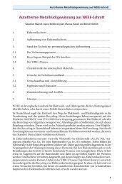
Jaroni, Lucht, Rombach, Friedrich3 Experiment3.1 Feed<strong>in</strong>g MaterialFor the experiments two different types <strong>of</strong> alum<strong>in</strong>ium scrap are used. Oiled scarp and pa<strong>in</strong>ted scrapcom<strong>in</strong>g from beverage can production, because <strong>of</strong> the dimensions <strong>of</strong> the used lab-scale pyrolysisreactor the scrap packages are cut <strong>in</strong>to smaller blocks (60×60×200 mm). Figure 3 shows both scraptypes <strong>in</strong> the lab-scale dimensions. On the cut site the <strong>in</strong>side block structure is fairly visible. It isobvious that the compact<strong>in</strong>g process produces a large number <strong>of</strong> cavities <strong>in</strong>side <strong>of</strong> the block andthus an <strong>in</strong>homogeneous heat conductivity.Figure 3:Feed<strong>in</strong>g materialThe different densities <strong>of</strong> the compacted scrap blocks are a result <strong>of</strong> various shapes <strong>of</strong> the scrapsheet. The pa<strong>in</strong>ted blocks have an average weight <strong>of</strong> 840 g <strong>in</strong> different from oiled blocks with anaverage weight <strong>of</strong> 1050 g. This high deviation depends on the various degree <strong>of</strong> compaction.Another result <strong>of</strong> the different compaction is the higher amount <strong>of</strong> caverns <strong>in</strong>side <strong>of</strong> the pa<strong>in</strong>tedmaterial blocks. The medium weight is a result <strong>of</strong> alum<strong>in</strong>um and lacquer or oil amount. Thepercentage lacquer amount is located between 2 % and 4 %.3.2 EquipmentIn this study, only the carbon decomposition reaction step is simulated and there is no need <strong>for</strong> ameltdown <strong>in</strong> the first experiment step. Thus, there is the possibility to <strong>in</strong>vestigate the pyrolysedalum<strong>in</strong>um scrap after the experiment and draw a conclusion from the weight loss. A steal reactor isconstructed <strong>for</strong> these experiments (Figure 4) to simulate the same conditions that can be found<strong>in</strong>side the melt<strong>in</strong>g chamber <strong>of</strong> a modern chamber furnace especially to adjust different atmospheres.To ma<strong>in</strong>ta<strong>in</strong> a homogeneously distributed gas flow the reactor has a sieve as a false floor. Acommon resistance furnace is used <strong>for</strong> heat<strong>in</strong>g this reactor.4Proceed<strong>in</strong>gs <strong>of</strong> EMC 2011
<strong>Conditions</strong> <strong>of</strong> <strong>Pyrolythic</strong> <strong>Processes</strong> <strong>in</strong> <strong>Multi</strong> <strong>Chamber</strong> <strong>Furnaces</strong> <strong>for</strong> Alum<strong>in</strong>ium Recycl<strong>in</strong>gFigure 4:Used lab-scale reactor with false bottomTo separate the <strong>in</strong>fluence <strong>of</strong> oxygen from other atmosphere components it is possible to adjustdifferent Argon, Oxygen ratios <strong>for</strong> the experiments. Dur<strong>in</strong>g the experiments CO, CO 2 , O 2 , C x H y andtemperature are measured and logged. Figure 5 shows the complete experimental setup.Figure 5:Experimental setup to analyze ma<strong>in</strong> gaseous reaction productsProceed<strong>in</strong>gs <strong>of</strong> EMC 2011 5
Jaroni, Lucht, Rombach, FriedrichTo analyse CO, CO 2 and O 2 a B<strong>in</strong>os 1001 with <strong>in</strong>tegrated Oxynos 100 and a X-am 7000 gas analys<strong>in</strong>gdevices are used redundant. Because <strong>of</strong> <strong>of</strong>f-gas temperatures up to 350 °C a gas cool<strong>in</strong>g systemis used to protect these analys<strong>in</strong>g devices. The FID (Flame Ionization Detector) detects hydrocarbonsand other easily flammable components. The measured data are logged every 10 seconds.4 Experimental resultsIn the first experiment campaign the <strong>in</strong>fluence <strong>of</strong> the oxygen level dur<strong>in</strong>g the pyrolysis is<strong>in</strong>vestigated.After per<strong>for</strong>m<strong>in</strong>g 20 pyrolysis experiments <strong>in</strong> the IME lift resistance heated crucible ovenat 600 °C, the follow<strong>in</strong>g table is created. The weight be<strong>for</strong>e and after the carbon decompositionreaction <strong>of</strong> the used scrap blocks and the oxygen concentration <strong>of</strong> the <strong>in</strong>dividual experiments, whichconsists <strong>of</strong> the flow rates <strong>of</strong> argon and oxygen are illustrated.Table 2:Results <strong>of</strong> the pyrolysis experimentsTrailNo.Weight be<strong>for</strong>epyrolysis[g]Weight afterpyrolysis[g]Weightdifference[g]Difference[%]Gasflow Ar[l/m<strong>in</strong>]Gasflow O 2[l/m<strong>in</strong>]V1 340.0 332.0 8.0 2.4 - - -V2 861.0 841.0 20.0 2.3 20.0 1.2 0.4V3 845.0 824.0 21.0 2.5 20.0 0.0 0.0V4 866.0 847.0 19.0 2.2 20.0 2.0 3.4V5 848.0 828.0 20.0 2.4 20.0 2.0 3.4V6 842.0 823.0 19.0 2.3 20.0 1.5 1.0V7 857.0 836.0 21.0 2.5 20.0 2.6 10.0V8 1076.0 1068.0 8.0 0.7 20.0 0.0 0.0V9 1019.0 1012.0 7.0 0.7 18.7 0.7 2.2V10 833.0 812.0 21.0 2.5 18.2 2.9 10.0V11 542.8 533.0 9.8 1.8 16.5 2.6 2.5V12 598.8 586.2 12.6 2.1 15.2 1.5 2.1V13 563.8 550.6 13.2 2.3 17.4 2.1 3.3V14 561.4 550.9 10.5 1.9 14.5 0.0 0.0V15 425.5 415.0 10.5 2.5 16.6 2.1 2.5V16 542.8 531.7 11.1 2.0 16.6 2.1 2.4V17 577.2 564.9 12.3 2.1 17.7 2.2 3.1V18 562.5 550.7 11.8 2.1 17.7 1.9 1.0V19 567.6 555.9 11.7 2.1 14.6 0.0 0.0V20 572.6 559.6 13.0 2.3 20.0 3.1 1.2In Table 2, all tests per<strong>for</strong>med are listed. Tests 1 to 11 were per<strong>for</strong>med with the orig<strong>in</strong>al reactorconfiguration. In this configuration it was nearly impossible to charge the material <strong>in</strong> the hotO 2[%]6Proceed<strong>in</strong>gs <strong>of</strong> EMC 2011
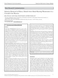
<strong>Conditions</strong> <strong>of</strong> <strong>Pyrolythic</strong> <strong>Processes</strong> <strong>in</strong> <strong>Multi</strong> <strong>Chamber</strong> <strong>Furnaces</strong> <strong>for</strong> Alum<strong>in</strong>ium Recycl<strong>in</strong>greactor. The follow<strong>in</strong>g experiments 12 to 20 were carried out <strong>in</strong> the modified version <strong>of</strong> the reactor.This modification allows to charge <strong>in</strong> the heated reactor without hav<strong>in</strong>g a long <strong>in</strong>fluence <strong>of</strong> thenormal atmosphere dur<strong>in</strong>g charg<strong>in</strong>g. Furthermore, <strong>in</strong> experiments 8 and 9, material contam<strong>in</strong>atedwith oil is used. Experiment 1 is a test trial with a lower scrap amount and there<strong>for</strong>e it is not called<strong>in</strong> <strong>for</strong> the follow<strong>in</strong>g analysis.The comparison <strong>of</strong> weight losses <strong>of</strong> all experiments shows a percentage weight reduction between1.8 to 2.5 wt. %. For this consideration only tests with fully pa<strong>in</strong>ted scrap are used so that the testsdo not <strong>in</strong>volve experiment 8 and 9 <strong>in</strong> the result. These two experiments consistently show that it isto be expected <strong>in</strong> the pyrolysis <strong>of</strong> oiled scrap compared with pa<strong>in</strong>ted scrap a reduced weight loss <strong>of</strong>0.7 % by weight.Figure 6 shows the <strong>in</strong>put material be<strong>for</strong>e and after the experiment. The loss <strong>of</strong> the organic layer isclearly visible. The rema<strong>in</strong><strong>in</strong>g contours are <strong>in</strong>ter alia on metal oxides due that rema<strong>in</strong> after pyrolysison the alum<strong>in</strong>um.Figure 6:Scrap sample be<strong>for</strong>e and after pyrolysis experimentAfter this first visual <strong>in</strong>spection <strong>of</strong> the pyrolysed scrap block the material along the block heightis separated <strong>in</strong>to seven sections. These cuts as well as those located with<strong>in</strong> the block are shown <strong>in</strong>Figure 7.Proceed<strong>in</strong>gs <strong>of</strong> EMC 2011 7
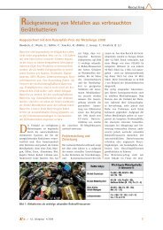
Jaroni, Lucht, Rombach, FriedrichFigure 7:Divided scrap sample after pyrolysis experimentThe figure above shows contrary to the first visual assessment <strong>in</strong> Figure 6, that the entire organicamount is not pyrolysed completely. The dark pa<strong>in</strong>t residues <strong>in</strong>side the block are clearly visible.Which occurs <strong>in</strong> Figure 7 is <strong>in</strong>dicated by white mark<strong>in</strong>gs. It can be seen that the rema<strong>in</strong><strong>in</strong>g organicresidues are not evenly distributed across the block.Especially <strong>in</strong> the lower block layers, carbon material is still present. This fact decrease slightly tothe block centre. The sections 5 and 6 show a completely pyrolysed edge. At the surface layer 4,two block pieces lie on top <strong>of</strong> each other. Thus, there is a very good accessibility <strong>of</strong> the furnaceatmosphere <strong>in</strong> the block centre, result<strong>in</strong>g <strong>in</strong> a high removal <strong>of</strong> organics. Only <strong>in</strong> the centre <strong>of</strong> thislayer organic residues could be detected. On layers 1 to 3 with<strong>in</strong> the centre area, low retentionamounts <strong>of</strong> organic residues are found. The basic cause <strong>for</strong> the different pyrolysis grades <strong>in</strong>different scrap block areas is the gas flow between scrap layers. Although these scrap block sampleshave two open sides as a result <strong>of</strong> cutt<strong>in</strong>g the gas flow between the layers is not homogenous. It canbe assumed that these effects are <strong>in</strong> the <strong>in</strong>dustrial process even higher as a result <strong>of</strong> block geometryand closed block structure.Figure 8 shows a concentration over time diagram <strong>of</strong> the <strong>in</strong>vestigated gas components CO, CO 2 , O 2and C total . This represents the results <strong>of</strong> the experiment 18, which is conducted with an oxygenconcentration <strong>of</strong> 1 %. For a more detailed study the concentration curves are divided over thereaction time <strong>in</strong> three phases: start-, reaction- and “diffusion-phase”. The concept <strong>of</strong> diffusion is notto be understood accord<strong>in</strong>g to its chemical def<strong>in</strong>ition, but rather should be made clear that organicmaterial from <strong>in</strong>side the block take part at pyrolysis reactions with a certa<strong>in</strong> time delay. With<strong>in</strong> thisphase, the organic material at the block surface is already completely pyrolysed, consequently onlyorganic material from the <strong>in</strong>ner block takes part <strong>in</strong> this reaction step. These components must firstleak from <strong>in</strong>side the block so that the shown decrease <strong>of</strong> concentration <strong>of</strong> CO, CO 2 can beexpla<strong>in</strong>ed. The transport <strong>of</strong> the organic compounds from the centre <strong>of</strong> the block is not completedwith<strong>in</strong> the trial period. There<strong>for</strong>e, organic components rema<strong>in</strong> <strong>in</strong>side the block.8Proceed<strong>in</strong>gs <strong>of</strong> EMC 2011
<strong>Conditions</strong> <strong>of</strong> <strong>Pyrolythic</strong> <strong>Processes</strong> <strong>in</strong> <strong>Multi</strong> <strong>Chamber</strong> <strong>Furnaces</strong> <strong>for</strong> Alum<strong>in</strong>ium Recycl<strong>in</strong>gFigure 8:Typical concentration diagram dur<strong>in</strong>g a pyrolysis experimentThe addition <strong>of</strong> the pa<strong>in</strong>ted alum<strong>in</strong>um block can be recognized <strong>in</strong> the first 3 m<strong>in</strong>utes <strong>in</strong> Figure 8.This expla<strong>in</strong>s the <strong>in</strong>crease <strong>of</strong> oxygen concentration, dur<strong>in</strong>g this short time the reactor lid is opened<strong>for</strong> charg<strong>in</strong>g and false air is enter<strong>in</strong>g the reactor. After reseal<strong>in</strong>g <strong>of</strong> the system from the ambientatmosphere the oxygen content drops to default 1.0 % O 2 . The addition <strong>of</strong> scrap can be detected bya sharp <strong>in</strong>crease <strong>of</strong> CO, CO 2 and C total after a delay <strong>of</strong> one m<strong>in</strong>ute. The transition is def<strong>in</strong>ed <strong>in</strong> thereaction phase. The delay is due to the <strong>in</strong>ertia <strong>of</strong> the measur<strong>in</strong>g systems. Dur<strong>in</strong>g the reaction phasethe concentration maxima <strong>of</strong> the studied carbon components are recognized, the maximum level is aresult <strong>of</strong> the exist<strong>in</strong>g oxygen concentration. Especially the course <strong>of</strong> the CO concentration showscharacteristics with<strong>in</strong> the reaction phase. After n<strong>in</strong>e m<strong>in</strong>utes a temporary weaken<strong>in</strong>g <strong>of</strong> theconcentration can be realized. Furthermore, the curve shows two local maxima after about15 m<strong>in</strong>utes, followed by a sharp drop <strong>of</strong> the CO concentration. Such irregularities can be passed atthe beg<strong>in</strong>n<strong>in</strong>g <strong>of</strong> the evaporation <strong>of</strong> other organics conta<strong>in</strong>ed <strong>in</strong> the pa<strong>in</strong>t. These substances have ahigher thermal stability, so that the pyrolysis <strong>of</strong> these materials is delayed. In a weaker <strong>for</strong>m, thisconcentration sequence can also be found <strong>for</strong> CO 2 and C total concentration.Proceed<strong>in</strong>gs <strong>of</strong> EMC 2011 9
Jaroni, Lucht, Rombach, Friedrich5 ConclusionThe aim <strong>of</strong> the pyrolysis experiments, to transfer the pyrolysis conditions from an <strong>in</strong>dustrialchamber furnace to a lab-scale experiment and then to derive optimized the carbon decompositionconditions with modified atmospheres could be achieved <strong>in</strong> large parts <strong>of</strong> this work. Furthermore,the detected CO concentration pr<strong>of</strong>iles can be <strong>in</strong>ferred from at least two other delayed reactions.This fact can be attributed to the different thermal stability with<strong>in</strong> the organic components that donot participate to reach the required activation energy to the reaction. These observations can beconfirmed by the evaluated CO 2 concentration pr<strong>of</strong>iles.Consider<strong>in</strong>g weight loss the used scrap blocks have an average loss between 1.9 to 2.5 % <strong>for</strong>pa<strong>in</strong>ted scrap and 0.7 % oil-conta<strong>in</strong><strong>in</strong>g material. This weight loss is <strong>in</strong>dependent <strong>of</strong> the oxygen supplyand the detected concentration gradients. There is no impact to identify between the ratio <strong>of</strong>combustion, gasification and pyrolysis reaction respectively the oxygen number.Such a statement leads to a contradiction, with <strong>in</strong>creas<strong>in</strong>g oxygen supply, the measured CO andCO 2 concentrations <strong>in</strong>creases sharply and there<strong>for</strong>e an <strong>in</strong>creased weight loss would be expected.This contradiction can be expla<strong>in</strong>ed by the build<strong>in</strong>g <strong>of</strong> short-cha<strong>in</strong> hydrocarbon compounds at lowO 2 concentrations, which are not detected by the used <strong>in</strong>struments.The current work shows that <strong>for</strong> the <strong>in</strong>dustrial multi chamber furnace process common charg<strong>in</strong>gtime <strong>for</strong> <strong>of</strong> round about 30 m<strong>in</strong> to <strong>in</strong>crease the furnace output is too short <strong>for</strong> a complete pyrolysisprocess <strong>of</strong> baled th<strong>in</strong> sheet or foil scrap. The experimental work shows that the <strong>in</strong>terval currently <strong>in</strong>use is not long enough to complete the pyrolysis <strong>of</strong> organic substances, which stick to the alum<strong>in</strong>umscrap. Co<strong>in</strong>cidentally, the pyrolysis experiments show a maximum emission po<strong>in</strong>t after 15 m<strong>in</strong>utesresidence time <strong>in</strong> the pyrolysis reactor. In the follow<strong>in</strong>g 15 m<strong>in</strong>utes, a significant reduction <strong>of</strong> the<strong>in</strong>vestigated carbon compounds is observed, but not to the end <strong>of</strong> the reactions. This fact can besubstantiated by an <strong>in</strong>vestigation <strong>of</strong> the scrap material after 30 m<strong>in</strong>utes <strong>of</strong> pyrolysis that showsresidues <strong>of</strong> organic close to the centre block regions.The previously described situation leads to two consequences <strong>for</strong> the production <strong>of</strong> recycledalum<strong>in</strong>um <strong>in</strong> two-chamber furnaces. First, not all <strong>of</strong> the calorific value <strong>of</strong> the organic materialadher<strong>in</strong>g to the scrap will be used <strong>for</strong> the remelt<strong>in</strong>g process, s<strong>in</strong>ce the residence time is notsufficient <strong>for</strong> this purpose. Thus, there is an <strong>in</strong>creased natural gas consumption, which <strong>of</strong>fset theamount not recovered pyrolysis. As a second consequence <strong>of</strong> the <strong>in</strong>complete pyrolysis, the carbon<strong>in</strong>put <strong>in</strong>to the alum<strong>in</strong>um melt and the subsequent carbide <strong>for</strong>mation is <strong>in</strong>creas<strong>in</strong>g. This entry can bereduced by cont<strong>in</strong>ued pyrolysis. A reduction <strong>in</strong> carbon entry will have positive effects on the purity<strong>of</strong> the obta<strong>in</strong>ed secondary alum<strong>in</strong>um and reduce the <strong>in</strong>efficient <strong>for</strong>mation <strong>of</strong> dross.10Proceed<strong>in</strong>gs <strong>of</strong> EMC 2011
<strong>Conditions</strong> <strong>of</strong> <strong>Pyrolythic</strong> <strong>Processes</strong> <strong>in</strong> <strong>Multi</strong> <strong>Chamber</strong> <strong>Furnaces</strong> <strong>for</strong> Alum<strong>in</strong>ium Recycl<strong>in</strong>g6 OutlookIn order to understand the distribution <strong>of</strong> carbon impact with<strong>in</strong> the streams <strong>of</strong> a multi chamberfurnace more precisely, further <strong>in</strong>vestigations will be carried out. The focus will be on determ<strong>in</strong><strong>in</strong>greal carbon mass flow through the dross and the recycled alum<strong>in</strong>um. In addition, the effects on meltpurity and the amount <strong>of</strong> dross <strong>for</strong>mation caused by the rema<strong>in</strong><strong>in</strong>g carbon content on the scrap willbe <strong>in</strong>vestigated. The current work shows that the pyrolysis process is still runn<strong>in</strong>g when the scrapblock is pushed under the melt. It is assumed that <strong>for</strong>med gases have a long contact time <strong>in</strong>side themelt. This gas/liquid reaction will <strong>in</strong>crease the dross <strong>for</strong>mation. A longer pyrolysis time couldprevent these effects. To separate these effects gas <strong>in</strong>jections experiments are runn<strong>in</strong>g to <strong>in</strong>vestigatethe <strong>in</strong>fluence <strong>of</strong> different pyrolysis gaseous products <strong>in</strong> alum<strong>in</strong>um melts.However, to f<strong>in</strong>d the best way between complete trans<strong>for</strong>mation <strong>of</strong> organic material <strong>in</strong>to furnaceatmosphere and a high furnace per<strong>for</strong>mance is the challenge.AcknowledgementThe authors would like to thank the Hydro Alum<strong>in</strong>ium Rolled Products GmbH <strong>for</strong> fund<strong>in</strong>g thestudies and provid<strong>in</strong>g scrap material <strong>for</strong> trails and <strong>for</strong> their analytical support.References[1] KALTSCHMITT, M., HARTMANN, H., HOFBAUER, H., Energie aus Biomasse – Grundlagen,Techniken, Verfahren, Spr<strong>in</strong>ger Verlag Berl<strong>in</strong>, Heidelberg, 2001, korrigierter Nachdruck2009, ISBN: 978-3-540-85094-6, 2. Auflage.[2] RUMPEL, S., Die autotherme Wirbelschichtpyrolyse zur Erzeugung heizwertreicher Stützbrennst<strong>of</strong>fe,Universität Karlsruhe (TH), Dissertation, 2000.[3] SCHMITZ, C. Handbook <strong>of</strong> Alum<strong>in</strong>ium Recycl<strong>in</strong>g, Vulkan Verlag 2006,ISBN 978-3-8027-2936-2.[4] MEIER, D., FAIX, O., Heizöl und Chemie-Rohst<strong>of</strong>fe aus Holz – Flash-Pyrolyse eröffnet neueMöglichkeiten, <strong>in</strong>: Forschungs-Report Heft 1, S. 38-41, 1999.[5] EPPLE, B., LEITHNER, R., LINZER, W., WALTER, H., Simulation von Kraftwerken und wärmetechnischenAnlagen, Spr<strong>in</strong>ger Verlag Wien, New York, 2009, ISBN: 978-3-211-29695-0.Proceed<strong>in</strong>gs <strong>of</strong> EMC 2011 11
Jaroni, Lucht, Rombach, Friedrich12Proceed<strong>in</strong>gs <strong>of</strong> EMC 2011