Conditions of Pyrolythic Processes in Multi Chamber Furnaces for ...
Conditions of Pyrolythic Processes in Multi Chamber Furnaces for ...
Conditions of Pyrolythic Processes in Multi Chamber Furnaces for ...

You also want an ePaper? Increase the reach of your titles
YUMPU automatically turns print PDFs into web optimized ePapers that Google loves.
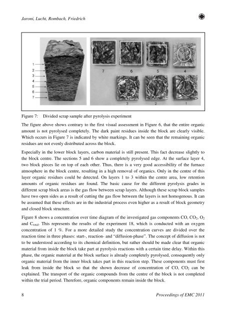
Jaroni, Lucht, Rombach, FriedrichFigure 7:Divided scrap sample after pyrolysis experimentThe figure above shows contrary to the first visual assessment <strong>in</strong> Figure 6, that the entire organicamount is not pyrolysed completely. The dark pa<strong>in</strong>t residues <strong>in</strong>side the block are clearly visible.Which occurs <strong>in</strong> Figure 7 is <strong>in</strong>dicated by white mark<strong>in</strong>gs. It can be seen that the rema<strong>in</strong><strong>in</strong>g organicresidues are not evenly distributed across the block.Especially <strong>in</strong> the lower block layers, carbon material is still present. This fact decrease slightly tothe block centre. The sections 5 and 6 show a completely pyrolysed edge. At the surface layer 4,two block pieces lie on top <strong>of</strong> each other. Thus, there is a very good accessibility <strong>of</strong> the furnaceatmosphere <strong>in</strong> the block centre, result<strong>in</strong>g <strong>in</strong> a high removal <strong>of</strong> organics. Only <strong>in</strong> the centre <strong>of</strong> thislayer organic residues could be detected. On layers 1 to 3 with<strong>in</strong> the centre area, low retentionamounts <strong>of</strong> organic residues are found. The basic cause <strong>for</strong> the different pyrolysis grades <strong>in</strong>different scrap block areas is the gas flow between scrap layers. Although these scrap block sampleshave two open sides as a result <strong>of</strong> cutt<strong>in</strong>g the gas flow between the layers is not homogenous. It canbe assumed that these effects are <strong>in</strong> the <strong>in</strong>dustrial process even higher as a result <strong>of</strong> block geometryand closed block structure.Figure 8 shows a concentration over time diagram <strong>of</strong> the <strong>in</strong>vestigated gas components CO, CO 2 , O 2and C total . This represents the results <strong>of</strong> the experiment 18, which is conducted with an oxygenconcentration <strong>of</strong> 1 %. For a more detailed study the concentration curves are divided over thereaction time <strong>in</strong> three phases: start-, reaction- and “diffusion-phase”. The concept <strong>of</strong> diffusion is notto be understood accord<strong>in</strong>g to its chemical def<strong>in</strong>ition, but rather should be made clear that organicmaterial from <strong>in</strong>side the block take part at pyrolysis reactions with a certa<strong>in</strong> time delay. With<strong>in</strong> thisphase, the organic material at the block surface is already completely pyrolysed, consequently onlyorganic material from the <strong>in</strong>ner block takes part <strong>in</strong> this reaction step. These components must firstleak from <strong>in</strong>side the block so that the shown decrease <strong>of</strong> concentration <strong>of</strong> CO, CO 2 can beexpla<strong>in</strong>ed. The transport <strong>of</strong> the organic compounds from the centre <strong>of</strong> the block is not completedwith<strong>in</strong> the trial period. There<strong>for</strong>e, organic components rema<strong>in</strong> <strong>in</strong>side the block.8Proceed<strong>in</strong>gs <strong>of</strong> EMC 2011