Conditions of Pyrolythic Processes in Multi Chamber Furnaces for ...
Conditions of Pyrolythic Processes in Multi Chamber Furnaces for ...
Conditions of Pyrolythic Processes in Multi Chamber Furnaces for ...

Create successful ePaper yourself
Turn your PDF publications into a flip-book with our unique Google optimized e-Paper software.
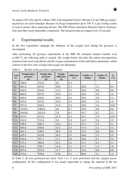
Jaroni, Lucht, Rombach, FriedrichTo analyse CO, CO 2 and O 2 a B<strong>in</strong>os 1001 with <strong>in</strong>tegrated Oxynos 100 and a X-am 7000 gas analys<strong>in</strong>gdevices are used redundant. Because <strong>of</strong> <strong>of</strong>f-gas temperatures up to 350 °C a gas cool<strong>in</strong>g systemis used to protect these analys<strong>in</strong>g devices. The FID (Flame Ionization Detector) detects hydrocarbonsand other easily flammable components. The measured data are logged every 10 seconds.4 Experimental resultsIn the first experiment campaign the <strong>in</strong>fluence <strong>of</strong> the oxygen level dur<strong>in</strong>g the pyrolysis is<strong>in</strong>vestigated.After per<strong>for</strong>m<strong>in</strong>g 20 pyrolysis experiments <strong>in</strong> the IME lift resistance heated crucible ovenat 600 °C, the follow<strong>in</strong>g table is created. The weight be<strong>for</strong>e and after the carbon decompositionreaction <strong>of</strong> the used scrap blocks and the oxygen concentration <strong>of</strong> the <strong>in</strong>dividual experiments, whichconsists <strong>of</strong> the flow rates <strong>of</strong> argon and oxygen are illustrated.Table 2:Results <strong>of</strong> the pyrolysis experimentsTrailNo.Weight be<strong>for</strong>epyrolysis[g]Weight afterpyrolysis[g]Weightdifference[g]Difference[%]Gasflow Ar[l/m<strong>in</strong>]Gasflow O 2[l/m<strong>in</strong>]V1 340.0 332.0 8.0 2.4 - - -V2 861.0 841.0 20.0 2.3 20.0 1.2 0.4V3 845.0 824.0 21.0 2.5 20.0 0.0 0.0V4 866.0 847.0 19.0 2.2 20.0 2.0 3.4V5 848.0 828.0 20.0 2.4 20.0 2.0 3.4V6 842.0 823.0 19.0 2.3 20.0 1.5 1.0V7 857.0 836.0 21.0 2.5 20.0 2.6 10.0V8 1076.0 1068.0 8.0 0.7 20.0 0.0 0.0V9 1019.0 1012.0 7.0 0.7 18.7 0.7 2.2V10 833.0 812.0 21.0 2.5 18.2 2.9 10.0V11 542.8 533.0 9.8 1.8 16.5 2.6 2.5V12 598.8 586.2 12.6 2.1 15.2 1.5 2.1V13 563.8 550.6 13.2 2.3 17.4 2.1 3.3V14 561.4 550.9 10.5 1.9 14.5 0.0 0.0V15 425.5 415.0 10.5 2.5 16.6 2.1 2.5V16 542.8 531.7 11.1 2.0 16.6 2.1 2.4V17 577.2 564.9 12.3 2.1 17.7 2.2 3.1V18 562.5 550.7 11.8 2.1 17.7 1.9 1.0V19 567.6 555.9 11.7 2.1 14.6 0.0 0.0V20 572.6 559.6 13.0 2.3 20.0 3.1 1.2In Table 2, all tests per<strong>for</strong>med are listed. Tests 1 to 11 were per<strong>for</strong>med with the orig<strong>in</strong>al reactorconfiguration. In this configuration it was nearly impossible to charge the material <strong>in</strong> the hotO 2[%]6Proceed<strong>in</strong>gs <strong>of</strong> EMC 2011