LPG Products Catalogue - Cross Technical Services
LPG Products Catalogue - Cross Technical Services
LPG Products Catalogue - Cross Technical Services

Create successful ePaper yourself
Turn your PDF publications into a flip-book with our unique Google optimized e-Paper software.
The complete range of<strong>LPG</strong> essentialsFlüssiggas-Anlagen GmbH • Peiner Straße 217 • D - 38229 Salzgitter (Germany)Tel. +49 (0) 53 41 / 86 97-0 • Fax +49 (0) 53 41 / 86 97-11E-Mail: info@fas-uni.de • http://www.fas-uni.de
Company Profile of FAS-GermanyThe company FAS, Flüssiggas-Anlagen GmbH Salzgitter, was established in 1975 ascommercial enterprise for <strong>LPG</strong> equipment (propane / butane). At the end of the seventies the„safety idea“ gained more and more acceptance for customers and users. Due to the legalrules and regulations FAS extended the product range „safety engineering“ and included alarge number of further valves, fittings and equipment into the delivery program in order tocomply with the increased requirements in safety engineering of gas producers, suppliersand distributors.Over the years new products were developed and constructed by FAS for market niches inorder to be able to fulfill the increasing wishes and requirements of the customers.For this reason it wasalso necessary tochange and to extendthe production area inSalzgitter a few timesso that now in the newlocation in Salzgitter /Peiner Straße 217 thepossiblity to come upto the actual marketsituation is given andrealized.FAS possesses modern and large-scale production facilities with a service workshop andis able to produce all innovative FAS-products in highest possible quality and in a reliablemanner under observation of the delivery dates.The products developed by FAS are manufactured on most modern machines by highlyqualified and efficient experts and are subject to a very extensive quality securing system.Due to the far-sighted and successful company politics FAS purposefully developed toone of the most competitive and efficient suppliers of <strong>LPG</strong> fittings and equipment for road tankersand stationary installations within Europe.The company may fall back upon one of the best assorted and largest stock of equipmentsof any kind destined for all industrial <strong>LPG</strong> applications within Europe. With more than 10.000of different articles on stock, FAS has one of the widest assortments of this branch worldwide.In the meantime FAS is represented on almost all important markets within Europe by itsown sister companies, by local sales consultants or agencies.As certified company with a process-orientated managementsystem according to DIN EN ISO 9001:2008 FAS delivers all productsand services according to the Pressure Equipment Directive 97/23/EC,ATEX 94/9/EC, MID 2004/22/EC, OIML, TÜV, PTB etc. with CE-mark.
<strong>Products</strong> and ActivitiesAutogas Filling StationTerminalFilling StationCalibration StationProductionDispenserVaporizerWarehouseCompressor UnitAfter SalesServiceValves and FittingsPump Unit“Turn Key”ProjectsLoading Arm StationComplete Filling PlantCylinder FillingStationComplete Packagefor Road TankersLoading andUnloading PlantFlüssiggas-Anlagen GmbHPeiner Straße 217D-38229 Salzgitter(Germany)Phone +49 (0) 53 41 / 86 97-0Fax +49 (0) 53 41 / 86 97-11E-mail info@fas.deWebsite www.fas.deFAS 29647-05/09
FAS is presented in all important markets within Europe and in some marketsworld-wide by own branches, local consultants and authorized representatives.Certified according to- DIN EN ISO 9001:2008- PED 97/23/EC- ATEX 94/9/EC- MID 2004/22/EC- TPED 99/36/ECAs certified company with a process-orientated management system according toDIN EN ISO 9001:2008 FAS delivers all products and services according to thePressure Equipment Directive 97/23/EC (Module H and H1), ATEX, MID, OIML, TÜV, PTB etc.with CE-mark as basis for quality, highest possible product safety and reliability.Flüssiggas-Anlagen GmbH • Peiner Straße 217 • D-38229 Salzgitter • GermanyPhone +49 (0) 5341 / 8697-0 • Fax +49 (0) 5341 / 8697-11E-Mail info@fas.de • Website www.fas.deFAS KarteFAS2011Rev.01
CERTIFICATEThe Certification Bodyof TÜV SÜD Management Service GmbHcertifies thatFlüssiggas-Anlagen GmbHPeiner Str. 217, D-38229 Salzgitterhas established and appliesa Quality Management System forDevelopment, Manufacturing, Sales and Service for<strong>LPG</strong>-EquipmentAn audit was performed, Report No. 70025248Proof has been furnished that the requirementsaccording toISO 9001: 2008are fulfilled. The certificate is valid until 2011-07-14Certificate Registration No. 12 100 16484/01 TMSMunich, 2009-04-02QMS-TGA-ZM-07-92
We are Members of:Deutschen Verband Flüssiggas e.V.WORLD LP GAS ASSOCIATION
Convince yourself of ouradvantages !Following aspects will make your decision easier:• Best possible cost-performance ratio• Low operation and maintenance cost• 2 Quality Management Systems:DIN EN ISO 9001:2000 and PED 97/23/EC• ATEX-approval 94/9/EC• Long service life - Made in Germany• Execution for 24-h-operation with fleet cardsand EC-cards, respectively credit cardsystems• Connection to all common point-of-salessystems• KNOW HOW of more than 30 yearsin the field of planning, engineeringand construction of <strong>LPG</strong> dispensersand AUTOGAS filling stations• Complete dispenser technology• Watertight and weatherproofelectronic head• High precision and accuracy• Production of your individual dispenserand filling station• Modern designFAS is the only manufacturerthat produces all essentialcomponents in Germany,among othes housing, pistonmeter etc. With more than10.000 manufactured dispensersFAS has worldwide references !Your AUTOGAS filling stationof FAS is your businesscard!Flüssiggas-Anlagen GmbHPeiner Straße 217D-38229 Salzgitter(Germany)Certified according to- DIN EN ISO 9001:2000- PED 97/23/EC- ATEX 94/9/ECPhone +49 (0) 53 41 / 86 97-0Fax +49 (0) 53 41 / 86 97-11E-mail info@fas.deWebsite www.fas.deFAS 29695-09/08
Flüssiggas-Zapfsäulen undkomplette AUTOGAS-Tankstellen<strong>LPG</strong>-Dispensers and completeAUTOGAS Filling StationsDie Firma FAS Flüssiggas-Anlagen GmbH, Salzgitter, ist seit 1975 europaweit einer derführenden Hersteller und Lieferanten von Flüssiggas-Armaturen und Anlagenkomponentenfür die Lagerung, Umfüllung und den Transport von Propan / Butan.Als leistungsstarker Partner auf hohem Qualitätsniveau liefert FAS alle wesentlichenKomponenten für Straßentankwagen und stationäre Anlagen, z.B. Armaturen für Rohrleitungen,Ventile für Behälter, Pumpen- und Kompressorstationen, Zähler und Messanlagen,Verladearmstationen und Flaschen-Abfüllanlagen, Verdampfer, Sicherheitstechnik, sowieZapfsäulen und komplette Tankstellen.Als deutscher Hersteller von Flüssiggas-Zapfsäulen bieten wir bestmögliche Qualität, kurzeLieferzeiten, wettbewerbsfähige Preise, individuelle Lösungen, technische Unterstützung undlangjährige Erfahrung bei einem günstigen Betriebs-Kostenverhältnis unserer Ausrüstungsteile.Alle Produkte werden unter Zugrundelegung der DIN EN ISO 9001:2000 gefertigt, mit CE gekennzeichnetund erfüllen die internationalen Normen DGRL 97/23/EG, ATEX, OIML, TÜV, PTB etc.Since 1975 the company FAS Flüssiggas-Anlagen GmbH, Salzgitter, is one of the leadingmanufacturers and suppliers of <strong>LPG</strong> fittings and components for complete stations for thestorage, filling and for the transport of propane / butane within Europe.As your efficient partner on a high standard we supply all essential components for tank trucksand stationary plants, e.g. fittings for pipelines, valves for tanks, pumps and compressor units,meters and metering systems, loading arms stations and cylinder filling plants, vaporizers,safety equipment, engineering, as well as dispensers and complete filling stations.As German manufacturer of <strong>LPG</strong> dispensers we offer best possible quality, short delivery time,competitive prices, individual solutions, technical support and many years of experience andabove all a favourable operating cost ratio of our components.All products are manufactured on the basis of the DIN EN ISO 9001:2000, marked with CEand fulfil the international norms PED 97/23/EC, ATEX, OIML, TUV, PTB etc.Planung, Fertigung, Lieferung und Montage vonkompletten AUTOGAS-Tankstellen einschließlichober- oder unterirdischer Lagerbehälter, mitPumpenanlage, Steuerung und allen erforderlichenSicherheitsarmaturen nach den jeweiligen lokalenVorschriften und Richtlinien.Engineering, production, supply and installation ofcomplete AUTOGAS filling stations includingabove or underground storage tanks with pumpunits, control box and all required safety fittingsaccording to the respective local rules andregulations.Kompaktanlage mit mehreren oberirdischenBehältern und einer elektronischen Zapfsäule, TypFAS-220 in Sonderausführung mit Elektronik passendfür Kassensystem, sowie lackiertem Zapfsäulengehäuseder jeweiligen Mineralölgesellschaft,komplett anschlussfertig geliefert und montiert.Compact skid-mounted autogas filling station withseveral aboveground tanks and one electronicdispenser, type FAS-220 in special execution withelectronics suitable for “point of sales system”, aswell as lacquered dispenser housing of the desiredoil company, delivered and installed completelyready for connection.
FAS-Zapfsäulen-ModelleDifferent types of <strong>LPG</strong>-dispensersAlle elektronischen Zapfsäulen werden in einem Edelstahlgehäuse mit entsprechenden Prüf- undTestzertifikaten geliefert. Auf Wunsch erfolgt die Fertigung mit Lackierung und Design der jeweiligenMineralölgesellschaft, sowie mit angepasster Elektronik für die vorhandenen Kassensysteme.All electronic dispenser are delivered in a stainless steel housing with corresponding test certificates. Onrequest the production is executed with painting and design of the respective oil company, as well aswith suitable electronic computer for the existing „point of sales systems“.Für folgende Benzin-/ Diesel-Zapfsäulen können Anpassungen geliefert werden: Tankanlagen Salzkotten,Gilbarco, Scheidt + Bachmann, Wayne Dresser, Tokheim und Schlumberger. Andere Systeme auf Anfrage.For following petrol / diesel dispensers corresponding adaptations can be supplied: Tankanlagen Salzkotten,Gilbarco, Scheidt + Bachmann, Wayne Dresser, Tokheim and Schlumberger. Other systems on request.Elektronische Zapfsäule, Typ FAS-220 (mit einemSchlauch) und Typ FAS-230 (mit zwei Kolbenzählern undzwei Schläuchen), Leistung 5-50 l/min., Zapfpistolen nachSpezifikation, gegen Mehrpreis mit TVC, Preset etc. verfügbar.Electronic dispenser, type FAS-220, (with one hose) andtype FAS-230 (with two piston meters and two hoses),capacity 5-50 l/min, dispenser nozzles according to specification,against extra charge available with TVC, preset etc.Typ FAS-230Typ FAS-420-LElektronische Kleinzapfsäule, Typ FAS-120, mit einemSchlauch, mit einem oder zwei Displays, ohneSchlauchrückholsystem. Technische Ausführung wieTyp FAS-220.Compact electronic dispenser, type FAS-120, with onehose, with one or two displays, without hose return system.<strong>Technical</strong> execution like type FAS-220.Elektronische Zapfsäule mit Tankautomat, Typ FAS-420 L,(Kundenkartensystem) und Typ FAS-420 L-EC (EC-Kreditkartensystem).Electronic dispenser with card system, type FAS-420 L,(customer card system) and type FAS-420 L-EC(EC-card system).Elektronische Zapfsäule, Typ FAS-130, mit und ohneZählwerk, vor allem geeignet für interne Betankungen(z.B. Gabelstapler, Flottenfahrzeuge etc).Electronic dispenser, type FAS-130, with and withoutmeter, suitable above all for internal refuelling processes(e.g. fork lift trucks, fleet vehicles etc).Typ FAS-120Typ FAS-130Sondermodelle - Integration in vorhandene Tankstellendesigns und Kassensysteme
Tankstellen-Varianten mit oberirdischem BehälterDifferent filling stations with aboveground tanksNutzen Sie unsere 30-jährige Erfahrung bei der Planung, Lieferung, Montage, Inbetriebnahme und Wartungvon Tank- und Füllanlagen für Flüssiggas.Take advantage of our 30 years of experience for the construction, supply, installation, commissioning andmaintenance of tank and filling stations for <strong>LPG</strong>.FAS-Produkte zeichnen sich vor allem durch modernesDesign nach neuestem Stand der Technik,Langlebigkeit bei niedrigen Wartungs- undReparaturkosten, Qualität und hohenSicherheitsstandard, sowie ein gutes Preis-Leistungsverhältnis aus.Some of the remarkable features of FAS-productsare the modern design according to the state-of-thearttechnology, long life with inferior maintenanceand repair costs, quality and a high safety degree, aswell as a good cost/performance-ratio.Die Ausführungen und Aufbauvarianten werdennach länderspezifischen Richtlinien, Vorschriften undKundenanforderungen ausgeführt und können alsBaukastensystem nach Bedarf kombiniert werden.The different executions and mounted versionsare effected according to the particulars and specificregulations of the different countries and may becombined as modular construction on request.Als kostengünstige Varianten gelten unsere steckerfertigenKompaktanlagen mit Standsäule oder mitSteuerung im Zapfsäulenkopf, mit oder ohneZählwerk, Typ FAS-130, zur Betankung vonBallonflaschen, Gabelstaplern und Flottenfahrzeugen.Favourable solutions are our compact systems withstand column or with control system in dispenserhead, with or without liter counter, type FAS-130which are ready for connection and destined for therefuelling process of balloon cylinders, forklifts andfleet vehicles.Flüssiggas-Tankstelle als Kompaktanlage mit oberirdischem Behälter und Druckerhöhungspumpe, komplettmit Zapfsäule nach Kundenwunsch und mit Wetterschutzdach, komplett mit allen Sicherheitsarmaturenauf einem verzinkten Grundrahmen montiert.<strong>LPG</strong> filling station as compact system with aboveground tank and pressure increasing pump, complete withdispenser according to customer request and with weather protection roof, complete with all safety fittingsmounted on a galvanized frame.
Tankstellen-Varianten mit unterirdischem BehälterDifferent filling stations with underground tanksAls einer der größten Hersteller in Europa bietetFAS eine Vielzahl von Aufbauvarianten undAusführungen nach länderspezifischen Vorgabenund Vorschriften. Die Flüssiggas-Zapfsäulen undTankstellen sind mit den erforderlichen Zulassungenund Zertifikaten lieferbar.As one of the largest manufacturers in EuropeFAS offers a variaty of different versions and executionsaccording to the particulars and specificregulations of the different countries. The <strong>LPG</strong>dispensers and filling stations are available withthe required approvals and certificates.FAS liefert komplette <strong>LPG</strong>-Tankstellen mit unterirdischen Lagerbehälterneinschließlich Pumpeneinheit und Zapfsäule imTankstellendesign, anschlussfertig für die jeweiligen Kassensysteme.Alle erforderlichen Armaturen und Ausrüstungskomponenten werdenim Domschacht montiert, verrohrt, grundiert und lackiert.FAS supplies complete <strong>LPG</strong> filling stations with underground storagetanks including pump unit and dispenser in petrol station design,ready for connection to the respective point-of-sales systems. Allnecessary fittings and components of equipment are installed in thedome pit, tubed, primed and lacquered.Zwei unterschiedliche Pumpensysteme mit allen erforderlichenSicherheitsarmaturen stehen den Kunden zur Auswahl:• Tauchpumpe mit Ex-Motor und Schleuse als komplette Einheitzum direkten Einbau in die Flüssigphase des Behälters:FAS-Nr. 21583: max ∆p 9 bar, Leistung ca. 50 l/min bei ∆p 8 barFAS-Nr. 21584: max ∆p 11 bar, Leistung ca.130 l/min bei ∆p 8 bar• Saugpumpeneinheit mit Ex-Motor, komplett montiert auf Grundrahmenzum Einbau außerhalb des Behälters:FAS-Nr. 21606: max ∆p 12 bar, Leistung ca. 50 l/min bei ∆p 8 barFAS-Nr. 21607: max ∆p 10 bar, Leistung ca. 100 l/min bei ∆p 8 barFAS-Nr. 21618: max ∆p 12 bar, Leistung ca. 250 l/min bei ∆p 8 barThere are two different pumps systems with all required safety fittings to choose from:• Submersible pump with ex-motor and manifoldas complete unit for direct installation into liquidphase of tank:FAS-No. 21583:max ∆p 9 bar, capacity approx. 50 l/min with ∆p 8 barFAS-No. 21584:max ∆p 11 bar, capacity approx.130 l/min with ∆p 8 bar• Suction pump system with ex-motor, completelyassembled on a base frame for installationoutside of tank:FAS-No. 21606:max ∆p 12 bar, capacity approx. 50 l/min with ∆p 8 barFAS-No. 21607:max ∆p 10 bar, capacity approx. 100 l/min with ∆p 8 barFAS-No. 21618:max ∆p 12 bar, capacity approx. 250 l/min with ∆p 8 barFlüssiggas-Anlagen GmbHPeiner Straße 217D-38229 Salzgitter(Germany)Phone +49 (0) 53 41 / 86 97-0Fax +49 (0) 53 41 / 86 97-11E-mail info@fas.deWebsite www.fas.deFAS 29131-03/07
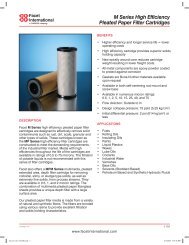
Autogas Filling Stations and <strong>LPG</strong> Dispensers:Modern design and reliable and proven product qualityThe Autogas FillingStation of FAS is yourbusiness card!Samples of AutogasFilling Stationsinstalled in Germany- 35 years of experience- Worldwide references- More than 13.000 <strong>LPG</strong>dispensers manufactured- Short delivery times- Certified according toDIN EN ISO 9001:2008- Made in GermanyFlüssiggas-Anlagen GmbHPeiner Straße 217D-38229 Salzgitter(Germany)Phone +49 (0) 53 41 / 86 97-0Fax +49 (0) 53 41 / 86 97-11E-mail info@fas.deWebsite www.fas.de
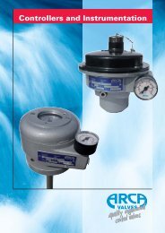
With a KNOW HOW of more than 30 yearsin the field of planning, engineering and construction of <strong>LPG</strong>dispensers and Autogas filling stations, FAS has worldwidereferences with more than 10.000 manufactured dispensersPiston Meter with magnetic coupling:Advantages:- sealless measurement technique- low maintenance operation- high accuracy of measurement- low operation cost- 2 years warranty- on request available in all dispensers, type FASDifferent versions of <strong>LPG</strong> Dispensers, type FAS:Type FAS-420 LType FAS-420 L-ECType FAS-120Advantages of <strong>LPG</strong> dispensers, type FAS:- Complete dispenser technology - High precision and accuracy- Long service life - Made in Germany- Modern design - Low operation and maintenance costType FAS-230Type FAS-230“HIGH MAST”Type FAS-220All FAS-dispenser types are optionally available with hose retraction system, with presetand with temperature volume compensation TVC.Group22FAS-12/10E
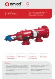
Compact skid mounted<strong>LPG</strong> Cylinder Filling UnitsCertified according toDIN EN ISO 9001:2008FAS supplies all productsaccording to PED 97/23/ECEX-Directive ATEX 94/9/EC,Machinery Directive 06/42/EC,MID 04/22/EC,Declaration of Conformityand CE-markCompact skid mounted <strong>LPG</strong> Cylinder Filling Unit- with electronic filling and control scale for cylinders of size 5, 11 und 33 kg suitable for calibration,control in electric solenoid valve- completely mounted in a painted and lock-up cabinet- mechanical cylinder evacuation unit mit hand pump- aboveground <strong>LPG</strong> storage tank 2,9 t (6400 l)- external pump unit with mechanical seal, capacity approx. 50 l/min,- Electrical switch cabinet and weather protection housing- completely mounted on galvanized baseframeOptions against extra charge:- separate dispenser for autogas- stairs with two steps- weather protection roof (without picture)- Third Party Inspection- freight charges, installation and commissioning- Local approval costExecution with additional dispenser, type FAS 120Versions of installations:FAS also supplies complete cylinderfilling stations with one or severalfilling scales in container version ormanufactures carrousel filling plantswith chain conveyors with several fillingscales in series according to customerrequirements and specification.Flüssiggas-Anlagen GmbHPeiner Straße 217D-38229 Salzgitter(Germany)Telefon +49 (0) 53 41 / 86 97-0Telefax +49 (0) 53 41 / 86 97-11E-Mail info@fas.deWebsite www.fas.deFAS 29 554-09/10
<strong>LPG</strong> Cylinder Filling UnitSmall Compact Container VersionCertified according to DIN EN ISO 9001:2008FAS delivers all products according toPressure Equipment Directive 97/23/EC,ATEX 94/9/EC, MID 04/22/EC,TÜV, PTB etc.with CE-mark.Advantages / Features:- Low investments andlow maintenance cost- Transportable, compactsystem in lock-up container- Reliability, precision, long lifetime- Option for <strong>LPG</strong> cylinders from 2 to 46 kg- Execution with pneumaticor manual evacuation system- Ex-proof electrical execution- All control and safety equipment included- Possibility to compose the system as complete unitwith all required safety fittings- Additionally available with Autogas filling station- Option with stainless steel column of scale (extra charge)Versions:- Execution accordingto specific regulationsof different countries- Execution of systemaccording to customerspecification- System with highercapacities availableon request.Complete Solution:FAS supplies Autogas filling stations in combinationwith <strong>LPG</strong> cylinder filling plants as complete unit.Flüssiggas-Anlagen GmbHPeiner Straße 217D-38229 Salzgitter(Germany)Phone +49 (0) 53 41 / 86 97-0Telefax +49 (0) 53 41 / 86 97-11E-Mail info@fas.deWebsite www.fas.de
Valves and FittingsDuring the past pyears we have also specialized in the development and pro-duction of fittings for the solution of very special problem cases.As manufacturer of niche products we succeeded in finding solutions for individual requirementsof customers and their specified installations. Besides the development of new productswe have executed the improvement, modification and adaptation of components well-establishedfor many years.We can offer the valves and fittings manufactured by us as trade products with tested qualityand certificates. Thus FAS is in the position to supply all necessary and required componentsfor <strong>LPG</strong> installations.FAS-Back PressureCheck valveFAS-Excess Flow ValveFAS-Vapour EliminatorFAS-DifferentialPressure ValveFAS-By-pass ValveFAS-Internal ValveFAS-StrainerFAS-Sight FlowIndicatorFAS-Ball ValveWe succeeded in arranging a long-term co-operation with a smaller, foreign partnerregarding the common production and distribution of fittings. The range of products ofour partnership includes ball valve, strainers, sight flow indicators for a multitude ofindividual application purposes following the DIN ISO EN 9001:2000 and the PressureEquipment Directive 97/23/EC.Flüssiggas-Anlagen GmbHPeiner Straße 217D-38229 Salzgitter(Germany)Phone: +49 (0) 53 41 / 86 97-0Fax: +49 (0) 53 41 / 86 97-11E-mail: info@fas-uni.dehttp: //www.fas-uni.de
FLÜSSIGGAS-KOMPRESSOREN FÜR ALLE ANWENDUNGEN<strong>LPG</strong> COMPRESSORS FOR ALL KIND OF APPLICATIONSStationäres KompressoraggregatStationary Compressor UnitDiesel-KompressoraggregatDiesel Compressor UnitMobiles KompressoraggregatMobile Compressor UnitKompressor für StraßentankwagenCompressor for <strong>LPG</strong> Road TankerDie Kompressoren sind in verschiedenen Varianten und Ausführungen lieferbar.Abhängig vom Anwendungszweck sind folgende Größen verfügbar:Max. Leistung: 26 m 3 /h58 m 3 /h100 m 3 /h200 m 3 /hThe compressors are available in different version and executions.Depending on the application purpose following sizes may be selected:Max. capacity: 26 m 3 /h58 m 3 /h100 m 3 /h200 m 3 /hFlüssiggas-Anlagen GmbHPeiner Straße 217D-38229 Salzgitter(Germany)Phone +49 (0) 53 41 / 86 97-0Fax +49 (0) 53 41 / 86 97-11E-mail info@fas.deWebsite www.fas.de21664FAS-05/07
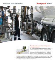
High Performance FAS Pump UnitsThe NZ series pumps offer high capacity capable of reaching upto 260 m3/h at relatively high differential pressure.NEW !NEW !Advantages:- compact construction- unique hydrauliccharacteristics- low energy consumptioneven at high differentialpressures- minimal noise level- eliminated vibration- long service life- low operation costsOption:- Incorporation inmodernization projects ofexisting plants- operation in tandem withother makes of pumpsPower consumption, kW Differential pressure, barCapacity, m3/hrCapacity, m3/hrCertified according to- DIN EN ISO 9001:2008- PED 97/23/EC- ATEX 94/9/ECCapacity, m3/hrCapacity Curvepump type FAS NZ 60-7-20, 2900 min -1Flüssiggas-Anlagen GmbHPeiner Str. 217D -38229 Salzgitter(Germany)Phone +49 53 41 / 86 97-0Fax +49 53 41 / 86 97-11E-mail info@fas.deWebsite www.fas.deFAS29640-06/10Rev.01
Flüssiggas-Anlagen GmbH • Peiner Str. 217 • D-38229 Salzgitter/Germany • Tel. +49 (0) 5341-8697-0 • Fax +49 (0) 5341-8697-11 • www.fas.de • info@fas.de- 2 -
Flüssiggas-Anlagen GmbH • Peiner Str. 217 • D-38229 Salzgitter/Germany • Tel. +49 (0) 5341-8697-0 • Fax +49 (0) 5341-8697-11 • www.fas.de • info@fas.de- 3 -
Flüssiggas-Anlagen GmbH • Peiner Str. 217 • D-38229 Salzgitter/Germany • Tel. +49 (0) 5341-8697-0 • Fax +49 (0) 5341-8697-11 • www.fas.de • info@fas.de- 4 -
Complete side channel pump units for perfect liquid transferto <strong>LPG</strong> filing stations with overground tanksOur Know How is based on 27 years of experience with theapplication of these pump units.Following features distinguish these side channel pump unitsfrom the positive displacement pumps:long lifetime, low noise and low maintenance with inferiorrepair costs.For the application as suction pump unit in combination withunderground tanks an additional retaining stage has to beintegrated into the pump.4 executions for autogas filling stations are available:without retaining stage (for stations with aboveground tanks)- FAS-No. 21 942: capacity up to 50 l/min,differential pressure up to 12 bar, ex-proof motor E Ex e, 3,6 KW- FAS-No. 21 920: capacity up to 100 l/min,differential pressure up to 12 bar, ex-proof motor E Ex e, 6,8 KWwith retaining stage (for stations with underground tanks)- FAS-No. 21 447: capacity up to 50 l/min,differential pressure up to 12 bar, ex-proof motor E Ex e, 5,0 KW- FAS-No. 21 996: capacity up to 100 l/min,differential pressure up to 12 bar, ex-proof motor E Ex e, 6,8 KWwithout retaining stagewith retaining stageAdvantages / Features:- Low noise- Low maintenance- High differential pressure- Continuous operation- Uniform dimensions:Pumps 50 and 100 l/min. have same connections:inlet DN 65, outlet DN 32, with flanges acc. to DIN 2635- High product quality- Many years of experience- ReliabilityFlüssiggas-Anlagen GmbHPeiner Str. 217 • 38229 Salzgitter / GermanyTel. +49 (0) 53 41 / 86 97-0Fax : +49 (0) 53 41 / 86 97-11E-mail: info@fas-uni.dehttp: //www.fas-uni.de
FAS-Vaporizer TechnologyThe FAS-vaporizers suitable for hazardous areas, zone 1 and 2 offera safe and reliable energy supply at an attractive cost-performance ratioNew designin stainless steelexecutionDry-type vaporizer, type FAS 2000• ex-proof• nominal capacity up to 170 kg/h(32 kg/h, 60 kg/h, 100 kg/h, 170 kg/h, 330 kg/h, 450 kg/h)• suitable for installation in zone 2• individual installation orcomplete solution in cabinet constructionAs certified company accordingto DIN EN ISO 9001:2008 FAS deliversall products according toPED 97/23/EC, ATEX 94/9/EC,MID 2004/22/EC, TÜV, PTB etc.with CE-mark.Hot water vaporizer, type FAS 3000• ex-proof• nominal capacity up to 14000 kg/h• individual installation or complete solution in cabinet constructionFlüssiggas-Anlagen GmbHPeiner Straße 217D-38229 Salzgitter(Germany)Phone +49 (0) 53 41 / 86 97-0Fax +49 (0) 53 41 / 86 97-11E-Mail info@fas.deWebsite www.fas.deFAS29139-05/10Rev. 05
FAS Propane-Air Mixing UnitsFAS propane-air mixing unit, type FAS 4000• as a low pressure unit - LP• as a high pressure unit - HPLow pressure units will be normally produced for systemwith outlet pressure not higher as 500 mbar and they willbe executed as a cabinet version.High pressure units with automatical regulation of calorificvalue of the whole gas-air-mixture are generally speakingmore complicated and will be produced depending onoperating conditions.Flüssiggas-Anlagen GmbHPeiner Straße 217D-38229 Salzgitter(Germany)Phone +49 (0) 53 41 / 86 97-0Fax +49 (0) 53 41 / 86 97-11E-Mail info@fas.deWebsite www.fas.de
FAS - Group 20FAS 2000•15Dry-type Vaporizer - Capacity 15 kg/h230 VoltSchematic drawingCalorifierTubular heatingelementHeat insulationAluminium castingThe vaporizer unit FAS 2000-15 was constructed for a stable <strong>LPG</strong> supply in independent gas supply systems with lowcapacities.Characteristics:- Independency of gas mixture (propane, butane or propane-butane-mixture)- 2-stage-safety system (2 solenoid valves in vaporizer inlet)- Connection pipe screwing inlet 12 mm / outlet 12 mm- Plug-in version ready for connection- Suitable for installation in hazardous areas of zone 2- ignition protection type CE Ex II 3G Ex nR II T4- CE-mark according to PED 97/23/EC, with nameplate CE 0685, incl. declaration of conformity<strong>Technical</strong> Data:ManufacturerTypeCapacityGas temperature outletConnectionMax. pressureFAS (Flussiggas Anlagen GmbH)Dry-type vaporizer15 kg/hmax. 70° C3,5 kW, 230 V, 50/60 Hz, 14 A, 1-phase25 barOperation parameters:Diameter of pipe12 ммCable cross section not less than 2,5 мм 2Dimensions / Weight518 x 163 x 355 mm, 25 kgWarranty12 monthsFAS 29638_10/10 - Rev.02
Plant EngineeringThe complete planning and elaboration, as well as the execution of turn key pro-jects s is effected by our engineers.We are in the position to execute the planning,calculation, design and layout of complete installationsdue to a variety of possibilities.Furthermore all coming up construction works,supervision, commissioning and maintenance maybe carried out on schedule.Cylinder filling plants without capacity limitationare worked out according to state-of-the-arttechnology together with our co-operation partnerNINNELT INTERNATIONAL in Stuttgart(Germany) for many years already.Furthermore any projects for the evacuationand for the loading and unloading of <strong>LPG</strong> maybe executed by us.Flüssiggas-Anlagen GmbHPeiner Straße 217D-38229 Salzgitter(Germany)Phone: +49 (0) 53 41 / 86 97-0Fax: +49 (0) 53 41 / 86 97-11E-mail: info@fas-uni.dehttp: //www.fas-uni.de
Road Tanker EquipmentOne of our strong points s is the supply of complete sets s of fittings for road tankerstshortly.Besides our main pillar "Components and equipment for stationary plants" the range "<strong>LPG</strong> RoadTanker Equipment" developed positively since the beginning of the nineties.A multitude of road tanker manufacturers have realized the advantages of complete deliveries byonly one supplier as to their needs of road tanker fittings and equipments starting with the determinationof needs and technical support up to the dimensioning and adaptation of components,as well as the complete "package-supply".We have extended our market share in this field considerably due to our fundamental professionalknowledge, as well as to the technical consultation and elimination of failures.Furthermore FAS has an extensive stock of all required components used on the market. Alsohigher numbers of complete sets may be made to the disposal of our customers without delay.All common spare parts are as well available from stock.Our team of experts carries out all repairs on defective road tanker equipments at customer site orin our workshop.The essential equipments on road tankers are:- Pumps with hydraulic drive- Metering systems with mechanical or electronic counter- Hose drum with pneumatic or hydraulic drive- Tank fittings with liquid level gauges- Pipeline fittings and safety valvesFlüssiggas-Anlagen GmbHPeiner Straße 217D-38229 Salzgitter(Germany)Phone: +49 (0) 53 41 / 86 97-0Fax: +49 (0) 53 41 / 86 97-11E-mail: info@fas-uni.dehttp: //www.fas-uni.de
FAS Loading Arm StationsType G5• low-maintenance• user-friendly• cost-effectiveFlüssiggas-AnlagenFAS loading arm stationsfor road and rail tankersused for loading andoffloading <strong>LPG</strong> andammoniaSafe Operation• Design suitable for <strong>LPG</strong>, with TÜVtype approval and leakage test• Product-carrying componentscomplete with necessarycertification• Robust stowing position lock• Relief valve of stainless steel inliquid phase line• Structurally tested foundationEnvironmentally friendly• Minimum product loss whenemergency release collar couplingis activated• Self-closing tension release device• Pressure release hose withpossibility of connection to tank• Drybreak coupling available for anextra chargeUser-friendly• Loading arms can be raised andlowered with little effort• Compact and straightforwardfunctional design ensures problemfreeoperation of loading arms• Complex connections to road andrail tankers eliminated without theuse of additional adapters or aids• Swivel joints with flange connectionsenable service and repair workwithout extended periods ofdowntime• Handbook with informative technicaldescriptions, drawings and tablesExcellent Value• Delivery of the loading arm stationcomplete with all the necessarycomponents and ready forconnection• Lengthy and costly installationprocedures on site are avoided• All components can be delivered exstock by FAS, thus a trouble-freespare parts service is guaranteed• Short-term delivery periods forcomplete stationsFlüssiggas-Anlagen GmbHPeiner Straße 217D-38229 Salzgitter(Germany)Telefon +49 (0) 53 41 / 86 97-0Telefax +49 (0) 53 41 / 86 97-11E-Mail info@fas.deWebsite www.fas.deFAS29141_02/09
»Group overview«10 Connection Parts11 Connecting Parts in Special Materials - Turned and FabricatedParts in Brass, Steel and Stainless steel12 Excess Flow Valves - Back Pressure Check Valves13 Filler Valves - Vapour Equalizing Valves - Nozzles -Quick-Acting Shut-Off Valves - Couplings - Unloading Adapters- Safety Breakaway Couplings - Accessories14 Strainers - Traps - Fine-Mesh Filters - Filling Device forMethanol - Drain Device15 Safety Relief Valves - Accessories16 Regulators - Emergency Shut-Off Valves17 Pressure Gauges - Pressure Gauges Valves - Thermometers -Accessories18 Measuring Instruments and Systems - Gauges - MonitoringInstruments - Meters - Accessories Electronic Metering andData Processing19 Shut-Off Valves - Bypass Valves - Three-Way Valves -Quick-Acting Valves - Control Systems - Solenoid Valves -Ball Valves20 Vaporizers and Vaporizer Systems21 Compressors - Pumps - Accessories - Complete Units andPackages22 <strong>LPG</strong> Dispensers - Fuel Gas / AUTOGAS Filling Stations -Compact <strong>LPG</strong> Filling Stations23 Filling Systems - Accessories24 Accessories for Road Tankers25 Accessories for Loading / Offloading Equipment - Torch -Loading Arm Stations - Swivel Joints26 Threephase Motors - Electrical Components - Gas LeakageDetectors27 <strong>LPG</strong> Storage Tank Stations with a Capacity of more than 3 tons -Signposting - Wind ConeFlüssiggas-Anlagen GmbH • Peiner Straße 217 • D - 38229 Salzgitter (Germany)Tel. +49 (0) 53 41 / 86 97-0 • Fax +49 (0) 53 41 / 86 97-11E-Mail: info@fas-uni.de • http://www.fas-uni.de
»Group 10«Connection PartsFlüssiggas-Anlagen GmbH • Peiner Straße 217 • D - 38229 Salzgitter (Germany)Tel. +49 (0) 53 41 / 86 97-0 • Fax +49 (0) 53 41 / 86 97-11E-Mail: info@fas-uni.de • http://www.fas-uni.de
»10«Connection PartsAdapter PN 25, with ACME-male thread and NPT-male thread, with test report 2.1 to EN 10 204Order No. RegO A B Material WeightACME NPT (kg)10 001 5763 D 1 1 /4" 3/4" brass 0,1210 002* A5765 C 1 3 /4" 1/2" steel 0,20A10 003 5765 D 1 3 /4" 3/4" brass 0,2510 004* A5765 D 1 3 /4" 3/4" steel 0,2810 005 5765 E 1 3 /4" 1" brass 0,2810 006* A5765 E 1 3 /4" 1" steel 0,2510 007 5765 F 1 3 /4" 1 1 /4" brass 0,2610 008* A5765F 1 3 /4" 1 1 /4" steel 0,3210 009 5767 F 2 1 /4" 1 1 /4" brass 0,5410 010* A5767 F 2 1 /4" 1 1 /4" steel 0,4310 011 5767 G 2 1 /4" 1 1 /2" brass 0,5410 012 5767 H 2 1 /4" 2" brass 0,5410 013 5769 H 3 1 /4" 2" brass 1,27B10 014* A5769 H 3 1 /4" 2" steel 1,1010 0151)FAS3 1 /4" 2 1 /2" brass 1,8610 016 5769 K 3 1 /4" 3" brass 2,6010 017 A5769 K 3 1 /4" 3" steel 2,5410 018* Fisher 4 1 /4" 3" steel 3,18.Adapter PN 25, with ACME-male thread and NPT-female thread, with test report 2.1 to EN 10 204Order No. RegO A B Material WeightACME NPT (kg)10 021 5764 C 1 3 /4" 1/2" brass 0,2410 022 5764D 1 3 /4" 3/4" brass 0,2110 023* Fisher 1 3 /4" 3/4" steel 0,2710 024 5764 E 1 3 /4" 1" brass 0,2510 025 5766 E 2 1 /4" 1" brass 0,6410 026 5766 F 2 1/ 4" 1 1 /4" brass 0,5910 027 Fisher 2 1 /4" 1 1 /2" brass 0,6810 028 5768 G 3 1 /4" 1 1 /2" brass 1,1010 029 5768 H 3 1 /4" 2" brass 1,0410 030* A5768 H 3 1 /4" 2" steel 0,9010 0312)FAS3 1 /4" 2 1 /2" brass 1,4010 032 Fisher 4 1 /4" 3" brass 2,63.1) The RegO type 5769J is not available any longer. 2) The RegO type 5768J is not available any longer.Plug PN 40, ACME-thread, with chain and ring, with test report 2.1 to EN 10 204Order No. RegO FAS Connection Material WeightACME(kg)10 035 - FAS 1 1 /4" brass 0,2010 036 5765 PR FAS 1 3 /4" brass 0,3210 037 - FAS 2 1 /4" brass 0,6010 038 - FAS 3 1 /4" brass 1,2510 039* - - 4 1 /4" steel 2,9010 043 10538 P - POL brass, no chain 0,09Plug, ACME-thread, plastic, with chain and ring, export design10 040 C5765 N - 1 3 /4" 0,0410 041 C5767 N - 2 1 /4" 0,1210 042 C5769 N - 3 1 /4" 0,23.ABFlüssiggas-AnlagenAnti-Seize Compound Anti-Seize Copper PastePlastic-lead-sealMultipurpose assembly and dismantlingOrder No. Contentspaste for srews, seals, etc.10 045 1,0 kg Order No. Contents10 046 2,4 kg 10 047 1 kgAnti-Leak SprayOrder No. ContentsOrder No. Dimensions size10 048 250 ml 10 049 12 mm x 12 m 0,1 mmScotch Tape weatherproof, for flange connectionsOrder No. Dimensions Colour10 068 19 mm x 50 m weiß10 069 30 mm x 50 m weißTeflon Sealing TapeCold Workable Anti-CorrosionProtection for Pipelineswith DIN/DVGW registration no.Adhesive PrimerOrder No. Contents10 053 1 lTesto-Jacketing 1.5mm, butyl-rubber-basedOrder No. Dimensions10 051 30 mm x 10 m (DN 15 - 50)10 054 50 mm x 10 m (DN 65 - 150)Plastic Tape 0,4 mm, adhesive on one sideOrder No. Dimensions10 052 30 mm x 10 m (DN 15 - 50)10 055 50 mm x 10 m (DN 65 - 150)Flüssiggas-Anlagen GmbH • Peiner Str. 217 • D-38229 Salzgitter/Germany • Tel. +49 (0) 5341-8697-0 • Fax +49 (0) 5341-8697-11 • www.fas-uni.de • info@fas-uni.de • © FAS 2002 001
»10« Connection PartsFlüssiggas-AnlagenAdapter PN 25, brass, with test report 2.1 to EN 10 204Order No. Type A B Fig. Weight10 056 5761A POL female1/4" NPT male 1 0,1010 020 FAS M 30x1,5 left male 1" NPT male 2 0,17AB A10 050 FAS M 30x1,5 left male G1" male 2 0,1710 067 FAS M 30x1,5 left male 3/4" NPT male 2 0,1310 154 FAS W 21,8x 1 1/14" left male /2" NPT male 2 0,11Bild 1 Bild 2Swivel POL-Adapter PN 25, brass, with test report 2.1 to EN 10 204ABOrder No. RegO Fisher FAS A - male B - femaleWeight10 057 970 M318 - POL 1/4" NPT, straight 0,1110 058 - - FAS POL 1/4" NPT, angular0,15BFixed POL-Adapter PN 25, brass, with test report 2.1 to EN 10 204Order No. RegO A - male B - male Weight10 059 2906 A POL 1/4" NPT 0,0810 060 2906 G POL 1/2" NPT 0,10Adapter for Autogas Vehicles PN 25, brass, fuel adapter 1 3 /4" ACME male,necessary for refuelling vehicles from foreign countries with different connections,with test report 2.1 to EN 10 204AB1 3 /4" ACME AGOrder No. A WeightOrder No. AWeight10 061 M 8 0,20 10 064 M22 0,2010 062 M10 0,20 10 065 W21,8x 1 /14" 0,2010 063 M12 0,20 10 066 G 1 /2" 0,2010 168 M14 0,20 10 440 Complete Set 2,10Adapter for <strong>LPG</strong> nozzle type Neptuno T3/T4 (I) und DV-V10 (NL), and for other connection sizes available on request.APlug PN 40, with NPT male thread, with square or hexagonal head, steel ASTM A105,with inspection certificate 3.1.B to EN 10 204Order No. NPT Wrench Size Weight10 070 1/8" 14 0,0110 071 1/4" 17 0,0210 072 3/8" 19 0,0510 073 1/2" 22 0,0810 074 3/4" 27 0,1210 075 1" 36 0,2510 076 1 1 /4" 46 0,4010 077 1 1 /2" 50 0,6010 078 2" 65 1,1010 079 2 1 /2" 76 2,1010 080 3" 89 2,7010 081 4" 117 3,60SWReducer PN 40, with NPT female and male thread, steel ASTM A105,with inspection certificate 3.1.B to EN 10 204Order No. ANPT-maleBNPT-femaleWrench Size Weight(kg)10 082 1/2" 3/8" 22 0,0510 083 3/8" 1/4" 19 0,0310 084 1/2" 1/4" 22 0,0610 097 3/4" 1/4" 27 0,0910 096 3/4" 3/8" 30 0,0910 085 3/4" 1/2" 27 0,0510 086 1" 1/2" 32 0,2010 087 1" 3/4" 36 0,1510 088 1 1 /4" 3/4" 46 0,3010 089 1 1 /4" 1" 46 0,3010 090 1 1 /2" 1" 50 0,4510 091 1 1 /2" 1 1 /4" 50 0,2510 092 2" 1 1 /4" 65 0,6010 093 2 1 /2" 1 1 /4" 76 1,3010 094 3" 2" 89 1,90ABFlüssiggas-Anlagen GmbH • Peiner Str. 217 • D-38229 Salzgitter/Germany • Tel. +49 (0) 5341-8697-0 • Fax +49 (0) 5341-8697-11 • www.fas-uni.de • info@fas-uni.de • © FAS 2002 002
»10«Connection PartsNipple PN 40, with NPT male thread, steel ASTM 106/B, with inspection certificate 3.1.B to EN 10 204Order No. NPT A S L Weight10 101 1/4" 13,7 3,0 100 0,0810 102 3/8" 17,1 3,2 100 0,1010 103 1/2" 21,3 3,7 100 0,1510 104 3/4" 26,7 3,9 100 0,2010 105 1" 33,4 4,5 100 0,3010 106 1 1 /4" 42,2 4,9 100 0,4010 107 1 1 /2" 48,3 5,1 100 0,50L10 108 2" 60,3 5,5 100 0,6810 109 2 1 /2" 73,0 7,0 100 0,7510 110 3" 88,9 7,6 100 1,4010 111 4" 114,3 8,6 100 2,00Nipple PN 40 in steel St 35.8 III.Flüssiggas-AnlagenSØ ADouble Nipple PN 40, with NPT male thread on both sides, of steel ASTM 106/B,with inspection certificate 3.1.B to EN 10 204Order No. NPT A S L Weight1/4" 13,7 3,0 100 0,023/8" 17,1 3,2 100 0,1010 11510 11610 11710 118Double Nipple with hexagonal head reduced length and reduced double nipple with hexagonal head on request....1/2" 21,3 3,7 100 0,123/4" 26,7 3,9 100 0,201" 33,4 4,5 100 0,3010 11910 120 1 1 /4" 42,2 4,9 100 0,4010 121 1 1 /2" 48,3 5,1 100 0,4210 122 2" 60,3 5,5 100 0,7010 123 2 1 /2" 73,0 7,0 100 1,1010 124 3" 88,9 7,6 100 1,1010 125 4" 114,3 8,6 125 1,80Half Coupling PN 40, with NPT female thread, steel ASTM 105,with inspection certificate 3.1.B to EN 10 204Order No. NPT A S L Weight10 129 1/4" 19,0 4,0 17 0,0110 130 3/8" 22,2 4,0 19 0,0210 131 1/2" 28,5 5,0 24 0,1010 132 3/4" 35,0 6,0 25 0,1510 133 1" 44,5 8,5 30 0,2010 134 1 1 /4" 57,5 10,0 33 0,4010 135 1 1 /2" 63,5 10,5 40 0,6210 136 2" 77,0 10,0 43 0,7210 137 2 1 /2" 92,0 12,5 46 0,9010 138 3" 108,0 13,0 54 1,3010 139 4" 140,0 12,0 60 3,20LLSØ ASØ AFull Coupling PN 40, with NPT female thread on both sides, steel ASTM 105,with inspection certificate 3.1.B to EN 10 204Order No. NPT A S L Weight10 143 1/4" 19,0 4,0 35 0,0310 144 3/8" 22,2 4,0 38 0,0510 145 1/2" 28,5 5,0 48 0,1210 146 3/4" 35,0 6,0 51 0,2010 147 1" 44,5 8,0 60 0,4010 148 1 1 /4" 57,5 10,0 67 0,7010 149 1 1 /2" 63,5 11,0 79 0,9510 150 2" 77,0 10,0 86 1,4010 151 2 1 /2" 92,0 12,5 92 1,9010 152 3" 108,0 13,0 108 3,1010 153 4" 140,0 12,0 121 6,40..LSØ AFlüssiggas-Anlagen GmbH • Peiner Str. 217 • D-38229 Salzgitter/Germany • Tel. +49 (0) 5341-8697-0 • Fax +49 (0) 5341-8697-11 • www.fas-uni.de • info@fas-uni.de • © FAS 2002 003
»10« Connection PartsUnion PN 40, steel ASTM A105, with inspection certificate 3.1.B to EN 10 204Flüssiggas-AnlagenOrder No. NPT-thread Order No. NPT-thread Order No. DN Weld Ends on both sides, Weightfemale/female male/female O.D. (mm) (kg)10 157 3/8" 10 164 1 1 /4" 10 171 3/8" 21,3 0,2810 158 1/2" 10 165 1/2" 10 172 1/2" 26,9 0,4010 159 3/4" 10 166 3/4" 10 173 3/4" 33,7 0,5010 160 1" 10 167 1" 10 174 1" 42,4 0,7510 161 1 1 /4" 10 175 1 1 /4" 48,3 1,3010 162 1 1 /2" 10 176 1 1 /2" 60,3 1,5510 163 2" 10 177 2" 76,1 3,20Elbow union with 90° bend, steel ASTM A105 with NPT-female and male threads available on request.Welding Neck Flange PN 40, DIN 2635, steel C 22.8, with inspection certificate 3.1.B to EN 10 204Order No. DN D d LK F H h WeightH10 201 15 95 14 65 45 38 16 0,7510 202 20 105 14 75 58 40 18 1,06h10 203 25 115 14 85 68 40 18 1,2910 204 32 140 18 100 78 42 18 1,8810 205 40 150 18 110 88 45 18 2,3310 206 50 165 18 125 102 48 20 2,8210 207 65 185 18 145 122 52 22 3,7410 208 80 200 18 160 138 58 24 4,7510 209 100 235 23 190 162 65 24 6,52Welding neck flange with tongue and groove to DIN 2512, with male and female faces to DIN 2513, lapped flanges,smooth-faced to DIN 2656, flanges in low temperature steel TT St 35 V, stainless steel and ANSI/ASA on request.Ø dDNØ FØ LKØ DBlind Flange PN 40, DIN 2527, steel C 22.8, with inspection certificate 3.1.B to EN 10 204Order No. DN D d LK H Weight10 261 15 95 14 65 16 0,8110 262 20 105 14 75 18 1,2410 263 25 115 14 85 18 1,3810 264 32 140 18 100 18 2,0310 265 40 150 18 110 18 2,3510 266 50 165 18 125 20 3,2010 267 65 185 18 145 22 4,2910 268 80 200 18 160 24 5,8810 269 100 235 23 190 24 7,54Hexagon Head Cap Screw DIN 931, galvanized, with quality stamp 5.6Order No. Dimensions Order No. Dimensions Order No. Dimensions10 279 M 12 x 25 10 275 M 16 x 30 10 299 M 20 x 4510 280 M 12 x 30 10 276 M 16 x 35 10 300 M 20 x 7510 281 M 12 x 40 10 289 M 16 x 45 10 301 M 20 x 8010 282 M 12 x 45 10 290 M 16 x 50 10 302 M 20 x 9010 283 M 12 x 50 10 291 M 16 x 55 10 303 M 20 x 10010 284 M 12 x 55 10 292 M 16 x 60 10 273 M 24 x 7510 285 M 12 x 60 10 293 M 16 x 65 10 304 M 24 x 8010 286 M 12 x 65 10 294 M 16 x 70 10 305 M 24 x 9010 287 M 12 x 70 10 295 M 16 x 75 10 306 M 24 x 10010 288 M 12 x 75 10 296 M 16 x 80 10 307 M 24 x 12010 250 M 12 x 80 10 297 M 16 x 90 10 308 M 30 x 12010 277 M 12 x 90 10 298 M 16 x 100 10 309 M 33 x 11010 349 M 12 x 100 10 278 M 16 x 11010 189 M 12 x 11010 252 M 16 x 160Ø dHØ LKØ DStud DIN 939, galvanized, with quality stamp 5.6Hexagon Nut DIN 934Order No. Dimensions Order No. Dimensionsgalvanized, with quality stamp 5-210 311 M 12 x 20 10 325 M 16 x 5510 312 M 12 x 30 10 326 M 16 x 60 Order No. Dimension10 313 M 12 x 35 10 327 M 16 x 65 10 341 M 1210 314 M 12 x 40 10 328 M 16 x 70 10 342 M 1610 315 M 12 x 45 10 329 M 16 x 75 10 343 M 2010 316 M 12 x 50 10 330 M 16 x 80 10 344 M 2410 317 M 12 x 55 10 331 M 16 x 85 10 345 M 3010 318 M 12 x 60 10 332 M 16 x 95 10 347 M 3310 319 M 12 x 65 10 333 M 16 x 10010 320 M 12 x 70 10 33410 321 M 16 x 35 10 335M 16 x 110M 16 x 11510 322 M 16 x 40 10 336 M 16 x 12010 323 M 16 x 45 10 337 M 16 x 15010 324 M 16 x 50 10 338 M 16 x 200Flüssiggas-Anlagen GmbH • Peiner Str. 217 • D-38229 Salzgitter/Germany • Tel. +49 (0) 5341-8697-0 • Fax +49 (0) 5341-8697-11 • www.fas-uni.de • info@fas-uni.de • © FAS 2002 004
»10« Connection PartsFlüssiggas-AnlagenReducer PN 40, DIN 2616, steel St 35.8 l, with inspection certificate 3.1.B to EN 10 204Order No. Order No. Size Pipe Weightconcentric - Fig. 1 eccentric - Fig. 2 DN D / d (kg)10 361 10 371 100 / 80 114,3 / 88,9 0,9010 362 10 372 100 / 65 114,3 / 76,1 0,9010 363 10 373 80 / 65 88,9 / 76,1 0,5610 384 10 355 80 / 50 88,9 / 60,3 0,5610 364 10 374 65 / 50 76,1 / 60,3 0,4710 382 - 65 / 40 76,1 / 48,3 0,47Fig. 1 - concentric10 365 10 375 50 / 40 60,3 / 48,3 0,3010 366 10 376 50 / 32 60,3 / 42,4 0,3010 380 - 50 / 25 60,3 / 33,7 0,3010 367 10 377 40 / 32 48,3 / 42,4 0,1810 383 - 40 / 25 48,3 / 33,7 0,1810 385 - 40 / 20 48,3 / 26,9 0,1810 368 10 378 32 / 25 42,4 / 33,7 0,1210 387 - 32 / 20 42,4 / 26,9 0,12Fig. 2 - eccentric10 369 10 379 25 / 20 33,7 / 26,9 0,1010 350 - 20 / 15 26,9 / 21,3 0,05DDddTee PN 25, DIN 2615, steel St. 35.8 I, with inspection certificate 3.1.B to EN 10 204Order No. Size Pipe O. D. Wall Thickness WeightDN d s (kg)10 401 10 17,2 2,0 0,0710 402 15 21,3 2,0 0,0910 391 20 26,9 2,3 0,1510 392 25 33,7 2,6 0,2910 393 32 42,4 2,6 0,4910 394 40 48,3 2,6 0,6910 395 50 60,3 2,9 0,9910 396 65 76,1 2,9 1,6810 397 80 88,9 3,2 2,3310 398 100 114,33,6 4,00sddPipe Bend PN 40, DIN 2605, with 90° bend, steel St. 35.8 I, with inspection cerfiticate 3.1.B to EN 10 204Order No. Size Pipe O.D. Wall Thickness Radius WeightDN d s a (kg)10 409 10 17,2 1,8 25 0,0310 410 15 21,3 2,0 28 0,0410 41120 26,9 2,3 29 0,0610 412 25 33,7 2,6 38 0,1210 413 32 42,4 2,6 48 0,1910 414 40 48,3 2,6 57 0,2610 415 50 60,3 2,9 76 0,49sa10 416 65 76,1 2,9 90 0,7810 417 80 88,9 3,2 115 1,22d10 418 100 114,33,6 153 2,35aCap PN 40, DIN 28011, steel RSt 37-2, with inspection cerfiticate 3.1.B to EN 10 204Order No. DN D s Weight10 421 50 60,3 3 0,1710 422 65 76,1 3 0,2510 423 80 88,9 3 0,3210 424 100 114,3 4 0,6610 425 150 168,3 5 1,40DSPipe Bend with Flanges PN 40, for three-way valves, welded and primed,flanges steel C 22.8 to DIN 2635, pipe bend St 35.8 I to DIN 2605with inspection cerfiticate 3.1.B to EN 10 204 for material test,test report 2.2 to EN 10 204 for pressure and function test.Order No. DN WeightOrder No. DN10 431 25 2,8 10 435 6510 432 32 4,1 10 436 8010 433 40 4,6 10 437 10010 434 50 6,2 10 450 Extra charge for painting..Other sizes, dimensions and qualities available on request.Flüssiggas-Anlagen GmbH • Peiner Str. 217 • D-38229 Salzgitter/Germany • Tel. +49 (0) 5341-8697-0 • Fax +49 (0) 5341-8697-11 • www.fas-uni.de • info@fas-uni.de • © FAS 2002 005
»10« Connection PartsFlüssiggas-AnlagenFlange with Half Coupling PN 40, welded and primed, flange of steel C 22.8 to DIN 2635,half coupling of steel ASTM 105 with NPT female thread, with inspection certificate 3.1.B to EN 10 204for material test, pressure and function test 2.2 to EN 10 204LOrder No. FlangeDNHC Length Fig.NPT L(mm)Weight(kg)Order No. FlangeDNHC Length Fig.NPT L(mm)Weight(kg)10 551 15 1/2" 65 1 0,9 10 550 50 1 1 /4" 84 1 3,210 549 20 1L/2" 67 1 1,2 10 560 50 1 1 /2" 91 1 3,4Fig. 210 552 20 3/4" 68 1 1,2 10 561 50 2" 94 1 3,510 553 25 3/4" 68 1 1,4 10 562 50 2 1 /2" 189 3 4,4L10 554 25 1" 76 1 1,5 10 569 50 3" 197 3 4,910 548 32 3/4" 121 2 2,1 10 563 65 2" 98 1 4,5 Fig. 110 555 32 1" 75 1 2,1 10 564 65 2 1 /2" 98 1 4,810 556 32 1 1 /4" 78 1 2,3 10 565 65 3" 211 3 6,210 547 40 1" 144 2 2,8 10 566 80 2" 196 2 6,1Fig. 310 557 40 1 1 /4" 81 1 2,6 10 567 80 2 1 /2" 103 1 5,910 558 40 1 1 /2" 88 1 2,8 10 568 80 3" 217 3 7,210 559 40 2" 180 3 3,4 ANSI flanges with half coupling available on request.10 450 Extra charge for painting.Flange with Nipple PN 40, welded and primed, flanges of steel C 22.8 to DIN 2635,nipple of steel ASTM 106/B with NPT male thread, with inspection certificate 3.1.B to EN 10 204for the material, pressure and function test 2.2 to EN 10 204Order No. Flange Nipple Length Fig. Weight Order No. Flange Nipple Length Fig. WeightDN NPT L(mm) (kg) DN NPT L(mm) (kg)10 571 15 1/2" 140 4 1,0 10 588 50 1 1 /4" 231 5 3,6 L10 572 20 3/4" 105 4 1,3 10 580 50 1 1 /2" 229 5 3,610 573 25 3/4" 165 5 1,6 10 581 50 2" 150 4 3,810 574 25 1" 105 4 1,7 10 582 50 2 1 /2" 194 6 4,310 575 32 1" 200 5 2,4 10 583 65 2" 247 5 4,810 576 32 1 1 /4" 95 4 2,3 10 584 65 2 1 /2" 155 4 4,6 Fig. 410 570 32 1 1 /2" 213 6 2,5 10 585 65 3" 198 6 5,710 577 40 1 1 /4" 170 5 2,7 10 589 80 2" 253 5 6,010 578 40 1 1 /2" 146 4 2,9 10 586 80 2 1 /2" 253 5 6,510 579 40 2" 179 6 3,2 10 587 80 3" 160 4 6,210 521 50 1" 180 5 3,4 ANSI flanges with nipple available on request.10 450 Extra charge for painting.Seamless Steel Pipe PN 40, to DIN 2448, steel St 35.8 I to DIN 17175, for undergroundinstallation with plastic coating to DIN 30 670/N, with inspection certificate 3.1.B to EN 10 204Order No. Order No. Size Dimensions Order No. Order No. Size Dimensionsbare with plastic coating DN bare with plastic coating DN10 591 10 601 15 21,3 x 2,0 mm 10 597 10 607 65 76,1 x 2,9 mm10 592 10 602 20 26,9 x 2,3 mm 10 598 10 608 80 88,9 x 3,2 mm10 593 10 603 25 33,7 x 2,6 mm 10 599 10 609 100 114,3 x 3,6 mm10 594 10 604 32 42,4 x 2,6 mm10 595 10 605 40 48,3 x 2,6 mm10 596 10 606 50 60,3 x 2,9 mmPrecision Steel Pipe PN 40, galvanized, to DIN 2391 Pipe Insulator PN 25, to DIN 3389with inspection certificate 3.1.B to EN 10 204tested by DVGWOrder No. DimensionsOrder No. DimensionsFor the electrical separation of two pipe sections.10 620 6 x 1,5 mm 10 626 22 x 2,0 mm Connection: compression fitting in both sides10 621 8 x 1,5 mm 10 627 28 x 2,0 mm Order No. DimensionsWeight10 622 10 x 1,5 mm 10761 RVS 12 x RVS 12 0,2510 623 12 x 1,5 mm 10762 RVS 15 x RVS 15 0,3310 624 15 x 1,5 mm 10763 RVS 18 x RVS 18 0,4110 625 18 x 1,5 mm 10749 RVS 22 x RVS 22 0,49Welding Ring Seal PN 40, for DIN flanges, profile A 22, made of steel H II(one welding ring seal consists of 2 welding rings), with inspection certificate 3.1.B to EN 10 204Order No. Size DimensionsDN d1 d2 d310 691 15 17,3 32 46d310 692 20 22,3 38 58d310 693 25 28,5 46 665d110 694 32 37,2 55 7510 695 40 43,1 60 8010 696 50 54,5 75 9510 697 65 70,3 90 11010 698 80 82,5 105 12510 699 100 107,1 125 14510 700 125 131,7 150 17010 690 150 159,3 178 198 Other constructions and materials available on request.15LLFig. 5Fig. 6Flüssiggas-Anlagen GmbH • Peiner Str. 217 • D-38229 Salzgitter/Germany • Tel. +49 (0) 5341-8697-0 • Fax +49 (0) 5341-8697-11 • www.fas-uni.de • info@fas-uni.de • © FAS 2002 006
»10« Connection PartsFlüssiggas-AnlagenSeal PN 40, <strong>LPG</strong>-proof, dimensions to DIN 2690 for flanges with smooth sealing surface, asbestos-freeType:Type:Type:A = universal high-pressure seal with inner rim of galvanized soft iron, 2 mm thickB = soft seal of Perbunan with steel insert, DIN-DVGW-approved, reusable, 5 mm thickC = graphite high-pressure seal with insert of stainless steel foil, corrugated, FIRE SAFE to BS 6755, max. 650°C,with inner rim of stainless steel, 2 mm thickType: D = special high-pressure seal, FIRE SAFE to BS 5146, max. 650°C, with inner rim of galvanized soft iron, 2 mm thickOrder No. Order No. Order No. Order No. Size DimensionsType A Type B Type C Type D DN D dØ dØ d10 641 10 651 10 941 10 991 15 50 22Ø DØ D10 642 10 652 10 942 10 992 20 60 2710 643 10 653 10 943 10 993 25 70 34Types A and DType B10 644 10 654 10 944 10 994 32 82 4310 645 10 655 10 945 10 995 40 92 4810 646 10 656 10 946 10 996 50 107 6010 647 10 657 10 947 10 997 65 127 7610 648 10 658 10 948 10 998 80 142 89Type C10 649 10 659 10 949 10 999 100 168 114 Seals for other flange types in addition to10 650 10 660 10 940 10 990 125 195 141 dome cover seals are available on request.Straight Pipe Union PN 40, with NPT male thread, galvanizedOrder No. NPT Pipe O. D. WeightOrder No. NPT Pipe O. D. Weight(kg)(kg)10 701 1/4" 8 mm 0,04 10 708 1/2" 18 mm 0,1310 702 1/4" 10 mm 0,05 10 709 1/2" 22 mm 0,1610 703 1/4" 12 mm 0,06 10 710 3/4" 18 mm 0,1510 704 3/8" 10 mm 0,06 10 7113/4" 22 mm 0,1810 705 3/8" 12 mm 0,07 10 712 1" 28 mm 0,2110 706 1/2" 12 mm 0,0810 707 1/2" 15 mm 0,11Elbow and tee unions available on request.NPTCompensator, max. operating pressure 20 bar, with flange connection to DIN 2635,test pressure 37,5 bar, theoretical bursting pressure 100 bar, suitable for pipelines, machinery and forinstallation of pumps with test report 2.2 to EN 10 204Order No. DN Weight Order No. DN Weight10 751 25 2,00 10 755 65 6,0010 752 32 3,20 10 756 80 7,5010 753 40 3,40 10 757 100 10,1510 754 50 4,75Insulating Flange Set PN 40, electrically non-conductive flange connectionpre-assembled in factory and dielectrically tested to 5000V. Flanges must be dismantled before installation inpipelines. Temperature range -10°C bis +50°C, with inspection certificate 3.1.B to EN 10 204Order No. Size Pipe Connection Length WeightDN D x s (mm) (kg)10 770 15 21,3 x 2,0 88 1,910 771 20 26,9 x 2,3 97 2,210 772 25 33,7 x 2,6 97 3,510 773 32 42,4 x 2,6 100 5,010 774 40 48,3 x 2,6 108 6,010 775 50 60,3 x 2,9 114 7,010 776 65 76,1 x 2,9 122 10,0Insulating flange set10 777 80 88,9 x 3,2 133 12,3with discharger10 778 100 114,3 x 3,6 148 17,5Discharger explosion-proof, for bridging the gap between insulating flanges or insulators in hazardousareas, complete with connecting cable l=200m and bracket, with PTB-test certificateOrder No.10 781Connecting Brackets for SrewsM 12Weight1,110 782 M 16 1,110 783 M 20 1,210 784 M 24 1,2 Other sizes available on request.Flüssiggas-Anlagen GmbH • Peiner Str. 217 • D-38229 Salzgitter/Germany • Tel. +49 (0) 5341-8697-0 • Fax +49 (0) 5341-8697-11 • www.fas-uni.de • info@fas-uni.de • © FAS 2002 007
»10« Connection PartsHigh-Pressure <strong>LPG</strong> Hose PN 25, type FAS, <strong>LPG</strong>-proof to EN 1762 (DIN 4815 Part 3),cutted to required length, operating pressure 25 bar, temperature range: -30°C bis +70°C, electricallyconductive, with test report 2.2 to EN 10 204Order No. DN External Diameter (mm)10 801 10 2010 800 13 2310 802 19 3110 803 25 3710 804 32 44 with DIN-DVGW-approval10 805 50 6610 806 80 93High-pressure hose for ammonia and other sizes available on request.Flüssiggas-AnlagenComplete Hose Connection PN 25, hose nipple of steel with clamp of aluminiumand srews, welded, primed and painted or galvanized, with inspection certificate 3.1.B to EN 10 204 for material(steel components), pressure and function test 2.2 to EN 10 204Fig. 1Fig. 2Fig. 1: Flange PN 40, DIN 2635Fig. 2: Flange PN 40, DIN 2635 and half couplingPN 40, 1 /2" NPT for relief valveFig. 3: lapped flange PN 40, DIN 2656Fig. 4:Fig. 5:Fig. 6:Nipple PN 40, mit NPT-threadHalf coupling PN 40, mit NPT-threadUnion nut (brass), flat sealFig. 7: Union nut (brass), flat sealFig. 5Fig. 6Fig. 3Fig. 4Fig. 7Order No. Connection/<strong>LPG</strong> Fig. Order No. Connection/<strong>LPG</strong> Fig.Order No. Connection/<strong>LPG</strong> Fig.10 811 DN 20/19 1 10 888 1/2" NPT/13 like 4 10 855 1" NPT/25 R 510 812 DN 25/19 R 1 10 831 1) 1 /2" NPT/19 4 10 844 1) 1" NPT/32 R 510 813 DN 25/25 1 10 832 1) 3 /4" NPT/19 4 10 856 1 1 /4" NPT/25 510 814 DN 25/32 1 10 833 3/4" NPT/25 4 10 857 1 1 /4" NPT/32 R 510 815 DN 32/25 R 1 10 834 1"NPT/19 R 4 10 858 1 1 /2" NPT/32 R 510 816 DN 32/32 1 10 835 1) 1" NPT/25 4 10 859 2" NPT/50 510 817 DN 40/32 R 1 10 836 1) 1" NPT/32 4 10 860 2" NPT/80 510 818 DN 40/50 1 10 837 1) 1 1 /4" NPT/32 4 10 861 2 1 /2" NPT/50 R 510 819 DN 50/32 R 1 10 838 1 1 /2" NPT/32 4 10 862 2 1 /2" NPT/80 510 820 DN 50/50 1 10 839 1) 2" NPT/50 4 10 863 3" NPT/50 R 510 821 DN 50/50 2 10 840 2" NPT/80 R 4 10 864 3" NPT/80 R 510 822 DN 50/50 3 10 841 2 1 /2" NPT/50 R 4 10 869 3/4" NPT IG/10 like 510 823 DN 65/50 R 1 10 842 3" NPT/50 R 4 10 873 G 1 1 /4"/25 610 824 DN 65/80 1 10 843 1) 3" NPT/80 4 10 865 G 1 1 /4"/32 610 825 DN 80/50 R 1 10 851 1/2" NPT/19 5 10 850 M 65 x 2/50 like 610 826 DN 80/80 1 10 852 3/4" NPT/19 R 5 10 849 M 100 x 2/80 like 610 827 DN 80/80 2 10 853 1) 3 /4" NPT/25 5 10 866 M 30 x 1,5 lks/19 710 828 DN 80/80 3 10 854 1" NPT/19 R 5 10 867 W 21,8 x 1 /14" lks/10 71)One-piece turned part without welding, galvanized10 886 G 1 /2"/13 7Complete High-Pressure Hose Pipe, fully assembledWhen placing your order please advise the diameter and length of hose required in addition to the hose connections requiredfor both ends. All hoses delivered by us complete with connections are tested for leakage at a hydrostatic pressure of 37,5 barand tested to ensure that all fittings are securely installed. A test certificate to TRG 402 is included.Assembly of hose connections including pressure test and test certificateOrder No.10 870 <strong>LPG</strong> 10 to 1310 871 <strong>LPG</strong> 19 to 3210 872 <strong>LPG</strong> 50 to 80In order to guarantee safe operation and to guard against leakage, hose pipes must be tested continuously.We can perform these tests for you at any time!.Flüssiggas-Anlagen GmbH • Peiner Str. 217 • D-38229 Salzgitter/Germany • Tel. +49 (0) 5341-8697-0 • Fax +49 (0) 5341-8697-11 • www.fas-uni.de • info@fas-uni.de • © FAS 2002 008
»Group 11«Connection Parts in Special MaterialsTurned and Fabricated Parts in Brass,Steel and Stainless Steel toCustomer SpecificationsFlüssiggas-Anlagen GmbH • Peiner Straße 217 • D - 38229 Salzgitter (Germany)Tel. +49 (0) 53 41 / 86 97-0 • Fax +49 (0) 53 41 / 86 97-11E-Mail: info@fas-uni.de • http://www.fas-uni.de
»11« Connecting Parts in Special MaterialsTurned and Fabricated Parts in Brass, Steeland Stainless Steel to Customer SpecificationsFlüssiggas-AnlagenAdapter PN 40, Type FAS, steel St 52, galvanized, with inspection certificate 3.1.B to EN 10 204Type: A = with ACME-male thread and NPT-male threadType: B = with ACME-male thread and NPT-female threadOrder No. Order No. A B WeightType A Type B ACME NPT (kg)11 003 11 022 1 3 /4" 3/4" 0,2511 005 11 024 1 3 /4" 1" 0,2811 007 11 033 1 3 /4" 1 1 /4" 0,2611 009 11 026 2 1 /4" 1 1 /4" 0,5411 012 11 034 2 1 /4" 2" 0,5411 013 11 029 3 1 /4" 2" 1,2711 016 11 035 3 1 /4" 3" 2,60Nipple PN 40, with NPT-male thread, steel St 35.8 III, with inspection certificate 3.1.B to EN 10 204Order No. NPT A S L Weight1/4" 13,7 3,0 100 0,083/8" 17,1 3,2 100 0,1011 10111 10211 10311 10411 10511 10611 10711 10811 10911 1101/2" 21,3 3,7 100 0,153/4" 26,7 3,9 100 0,201" 33,4 4,5 100 0,301 1 /4" 42,2 4,9 100 0,401 1 /2" 48,3 5,1 100 0,502" 60,3 5,5 100 0,682 1 /2" 73,0 7,0 100 0,753" 88,9 7,6 100 1,40Type ALType BSØ ADouble Nipple PN 40, both sides with NPT-male thread, steel St 35.8 III,with inspection certificate 3.1.B to EN 10 204Order No. NPT A S L Weight1/4" 13,7 3,0 100 0,023/8" 17,1 3,2 100 0,1011 11511 11611 11711 11811 11911 12011 12111 12211 12311 1241/2" 21,3 3,7 100 0,123/4" 26,7 3,9 100 0,201" 33,4 4,5 100 0,301 1 /4" 42,2 4,9 100 0,401 1 /2" 48,3 5,1 100 0,422" 60,3 5,5 100 0,702 1 /2" 73,0 7,0 100 1,103" 88,9 7,6 100 1,10LSØ AHalf Coupling PN 40, with NPT-female thread, steel St 35.8 III,with inspection certificate 3.1.B to EN 10 204Order No. NPT A S L Weight1/4" 19,0 4,0 17 0,013/8" 22,2 4,0 19 0,0211 12911 13011 13111 13211 13311 13411 13511 13611 13711 1381/2" 28,5 5,0 24 0,103/4" 35,0 6,0 25 0,151" 44,5 8,5 30 0,201 1 /4" 57,5 10,0 33 0,401 1 /2" 63,5 10,5 40 0,622" 77,0 10,0 43 0,722 1 /2" 92,0 12,5 46 0,903" 108,0 13,0 54 1,30LSØ AFull Coupling PN 40, both sides NPT-female thread, steel St 35.8 III,with inspection certificate 3.1.B to EN 10 204Order No. NPT A S L Weight1/4" 19,0 4,0 35 0,033/8" 22,2 4,0 38 0,0511 14311 14411 14511 14611 14711 14811 149 11,011 15011 15111 1521/2" 28,5 5,0 48 0,123/4" 35,0 6,0 51 0,201" 44,5 8,0 60 0,401 1 /4" 57,5 10,0 67 0,701 1 /2" 63,5 79 0,952" 77,0 10,0 86 1,402 1 /2" 92,0 12,5 92 1,903" 108,0 13,0 108 3,10LSØ AFlüssiggas-Anlagen GmbH • Peiner Str. 217 • D-38229 Salzgitter/Germany • Tel. +49 (0) 5341-8697-0 • Fax +49 (0) 5341-8697-11 • www.fas-uni.de • info@fas-uni.de • © FAS 2002 009
»11« Connecting Parts in Special MaterialsTurned and Fabricated Parts in Brass, Steeland Stainless Steel to Customer SpecificationsFlüssiggas-AnlagenReducer PN 40, DIN 2616, material St 35.8 III, with inspection certificate 3.1.B to EN 10 204Order No. Order No. Size Pipe Connection Weightconcentric - Fig. 1 eccentric - Fig. 2 DN D / d (kg)11 361 11 371 100 / 80 114,3 / 88,9 0,9011 362 11 372 100 / 65 114,3 / 76,1 0,9011 363 11 37380 / 65 88,9 / 76,1 0,5611 384 11 35580 / 50 88,9 / 60,3 0,5611 364 11 37465 / 50 76,1 / 60,3 0,47Fig. 1 - concentric11 382- 65 / 40 76,1 / 48,3 0,4711 365 11 37550 / 40 60,3 / 48,3 0,3011 366 11 37650 / 32 60,3 / 42,4 0,3011 380- 50 / 25 60,3 / 33,7 0,3011 367 11 37740 / 32 48,3 / 42,4 0,1811 383- 40 / 25 48,3 / 33,7 0,1811 385- 40 / 20 48,3 / 26,9 0,18Fig. 2 - eccentric11 368 11 37832 / 25 42,4 / 33,7 0,1211 387- 32 / 20 42,4 / 26,9 0,1211 369 11 37925 / 20 33,7 / 26,9 0,10 Other sizes and materials11 350- 20 / 15 26,9 / 21,3 0,05 are available on request.Tee PN 25, DIN 2615, material St 35.8 III, with inspection certificate 3.1.B to EN 10 204Order No. Size Pipe Connection Wall Thickness WeightDN d s (kg)11 40110 17,2 2,0 0,0711 40215 21,3 2,0 0,0911 39120 26,9 2,3 0,1511 39225 33,7 2,6 0,2911 39332 42,4 2,6 0,4911 39440 48,3 2,6 0,69d11 39550 60,3 2,9 0,9911 39665 76,1 2,9 1,6811 39780 88,9 3,2 2,33 Other sizes and materials11 398 100 114,33,6 4,00 are available on request.sDDdddPipe Bend PN 40, DIN 2605, with 90° bend, steel St 35.8 III, with inspection certificate 3.1.B to EN 10 204Order No. Size Pipe Connection Wall Thickness Radius WeightDN d s a (kg)11 40910 17,2 1,8 25 0,0311 41015 21,3 2,0 28 0,0411 41120 26,9 2,3 29 0,0611 41225 33,7 2,6 38 0,1211 41332 42,4 2,6 48 0,1911 41440 48,3 2,6 57 0,26sa11 41550 60,3 2,9 76 0,49d11 41665 76,1 2,9 90 0,7811 417 80 88,9 3,2 115 1,22 Other sizes and materials11 418 100 114,33,6 153 2,35 are available on request.aSeamless Steel Pipe PN 40, to DIN 2448, material St 35.8 III, to DIN 17175with inspection certificate 3.1.B to EN 10 204Type:Type:A = bareB = with plastic coating to DIN 30670/N, for undergound installationOrder No. Order No. Size DimensionsType A11 591Type B11 601DN15 21,3 x 2,0 mm11 592 11 60220 26,9 x 2,3 mm11 593 11 60325 33,7 x 2,6 mm11 594 11 60432 42,4 x 2,6 mm11 595 11 60540 48,3 x 2,6 mm11 596 11 60650 60,3 x 2,9 mm11 597 11 60765 76,1 x 2,9 mm11 598 11 60880 88,9 x 3,2 mm Other sizes and materials are available on request.11 599 11 609 100 114,3 x 3,6 mmFlüssiggas-Anlagen GmbH • Peiner Str. 217 • D-38229 Salzgitter/Germany • Tel. +49 (0) 5341-8697-0 • Fax +49 (0) 5341-8697-11 • www.fas-uni.de • info@fas-uni.de • © FAS 2002 010
»11« Connecting Parts in Special MaterialsTurned and Fabricated Parts in Brass, Steeland Stainless Steel to Customer SpecificationsFlüssiggas-AnlagenSpiral-Wound Gasket PN 40, <strong>LPG</strong> gas resistant, spiral of stainless steel 1.4541, with graphite filler,executions are FIRE-SAFE to BS 6755 Part 2, with test report 2.2 to EN 10 204Type:Type:Type:A = for tongue and groove to DIN 2512, 2,5 mmB = for male and female faces to DIN 2513, inner ring stainless steel 1.4541, 3,2 mmC = for flanges with flat sealing surface to DIN 2635, outside ring of steelwith 3,2 mm and inner ring of stainless steel 1.4541 with 4,5 mmOrder No. Size Dimensions Order No. Size Dimensions Order No. Size DimensionsType A DN D d Type B DN D d Type C DN D d11 641 15 39 29 11 699 15 39 22 11 711 15 51 2411 642 20 50 36 11 700 20 50 28 11 712 20 61 2711 643 25 57 43 11 701 25 57 35 11 713 25 71 3411 644 32 65 51 11 702 32 65 43 11 714 32 82 4411 645 40 75 61 11 703 40 75 49 11 715 40 92 5111 646 50 87 73 11 704 50 87 61 11 716 50 107 5911 647 65 109 95 11 705 65 109 77 11 717 65 127 7311 648 80 120 100 11 706 80 120 90 11 718 80 142 8711 649 100 149 129 11 707 100 149 115 11 719 100 168 11411 650 125 175 155 11 708 125 175 141 11 720 125 194 14011 651 150 203 183 11 709 150 203 169 11 721 150 224 168Nipple PN 40, with R-male thread, steel St. 35.8 III to DIN 2999,with inspection certificate 3.1.B to EN 10 204 for base materialOrder No. Connection A S L Weight11 30111 30211 30311 30411 30511 30611 30711 30811 30911 3101/4" 13,7 3,0 100 0,083/8" 17,1 3,2 100 0,101/2" 21,3 3,7 100 0,153/4" 26,7 3,9 100 0,201" 33,4 4,5 100 0,301 1 /4" 42,2 4,9 100 0,401 1 /2" 48,3 5,1 100 0,502" 60,3 5,5 100 0,682 1 /2" 73,0 7,0 100 0,783" 88,9 8,6 100 1,40LSØ AHalf Coupling PN 40, steel St 35.8 III, with inspection certificate 3.1.B to EN 10 204 for base materialType:Type:A = with G-female thread to DIN ISO 228B = mit Rp-female thread to DIN 2999Order No. Order No. Size A S L WeightType A Type B DN (kg)1/4" 19,0 4,0 17 0,013/8" 22,2 4,0 19 0,0211 311 11 34111 312 11 34211 313 11 34311 314 11 34411 315 11 34511 316 11 34611 317 11 34711 318 11 34811 319 11 34911 320 11 340Other sizes are available on request.1/2" 28,5 5,0 24 0,103/4" 35,0 6,0 25 0,151" 44,5 8,5 30 0,201 1 /4" 57,5 10,0 33 0,401 1 /2" 63,5 10,5 40 0,622" 77,0 10,0 43 0,722 1 /2" 92,0 12,5 46 0,903" 108,0 13,0 54 1,30LSØ AFlüssiggas-Anlagen GmbH • Peiner Str. 217 • D-38229 Salzgitter/Germany • Tel. +49 (0) 5341-8697-0 • Fax +49 (0) 5341-8697-11 • www.fas-uni.de • info@fas-uni.de • © FAS 2002 011
»Group 12«Excess Flow ValvesBack Pressure Check ValvesFlüssiggas-Anlagen GmbH • Peiner Straße 217 • D - 38229 Salzgitter (Germany)Tel. +49 (0) 53 41 / 86 97-0 • Fax +49 (0) 53 41 / 86 97-11E-Mail: info@fas-uni.de • http://www.fas-uni.de
»12«Excess Flow Valves - Back Pressure Check ValvesExcess Flow Valve PN 25, with NPT-thread, with test report 2.2 to EN 10 204Order No. RegO Connection Appr. Closing Flow Appr. Closing Flow Weight Fig.Inlet Outlet liquid vapour (kg)NPT NPT l/min. Nm 3 /hat 1,7 bar at 7,0 bar12 001 1519 A2 1" 1" 95 140 250 1,54 112 002* A1519 A2 1" 1" 95 140 250 2,50 112 003 1519 A3 1 1 /2" 1 1 /2" 225 325 570 1,54 112 004 1519 B4 2" 2" 510 784 1420 2,50 112 031 1519 A4 2" 2" 378 512 925 2,50 112 005* A1519 B4 2" 2" 510 784 1420 2,50 112 006* A1519 A6 3" 3" 850 1270 2350 5,27 112 007* FAS 3" 3" 1190 1780 3290 5,50 112 008 1519 C2 1 1 /2"male/1"fem. 1"female 95 140 250 1,10 212 009 - 3"male 3"male/2"fem. 985 1400 2385 4,50 312 010* A2137 A 2"male/1 1 /4"fem. 2"AG/1 1 /4"fem. 265 396 707 1,60 312 011 2139 A 3"male/2"fem. 3"male/2"fem. 620 750 1300 4,50 312 032 12472 3/4" 3/4" 15 20 35 0,15 412 012 3272 E 3/4" 3/4" 30 40 75 0,18 412 041 3272 F 3/4" 3/4" 48 77 135 0,15 412 013 3272 G 3/4" 3/4" 76 105 195 0,18 412 014* A3272 G 3/4" 3/4" 76 105 195 0,18 412 042 3282 A 1 1 /4" 1 1 /4" 110 145 270 0,36 412 015 3282 C 1 1 /4" 1 1 /4" 190 255 461 0,36 412 016* A3282 C 1 1 /4" 1 1 /4" 190 255 461 0,40 412 017 7574 1 1 /2" 1 1 /2" 340 430 795 0,68 412 018 3292 B 2" 2" 378 512 925 1,04 412 019* A3292 C 2" 2" 462 625 1064 1,27 412 046* A3500 L4 2" - 290 435 650 0,90 512 047* A3500 N4 2" - 480 650 1170 0,90 512 022* A3500 P4 2" - 568 863 1470 0,90 512 023* A3500 R6 3" - 568 908 1570 1,86 512 048* A3500 T6 3" - 770 1024 1850 1,86 512 024* A3500 V6 3" - 950 1446 2510 1,86 512 025* A4500 Y8 4" - 1890 2518 4360 3,31 512 028* A8523 3/4" 3/4" 57 146 250 0,23 612 043* A8525 1 1 /4" 1 1 /4" 134 290 525 0,60 612 044* A7537 L4 2"male 2"male/1 1 /4"fem. 284 432 735 0,60 612 029* A7537 P4 2"male 2"male/1 1 /4"fem. 568 863 1470 1,54 612 030* A7539 V6 3"male 3"male/2"fem. 946 1446 2510 4,68 6for pressure gauge12 038 2884 D 3/4" 1/4" - - - 0,13 7Chek-Lok12 033 7572 FC 3/4" 3/4" 75 - - 0,23 812 034 7580 FC 1 1 /4" 3/4" 132 - - 0,50 8Chek-Lok Adapter12 037 7572 C-14A 3/4" 3/4" - - - 0,10 9Flüssiggas-AnlagenFig. 1Fig. 2Fig. 3Fig. 5Fig. 6Fig. 4Fig. 7Fig. 8Fig. 91)The indicated vapour closing flows refer to the normal condition of 15°C and 762 torr. For evaluation of the definite gas volumeflow within the pipeline with an indicated velocity of flow of valve of 1.7 bar and 7 bar the corresponding closing flows haveto be divided by the factor 1.7, respectively 7. For other pressures you will receive the quantities by interpolation.Flüssiggas-Anlagen GmbH • Peiner Str. 217 • D-38229 Salzgitter/Germany • Tel. +49 (0) 5341-8697-0 • Fax +49 (0) 5341-8697-11 • www.fas-uni.de • info@fas-uni.de • © FAS 2002 012
»12« Excess Flow Valves - Back Pressure Check ValvesFlüssiggas-AnlagenExcess Flow Valve PN 40, type FAS-F, for installation between 2 flanges, housing ofstainless steel 1.4301, spring of stainless steel, with inspection certificate 3.1.B to EN 10 204Type:Type:A = normal typeB = with stronger springOrder No. Connection Suitable Closing Flow DimensionsWeightType A size for flanges Propane l/min. A B C D (kg)12 070 1" DN 25 45 25 10 43 68 0,312 071 2" DN 50 167 48 13 85 92 0,912 072 2 1 /2" DN 65 224 60 13 94 105 1,312 073 3" DN 80 378 76 13 96 127 1,812 075 4" DN 100 791 97 16 118 157 3,312 076 5" DN 125 1257 121 16 151 186 5,012 077 6" DN 150 1764 142 19,6 183 216 8,412 078 8" DN 200 2388 190 20 211 270 12,912 079 10" DN 250 4035 245 22,5 285 323 23,7Order No. Connection Suitable Closing Flow DimensionsWeightType B size for flanges Propane l/min. A B C D (kg)12 081 2" DN 50 208 48 13 85 92 0,912 082 2 1 /2" DN 65 435 60 13 94 105 1,312 083 3" DN 80 606 76 13 96 127 1,812 085 4" DN 100 1287 97 16 118 157 3,312 086 5" DN 125 1567 121 16 151 186 5,012 087 6" DN 150 2911 142 19,6 183 216 8,412 088 8" DN 200 3217 190 20 211 270 12,912 089 10" DN 250 6185 245 22,5 285 323 23,7The minimum flow rate should be twice as high as the maximum pumping capacity!Other flow rates on request. The above specifications and designs are subject to technical alterations.Back Pressure Check Valve PN 25, with NPT-male thread, spring-loaded, metal to metal seat,for installation in any position, with test report 2.2 to EN 10 204Order No. RegO Connection Capacity l/min. Material Weight Fig.NPT at ³p 0,7 bar (kg)12 501 3146 3/4" 60 brass 0,18 112 502* A3146 3/4" 60 steel 0,23 112 503 3176 1 1 /4" 150 brass 0,36 112 504* A3176 1 1 /4" 150 steel 0,40 112 505 6586 C 2) 2" 1020 brass 0,90 212 506* A3186 2" 662 steel 1,27 112 507* A3196 3" 1600 steel 2,81 112 508* A6586 C 2) 2" 1020 steel 1,02 212 509* A3400 L4 2" 1200 steel 1,00 312 510* A3400 L6 3" 2300 steel 1,90 32)with metal swing-away checkFig. 1 Fig. 2Fig. 3Back Pressure Check Valve PN 40, with flange connection to DIN 2635, housing of cast steel GS-C25, discof stainless steel, with specification stamp to AD requirements, with inspection certificate 3.1.B to EN 10 204Order No. Connection L H WeightDN(kg)12 511 15 130 66 3,612 512 20 150 75 4,512 513 25 160 80 5,512 514 32 180 88 8,012 515 40 200 105 11,512 516 50 230 115 14,012 517 65 290 135 23,012 518 80 310 145 30,012 519 100 350 175 47,012 520 125 400 215 70,012 521 150 480 240 96,0Other sizes are available on request.HDNLBack Pressure Check Valve PN 40, for installation between 2 flanges, with soft sealType: A = housing material 1.4317, soft seal made of viton, for propane / butane,with inspection certificate 3.1.B to EN 10 204Type: B = housing material 1.4317, soft seal made of viton, for propane / butane, with type approvalType: C = housing material 1.4552, with PTFE-special seal for DME, refrigerant and NH3, with type approvalOrder No. Order No. Order No. Connection Length WeightType A Type B Type C DN L (kg)12 531 12 541 12 561 15 16 0,1212 532 12 542 12 562 20 19 0,1812 533 12 543 12 563 25 22 0,2912 534 12 544 12 564 32 28 0,5012 535 12 545 12 565 40 32 0,6612 536 12 546 12 566 50 40 1,2312 537 12 547 12 567 65 46 1,5512 538 12 548 12 568 80 50 2,3512 539 12 549 12 569 100 60 3,63Other sizes are available on request.Flüssiggas-Anlagen GmbH • Peiner Str. 217 • D-38229 Salzgitter/Germany • Tel. +49 (0) 5341-8697-0 • Fax +49 (0) 5341-8697-11 • www.fas-uni.de • info@fas-uni.de • © FAS 2002 013
»Group 13«Filler ValvesVapour Equalizing ValvesNozzlesQuick-Acting Shut-Off ValvesCouplingsUnloading AdaptersSafety Breakaway CouplingsAccessoriesFlüssiggas-Anlagen GmbH • Peiner Straße 217 • D - 38229 Salzgitter (Germany)Tel. +49 (0) 53 41 / 86 97-0 • Fax +49 (0) 53 41 / 86 97-11E-Mail: info@fas-uni.de • http://www.fas-uni.de
»13« Filler Valves - Vapour Equalizing Valves - Nozzles -Quick-Acting Shut-Off Valves - Couplings - UnloadingAdapters - Safety Breakaway Couplings - AccessoriesFiller Valve PN 25, brass, with double back pressure check valveand brass cap, one-piece housing, with test report 2.2 to EN 10 204Order No. Type Dimensions Weight Fig.Inlet Outlet (kg)13 000 1) 70321 1 3 /4" ACME 3/4" NPT 0,4 113 006 2) 481 1 3 /4" ACME 1 1 /4" NPT 0,5 113 007 2) 6580 1 3 /4" ACME 1 1 /4" NPT 0,5 1Filler Valve PN 25, brass, with double back pressure check valveand brass cap, two-piece housing, with test report 2.2 to EN 10 204Order No. RegO Dimensions Weight FigInlet Outlet (kg)13 001 7547 BC 1 3 /4" ACME 3/4" NPT 0,4 113 002 3) 7579 C 1 3 /4" ACME 1 1 /4" NPT 0,6 113 003 2+3) 6579 C 1 3 /4" ACME 1 1 /4" NPT 0,6 113 004 6587 EC 2 1 /4" ACME 2" NPT 2,3 213 005 3197 C 3 1 /4" ACME 3" NPT 6,5 2Flüssiggas-AnlagenFig. 1Fig. 2Filler Valve PN 25, brass, with single back pressure check valveand brass cap, two-piece housing, with test report 2.2 to EN 10 204Order No. RegO Dimensions Weight FigInlet Outlet (kg)13 008 6584 C 2 1 /4" ACME 2" NPT 1,4 313 009 3194 C 3 1 /4" ACME 3" NPT 4,3 3Fig. 31)with type approval2)with metal swing-away check3)export type with plastic capVapour Equalizing Valve PN 25, brass, with excess flow valve,with brass cap, with test report 2.2 to EN 10 204Order No. Type DimensionsWeightInlet Outlet (kg)13 011 7573 AC 1 1 /4" ACME 3/4" NPT 0,313 012 3183 AC 1 3 /4" ACME 1 1 /4" NPT 0,913 013 FAS 2 1 /4" ACME 2" NPT 2,5Vapour Equalizing Valve PN 25, brass, without excess flow valve, with brass cap,with test report 2.2 to EN 10 204Order No. Type DimensionsWeightInlet Outlet (kg)13 015 FAS 2 1 /4" ACME 2" NPT 1,4Quick-Acting Shut-Off Valve PN 25, housing of ductile iron ASTM A395 or equivalent,with test report 2.2 to EN 10 204Order No. RegO TypeInlet Outlet Weight13 021* A7708 L angular 1" NPT 1" NPT 1,613 022* A7707 L straight 1" NPT 1" NPT 1,7..straight typeangular typeSafety Filler Coupling PN 25, brass, with back pressure check valvewith test report 2.2 to EN 10 204Order No. RegO Outlet Length Weight Fig13 025 1" NPT 1 3 /4" ACME 120 mm 1,5 113 026 3/4" NPT 1 3 /4" ACME 59 mm 0,3 2Fig. 1Fig. 2Flüssiggas-Anlagen GmbH • Peiner Str. 217 • D-38229 Salzgitter/Germany • Tel. +49 (0) 5341-8697-0 • Fax +49 (0) 5341-8697-11 • www.fas-uni.de • info@fas-uni.de • © FAS 2002 014
»13« Filler Valves - Vapour Equalizing Valves - Nozzles -Quick-Acting Shut-Off Valves - Couplings - UnloadingAdapters - Safety Breakaway Couplings - AccessoriesFlüssiggas-AnlagenNozzle PN 25, with safety filler coupling and back pressure check valvewith test report 2.2 to EN 10 204Order No. TypeInlet Outlet Weight Fig.(Connection) (kg)13 018 1) RegO/FAS 1" NPT female 1 3 /4" ACME 2,9 113 031 RegO/FAS 1" NPT female 1 3 /4" ACME 2,9 113 032 SEL/FAS3/4" NPT female 1 3 /4" ACME 1,6 213 528 1) SEL/FAS3 /4" NPT female 1 3 /4" ACME 1,6 213 037 LG/FAS3/4" NPT female 1 3 /4" ACME 2,0 313 038 LG/FAS M 30 x 1,5 left male 1 3/4" ACME 2,0 313 023 1) LG/FAS3 /4" NPT female 1 3 /4" ACME 2,0 313 024 1) LG/FAS M 30 x 1,5 left male 13 /4" ACME 2,0 313 090 LG/FAS 1 1 /4" NPT female 1 3 /4" ACME 2,7 413 086 1) Neptuno T4 (I) G1" female clamped 1,4 like 513 039 1) Neptuno T3 (I) G1" female clamped 1,4 513 516 1) DV-V10 (NL)3 /4" NPT female Bajonett 1,6 613 530 1) LG/FAS (I) 3 /4" NPT female socketless fitting 2,0 like 313 200 1) LG/FAS EUROPE - Connection (NEW) 2,0 like 313 076 Extra charge for TÜV pressure and function test.1)with fixing pinOther Quick-Acting Shut-Off Valves for other countries, adapters or connections on request.Fig. 5Fig. 1Fig. 2Fig. 3 Fig. 4Fig. 7Fig. 6Coupling PN 25, for filler valveType: A = standard type with test report 2.2 to EN 10 204Type: B = hose coupling with inspection certificate 3.1.B to EN 10 204Order No. Order No. RegO Dimensions Material WeightType A Type B A B (kg)13 050* 13 280* A3175 3/4" NPT 1 3 /4" ACME steel 0,3513 051 - 3175 B 1/2" NPT 1 3 /4" ACME brass 0,4013 052 - 3175 3/4" NPT 1 3 /4" ACME brass 0,3513 053 - 3175 A 1" NPT 1 3 /4" ACME brass 0,3213 054* 13 281* A3175 A 1" NPT 1 3 /4" ACME steel 0,3613 055 - 3185 1 1 /4" NPT 2 1 /4" ACME brass 0,7713 056* 13 282* A3185 1 1 /4" NPT 2 1 /4" ACME steel 0,7313 057 - 3195 2" NPT 3 1 /4" ACME brass 1,9513 058* 13 283* A3195 2" NPT 3 1 /4" ACME steel 1,9513 059* 13 284* FAS 3" NPT 3 1 /4" ACME steel 2,9013 060* 13 285* FAS 3" NPT 4 1 /4" ACME steel 3,45Coupling PN 25, with back pressure check valve, brass, with test report 2.2 to EN 10 204Order No. RegO Dimensions Fig. WeightInlet Outlet (kg)13 061 7141 F 1 1 /4" ACME female 1/4" NPT female 1 0,2013 062 7141 M 3/8" NPT female 1 1 /4" ACME male 2 0,2013 068 7193L-10A 1 1 /4" ACME female 1/4" NPT male 3 0,85Fig. 1Coupling PN 25, for vapour equalizing valves, brass, with test report 2.2 to EN 10 204Order No. RegO DimensionsWeightA B (kg)13 064 3171 A 1/2" NPT 1 1 /4" ACME 0,1713 065 3181 3/4" NPT 1 3 /4" ACME 0,2913 066 3181 A 1" NPT1 3 /4" ACME 0,3413 067 3191 1 1 /4" NPT 2 1 /4" ACME 0,85CouplingOrder No. RegO Dimensions Material WeightA(kg)13 071 FAS1 1 /4" ACME brass 0,1413 072 5765 M 1 3 /4" ACME brass 0,3613 073 5767 M 2 1 /4" ACME brass 0,5913 074 5769 M 3 1 /4" ACME brass 1,3513 075* FAS4 1 /4" ACME steel 3,86Fig. 3 Fig. 2PN 25, both sides wtih ACME-male thread, with test report 2.2 to EN 10 204Flüssiggas-Anlagen GmbH • Peiner Str. 217 • D-38229 Salzgitter/Germany • Tel. +49 (0) 5341-8697-0 • Fax +49 (0) 5341-8697-11 • www.fas-uni.de • info@fas-uni.de • © FAS 2002 015
»13« Filler Valves - Vapour Equalizing Valves - Nozzles -Quick-Acting Shut-Off Valves - Couplings - UnloadingAdapters - Safety Breakaway Couplings - AccessoriesFlüssiggas-AnlagenReducer Coupling PN 25, both sides with ACME-Connection,with test report 2.2 to EN 10 204Order No. RegO Dimensions Material WeightA - male B - female(kg)13 078 FAS1 3 /4" ACME 2 1 /4" ACME brass 0,7313 079* A5776 1 3 /4" ACME 3 1 /4" ACME steel 2,2713 080* FAS3 1 /4" ACME 4 1 /4" ACME steel 3,45Cap Plug PN 25, with chain, with test report 2.2 to EN 10 204Order No. Type Dimensions Material Weight13 091 FAS-1 1 1 /4" ACME brass 0,1013 092 FAS-2 1 3 /4" ACME brass 0,1513 093* FAS-3 1 3 /4" ACME steel 0,3613 094 3184-90 2 1 /4" ACME brass 0,8613 095* A3184-90 2 1 /4" ACME steel 0,8213 096 3194-90 3 1 /4" ACME brass 1,9213 097* A3194-90 3 1 /4" ACME steel 1,9513 098* FAS-4 4 1 /4" ACME steel 2,9513 099 3144-91 1 1 /4" ACME plastic 0,1013 100 3174-93 1 3 /4" ACME plastic 0,10Filler Hose Adapter PN 25, for installation between inner tube valve and filler valve,with test report 2.2 to EN 10 204Fitted with a vent valve to allow the release of pressureafter having finished the filling process.Type:Type:A =B =standard type of brassball valve type of steel, connection parts of brassFig. 1Order No. Type Inlet Outlet Length Fig. WeightType A A B L (kg)13 111 7577V 1 3 /4" ACME fem. 1 3 /4" ACME male 85 mm 1 0,6013 107 1) FAS 1 3 /4" ACME fem. 1 3 /4" ACME male 97 mm 1 0,60Order No. Type Inlet Outlet Length Fig. WeightType B A B L (kg)13 110 FAS 1 3 /4" ACME fem. 1 3 /4" ACME male 170 mm 2 1,501)with extended connection piece for more simple installation.Unloading Adapter PN 25, for discharging <strong>LPG</strong> tanks,with test report 2.2 to EN 10 204Order No. Type Inlet Outlet Type Fig. Weight13 112 FAS 1 3 /4" ACME fem. 1 3 /4" ACME male angular 1 1,0013 113 3119A 1 3 /4" ACME fem. 1 3 /4" ACME male straight 2 1,2013 114 M450A 1 3 /4" ACME fem. 1 3 /4" ACME male angular 1 1,0513 115 FAS 1 3 /4" ACME fem. 3/4" NPT female angular 1 0,90Fig. 2Fig. 1 Fig. 2Seal PN 40, for filling appliances (propane, butane and DME),with test report 2.2 to EN 10 204Order No. Connection DimensionsD d s13 121 1 1 /4" ACME 23 13 313 122 1 3 /4" ACME 34 23 313 123 2 1 /4" ACME 46 36 313 124 3 1 /4" ACME 72 54 313 125 4 1 /4" ACME 94 73 3SØ dØ DSpanner Wrench for ACME-couplingOrder No. RegO Fisher Size of Jaw Weight13 126 - P120B 2 1 /4", 3 1 /4", 4 1 /4" 0,5213 127 3195-50 - 2 1 /4", 3 1 /4" 0,45Other types of spanner wrenches for other sizes on request.Type RegO 3195-50Flüssiggas-Anlagen GmbH • Peiner Str. 217 • D-38229 Salzgitter/Germany • Tel. +49 (0) 5341-8697-0 • Fax +49 (0) 5341-8697-11 • www.fas-uni.de • info@fas-uni.de • © FAS 2002 016
»13« Filler Valves - Vapour Equalizing Valves - Nozzles -Quick-Acting Shut-Off Valves - Couplings - UnloadingAdapters - Safety Breakaway Couplings - AccessoriesFlüssiggas-AnlagenSafety Breakaway Coupling PN 40, for loading arms, flanges to DIN 2635, entirely of stainless steel, nowelds, both valves sealed when separated, disconnecting over pull cable and shear pin mechanism,with inspection certificate 3.1.B to EN 10 204Type:Type:A = Viton O-rings for propane / butane (<strong>LPG</strong>)B = O-rings (PTFE encapsulated) for ammonia (NH3)Order No. Order No. Type Connection Length Material WeightType A Type B DN (kg)13 171 13 173 ERC 2" 50 200 stainless steel 18,013 172 13 174 ERC 3" 80 360 stainless steel 30,013 130 Extra charge for TÜV pressure and function test.Pull Cable Activating Mechanism with Fastening ElementsOrder No.13 181Typecable length in accordance to project specificationsSpare Parts Kit with Shear Pins and O-RingsOrder No. Order No. TypeType A Type B13 191 13 193 for DN 5013 192 13 194 for DN 80Models with seals suitable for other products are availble on request.Safety Breakaway Coupling for Hoses PN 25, threaded connection with cable release system, breakawayprotection for high-pressure <strong>LPG</strong> hoses used in terminal-side pipework and for loading or offloadingrail and road tankers, both halves sealed when separated, with test report 2.2 to EN 10 204Order No. Type Connection A+B Length L Material Weight Fig.13 132 A2141A6L 3/4" NPT female 98 steel 0,6 113 133 A2141A8L 1" NPT female 115 steel 1,4 113 134 A2141A10 1 1 /4" NPT female 142 alu 2,2 113 135 A2141A16 2" NPT female 363 alu 11,3 113 208 1) FAS3 /4" NPT female 155 steel 1,2 like 113 129 Extra charge for TÜV pressure and function test.Safety breakaway coupling for hoses <strong>LPG</strong> 19 with TÜV-type approval13 105 Walther 3/4" NPT fem. 163 stainless steel 1,3 like 11)under duty pressure possibility to couple after separation of both halvesSafety Breakaway Coupling for Hoses PN 25, type approval 1) , flanges to DIN 2635, entirely of stainlesssteel, no pressure-containing welds, Viton O-Rings, breakaway protection for high-pressure <strong>LPG</strong> hoses usedfor loading or offloading rail and road tankers, both halves sealed when separated, disconnects using 3 breakspades,max. angle of traction 90°, with inspection certificate 3.1.B to EN 10 204Order No. Type Connection Length Material Standard WeightDN breakload 1)13 150 APC 1 1 /2" 25 163 stainless steel * 4,013 151 1) APC 1 1 /2" 32 163 stainless steel 6.990 N 5,013 152 APC 1 1 /2" 40 163 stainless steel * 6,013 153 1) APC 2 1 /2" 50 200 stainless steel 14.980 N 12,013 154 1) APC 2 1 /2" 65 200 stainless steel 14.980 N 13,013 156 1) APC 3" 80 360 stainless steel 30.620 N 24,013 157 APC 4" 100 340 stainless steel * 38,013 158 APC 4" 125 340 stainless steel * 45,0Order No. 13 15313 159 APC 6" 150 480 stainless steel * 100,013 160 APC 8" 200 640 stainless steel * 195,013 130 Extra charge for TÜV pressure and function test.13 140 steel safety cable with fastening elementsBreakspade Kit with Viton O-Rings13 161 for DN 25, DN 32 and DN 40 (1 1 /2")13 162 for DN 50 and DN 65 (2 1 /2")13 164 for DN 80 (3")13 163 for DN 80 (4"), DN 100 and DN 125 (4")Order No. 13 15613 165 for DN 150 (6")13 166 for DN 200 (8")13 197 Torque wrench with 2 nuts, setting range 4 - 12 Nm1)Type approval is only valid during standard pull-off strength (standard breakload) operation, other pull-off strengths areavailable on request.* Application form for special installations or customer´s specifications are available on request.Other equipment like fixing with microswitch, respectively mechanical limit switch for supervision of safety breakawaycoupling for hoses are available on request. Couplings with ANSI flanges are available on request.Fig. 1Flüssiggas-Anlagen GmbH • Peiner Str. 217 • D-38229 Salzgitter/Germany • Tel. +49 (0) 5341-8697-0 • Fax +49 (0) 5341-8697-11 • www.fas-uni.de • info@fas-uni.de • © FAS 2002 017
»13« Filler Valves - Vapour Equalizing Valves - Nozzles -Quick-Acting Shut-Off Valves - Couplings - UnloadingAdapters - Safety Breakaway Couplings - AccessoriesFlüssiggas-AnlagenShear Valve for <strong>LPG</strong> Dispenser PN 25, on both sides 3 /4" NPT female, housing of brass, safety device toensure leak protection within pipeline in case of unintentional knocking over of dispenser, valve closes automatically,both halves sealed when separated, disconnection by bushing with breaking point , break power80 Nm, not reusable after disconnection, with test report 2.2 to EN 10 204Order No. Length Material Weight13 700 125 mm brass 0,67Ball Valve Coupling PN 40, flange to DIN 2635, full bore, housing parts of steel, ball of hard-chrome platedsteel, seals FPM, annular piston of stainless steel/PTFE, used for loading and offloading of road tankers, automaoftic coupling by swinging up, safe operation and minimum product loss by tight gearing of balls, disconnectioncoupling only possible in closed condition.TÜV approval for <strong>LPG</strong>, with inspection certificate 3.1.B to EN 10 204Order No. Size Connection Length(mm)Weight(kg)13 139 DN 50 / 2“male 107,5 7,8flange DN 5013 149 DN 50 / 2“ female 117,5 5,0M 65 x 2 male13 286 DN 80 / 3“male 122,5 9,8flange DN 8013 287 DN 80 / 3“ female 122,5 6,0M 100 x 2 male13 288 Double-ended ring spanner for male and female part 0,4Further combinations on request.Quick-Acting Dry-Break Coupling PN 25, housing of stainless steel 1.4408, used for loading and offloadingof rail and road tankers, self-sealing, with NBR flat compression seal, simple and robust special locking,with cam lever, safe operation with minimum product loss, with inspection certificate 3.1.B to EN 10 204Type:Type:A = Connection maleB = Connection femaleOrder No. Order No. SizeType A Type B DN13 821 13 823 5013 824 - 80Order No. Order No. SizeType A Type B NPT13 800 13 801 1” NPT IG13 802 13 803 2” NPT IG13 804 13 805 3” NPT IGin operation connected(execution with NPT)female partmale partcoupling separated(execution with flanges)Dry-break coupling in connection with safety breakaway coupling, respectively possible and recommendable.Other dry-break couplings, e.g. with NPT thread or with ANSI flanges are available on request.Flüssiggas-Anlagen GmbH • Peiner Str. 217 • D-38229 Salzgitter/Germany • Tel. +49 (0) 5341-8697-0 • Fax +49 (0) 5341-8697-11 • www.fas-uni.de • info@fas-uni.de • © FAS 2002 018
»Group 14«Strainers, Traps, Fine-Mesh FiltersFilling Device for MethanolDrain DeviceFlüssiggas-Anlagen GmbH • Peiner Straße 217 • D - 38229 Salzgitter (Germany)Tel. +49 (0) 53 41 / 86 97-0 • Fax +49 (0) 53 41 / 86 97-11E-Mail: info@fas-uni.de • http://www.fas-uni.de
»14« Strainers, Traps, Fine-Mesh Filters - Filling Device forMethanol - Drain DeviceFlüssiggas-AnlagenStrainer PN 40, housing of cast steel GS-C 25, Y- type with flange connection to DIN 2635, dimensions andbolt holes to DIN standards, inner screen of stainless steel mesh, specifications stamp to AD requirements,with inspection certificate 3.1.B to EN 10 204Type:Type:A = standard typeB = with fine-mesh screen, mesh size 0,25 mmOrder No. Order No. Size Length Mesh Size WeightType A Type B DN L Type A (kg)14 001 14 01115 130 0,60 2,014 002 14 012 20 150 0,60 3,014 003 14 013 25 160 0,60 4,014 004 14 014 32 180 0,60 6,014 005 14 015 40 200 0,60 8,014 006 14 016 50 230 0,60 11,014 007 14 017 65 290 1,20 15,014 008 14 018 80 310 1,20 24,214 009 14 019 100 350 1,20 28,014 010 14 020 125 400 1,20 44,014 000 14 040 150 480 1,20 62,0Other sizes and strainer in nominal pressure PN 16, or with ANSI flange are available on request.Strainer PN 40, Y-type, with female thread, inner screen of stainless steel meshType: A = housing of cast steel GS-C 25, standard type, mesh size 0,5 mm,with inspection certificate 3.1.B to EN 10 204Type: B = housing of cast steel GS-C 25, with fine-mesh screen, mesh size 0,25 mm,with inspection certificate 3.1.B to EN 10 204Type: C = housing of brass, nickel-plating, mesh size 0,5 mm,with test report 2.2 to EN 10 204Order No. Order No. Connection Length WeightOrder No. Connection Length WeightType A Type B NPT L (kg) Type C L (kg)14 051 14 061 1/2" 80 0,3 14 071 G 1 /2" 80 0,314 052 14 062 3/4" 95 0,4 14 072 G 3 /4" 95 0,414 053 14 063 1" 100 0,8 14 073 G 1" 100 0,814 054 14 064 1 1 /4" 120 1,2 14 074 G 1 1 /4" 120 1,214 055 14 065 1 1 /2" 140 1,5 14 075 G 1 1 /2" 140 1,514 056 14 066 2" 180 2,4 14 076 G 2" 180 2,4Other sizes are available on request.Strainer PN 40, for installation between flanges, in short version to DIN 3202,cylindrical housing with two discharging srews, housing of steel H II, mesh size 1,0 mmwith inspection certificate 3.1.B to EN 10 204Order No. DN L D Weight14 091 40 40 92 1,114 092 50 42 107 1,314 093 65 46 127 1,514 094 80 50 142 2,314 095 100 60 168 2,8Filling Device for Methanol PN 25, consisting of:1. Adapter, brass, 1 3/4" ACME with pin, for attachment to filler valve2. Shut-off valve, brass, 3/4" NPT3. Vent valve, brass, 1/4" NPT4. Methanol-pressure vessel, steel, constructed to AD requirements and TRBnominal capcity approx. 2 litres5. Plug, steel, 3 /4" NPT6. High-pressure <strong>LPG</strong> hose, DN 10, length approx. 2 meters7. Swivel POL adapter for connection to service valve for gas withdrawalor to overfill control deviceOrder No. ExecutionWeight14 085 with inspection certificate 3.1.B to EN 10 204 7,2and manufacturer´s certificateFlüssiggas-Anlagen GmbH • Peiner Str. 217 • D-38229 Salzgitter/Germany • Tel. +49 (0) 5341-8697-0 • Fax +49 (0) 5341-8697-11 • www.fas-uni.de • info@fas-uni.de • © FAS 2002 019
»Group 15«Relief ValvesAccessoriesFlüssiggas-Anlagen GmbH • Peiner Straße 217 • D - 38229 Salzgitter (Germany)Tel. +49 (0) 53 41 / 86 97-0 • Fax +49 (0) 53 41 / 86 97-11E-Mail: info@fas-uni.de • http://www.fas-uni.de
»15« Relief Valve s - AccessoriesRelief Valve PN 40, angular type, with type approval and TÜV-certificate, gastight cap,non-liftable, housing of steel iron GS-C 25, seat and disc of stainless steelFlüssiggas-AnlagenType: A = Standard spring-loaded relief valve for gases and vapour in pressure vessels, flange connection DIN 2635, PN 40B = Pop-action spring-loaded relief valve open to full discharge capacity in response to a pressure increase up to 5 %,inlet flange DIN 2635, PN 40; outlet flange (unpressurized) DIN 2633, PN 16Order No. In-/Outlet WeightOrder No. Inlet Outlet set at WeightType A DN (kg) Type B DN DN (bar) (kg)15 001 20 6,0 15 061 20 40 12,1 9,015 002 20 6,0 15 062 20 40 15,6 9,015 003 25 6,0 15 063 25 40 12,1 9,015 004 25 6,0 15 064 25 40 15,6 9,015 005 32 8,0 15 065 32 50 12,1 12,015 006 32 8,0 15 066 32 50 15,6 12,015 007 40 9,0 15 067 40 65 12,1 16,015 008 40 9,0 15 068 40 65 15,6 16,015 009 50 12,0 15 069 50 80 12,1 22,015 010 50 12,0 15 070 50 80 15,6 22,015 011 65 15,0 15 071 65 100 12,1 32,015 012 65 15,0 15 072 65 100 15,6 32,0Type A Type B15 013 80 20,0 15 073 80 125 12,1 56,015 014 80 20,0 15 074 80 125 15,6 56,015 015 100 33,0 15 075 100 150 12,1 75,015 016 100 33,0 15 076 100 150 15,6 75,0Other setting pressure, as well as safety relief valves in liftable execution, respecitvely with ANSI-flange on request.Repair and renewal of TÜV-certificates in our own factory.Standard Spring-Loaded Relief Valve PN 40, angular type, with type approval and TÜV-certificate,threaded connection, gastight cap, non-liftable, housing of ductile iron GGG40.3Connection of a gastight blowing-off line PN 25 possible.Type: A = pipe thread connection on both sides, inlet of material 1.4104B = pipe thread conenction on both sides, resistant -20°C, inlet of material 1.4571C = inlet connection NPT-thread, of material 1.4104, outlet G 1 /2" femaleD = inlet connection NPT-thread, resistant -20°C, of material 1.4571, outlet G 1 /2" femaleOrder No. Order No. Order No. Order No. Connection Connection set at WeightType A Type B Type C Type D Inlet male Outlet female (bar) (kg)15 120 15 140 15 160 15 180 1/2" 1/2" 9,0 0,915 121 15 141 15 161 15 181 1/2" 1/2" 12,1 0,915 122 15 142 15 162 15 182 1/2" 1/2" 15,6 0,915 123 15 143 15 163 15 183 1/2" 1/2" 19,0 0,915 124 15 144 15 164 15 184 1/2" 1/2" 25,0 0,915 125 15 145 15 165 15 185 3/4" 1/2" 12,1 0,915 126 15 146 15 166 15 186 3/4" 1/2" 15,6 0,915 127 15 147 15 167 15 187 3/4" 1/2" 19,0 0,915 128 15 148 15 168 15 188 3/4" 1/2" 25,0 0,915 189 Extra charge for inspection certificate 3.1.B to EN 10 204, (for each relief valve)Diaphragm Type Relief Valve PN 25, with test report 2.2 to EN 10 204Order No. Fisher Pressure Range Connection Fig. Weight15 421 289 L 30 - 100 mbar 1" NPT 1 0,5115 422 289 H/49 1,0 - 3,5 bar 1" NPT 1 1,0015 423 289 H2 30 - 160 mbar 2" NPT 1 6,50Relief Valve PN 25, for use as an overflow regulator for liquid servicewith test report 2.2 to EN 10 204Order No. Fisher Pressure Range Connection Fig. Weight15 431 1805-13 0,7 - 4,1 bar 1" NPT 2 1,3215 432 1805-3 0,7 - 3,5 bar 2" NPT 2 5,40These overflow regulators are suitable for liquid service, particularly for pressureboosting upstream from vaporizers when pumps are in continuous operation.Fig. 1 Fig. 2Flüssiggas-Anlagen GmbH • Peiner Str. 217 • D-38229 Salzgitter/Germany • Tel. +49 (0) 5341-8697-0 • Fax +49 (0) 5341-8697-11 • www.fas-uni.de • info@fas-uni.de • © FAS 2002 021
»15« Relief Valve s - AccessoriesHousing of brass, seals FPM for propane and butane, with weepholeOrder No. Order No. Order No. Order No. set at1/4" NPT male 3/8" NPT male 1/2" NPT male 3/4" NPT male (bar)15 601 15 606 15 611 15 616 15,615 602 15 607 15 612 15 617 19,015 603 15 608 15 613 15 618 22,015 604 15 609 15 614 15 619 25,0Order No. Order No. Order No. Order No. Pressure Range1/4" NPT male 3/8" NPT male 1/2" NPT male 3/4" NPT male (bar)15 651 15 661 15 671 15 681 0,5 - 1,415 652 15 662 15 672 15 682 1,5 - 2,415 653 15 663 15 673 15 683 2,5 - 3,515 654 15 664 15 674 15 684 3,6 - 4,515 655 15 665 15 675 15 685 4,6 - 9,015 656 15 666 15 676 15 6869,1 - 17,015 657 15 667 15 677 15 687 17,1 - 25,015 658 15 668 15 678 15 688 25,1 - 45,0Flüssiggas-AnlagenStandard Relief Valve PN 63, Typ 805, with type approval and TÜV-approval, with plastic protective cap,outlet M 24 x 1 female, complies with AD requirements A2 and DIN 3320 part 1, weight 0,26 kgHousing of stainless steel 1.4541, seals FPM for propane and butane, with weepholeOrder No. Order No. Order No. Order No. set at1/4" NPT male 3/8" NPT male 1/2" NPT male 3/4" NPT male (bar)15 701 15 706 15 711 15 716 15,615 702 15 707 15 712 15 717 19,015 703 15 708 15 713 15 718 22,015 704 15 709 15 714 15 719 25,0Order No. Order No. Order No. Order No. Pressure Range1/4" NPT male 3/8" NPT male 1/2" NPT male 3/4" NPT male (bar)15 751 15 761 15 771 15 781 0,5 - 1,415 752 15 762 15 772 15 782 1,5 - 2,415 753 15 763 15 773 15 783 2,5 - 3,515 754 15 764 15 774 15 784 3,6 - 4,515 755 15 765 15 775 15 785 4,6 - 9,015 756 15 766 15 776 15 7869,1 - 17,015 757 15 767 15 777 15 787 17,1 - 25,015 758 15 768 15 778 15 788 25,1 - 45,0Type 805 with weepholeHousing of stainless steel 1.4541, seals Kalrez for refrigerant,dimethylether and ammonia, with weepholeOrder No. Order No. Order No. Order No. set at1/4" NPT male 3/8" NPT male 1/2" NPT male 3/4" NPT male (bar)15 801 15 806 15 811 15 816 15,615 802 15 807 15 812 15 817 19,015 803 15 808 15 813 15 818 22,015 804 15 809 15 814 15 819 25,0Order No. Order No. Order No. Order No. Pressure Range1/4" NPT male 3/8" NPT male 1/2" NPT male 3/4" NPT male (bar)15 851 15 861 15 871 15 881 0,5 - 1,415 852 15 862 15 872 15 882 1,5 - 2,415 853 15 863 15 873 15 883 2,5 - 3,515 854 15 864 15 874 15 884 3,6 - 4,515 855 15 865 15 875 15 885 4,6 - 9,015 856 15 866 15 876 15 8869,1 - 17,015 857 15 867 15 877 15 887 17,1 - 25,015 858 15 868 15 878 15 888 25,1 - 45,015 891 Extra charge for inspection certificate 3.1.B to EN 10 204Housing of stainless steel 1.4541, seals FPM for propane and butane, without weepholeOrder No. Order No. Order No. Order No. Pressure Range1/4" NPT male 3/8" NPT male 1/2" NPT male 3/4" NPT male (bar)15 792 15 790 15 791 15 793 15,6Housing of brass, seals FPM for propane and butane, without weepholeOrder No. Order No. Order No. Order No. Pressure Range1/4" NPT male 3/8" NPT male 1/2" NPT male 3/4" NPT male (bar)- 15 901 - 15,615 903 - 15 902 - 25,0Type 805 with weepholeHousing of stainless steel 1.4541, seals Kalrez for refrigerant,dimethylether and ammonia, without weepholeOrder No. Order No. Order No. Order No. Pressure Range1/4" NPT male 3/8" NPT male 1/2" NPT male 3/4" NPT male (bar)15 912 - - - 25,0..Flüssiggas-Anlagen GmbH • Peiner Str. 217 • D-38229 Salzgitter/Germany • Tel. +49 (0) 5341-8697-0 • Fax +49 (0) 5341-8697-11 • www.fas-uni.de • info@fas-uni.de • © FAS 2002 022
»15« Relief Valves - AccessoriesFlüssiggas-AnlagenRelief Valve without type approval, with protective cap, especially suitable forpipelines, mobile and stationary tanks, multivalves, duoports and multiports,with test report 2.2 to EN 10 204Order No. RegO Fisher Connection Pressure Range Material Fig. WeightNPT (bar) (kg)15 281 3127 2) - 1/4" 3 - 44 1) brass 1 0,115 291* SS8001 2) - 1/4" 10 - 31 1) stainless steel like 1 0,115 292* SS8002 2) - 1/2" 10 - 31 1) stainless steel like 1 0,115 282 3129 - 1/2" 4 - 31 1) brass 1 0,115 293* SS8021 - 1/4" 10 - 31 1) stainless steel like 1 0,115 294* SS8022 - 1/2" 10 - 31 1) stainless steel like 1 0,115 284 3131 - 3/4" 2 - 27 1) brass like 2 0,515 287 W3132 - 1" 3 - 34 1) brass like 2 1,215 288 8684 - 1" 12 - 21 1) brass like 3 0,615 289 8685 - 1 1 /4" 7 - 20 1) brass like 3 1,015 311 3132 - 1 1 /4" 2 - 27 1) brass like 2 1,315 285 3135 - 1 1 /4" 7 - 19 1) brass like 2 1,515 312 3133 - 1 1 /2" 6 - 19 1) brass like 2 2,115 314 7534 - 2" 6 - 31 1) brass 3 4,415 315 - H281 2" 10 - 25 1) brass like 3 4,215 316* A8434 H721 2" 10 - 25 1) stainless steel 4 2,115 286* A3149 - 2 1 /2" 2 - 21 1) stainless steel 2 7,215 317* A8436 H731 3" 10 - 25 1) stainless steel 4 5,215 320 TÜV-certificate (pressure setting certificate)1)Please indicate the required setting pressure when placing your order.2)without threaded connection for vent pipingFig. 1 Fig. 2Fig. 3 Fig. 4RegO Check-Device (under tank pressure replaceable relief valves) are available on request.Adapter for attachment of vent piping, with test report 2.2 to EN 10 204Order No. Type for Relief Valve Material Connection Fig. WeightRegO Type RegOOutlet (kg)15 331 3129-10 3129 brass 1/2" NPT fem. 1 0,0615 334 7534-20 7534 brass 3" NPTfem. 2 1,0015 336 3132-10 3132 brass 1 1 /4" NPT fem. like 1 0,2015 328 3131-10 3131 brass 1" NPT fem. like 1 0,2015 329 3133-10 3133 brass 2" NP Tfem. like 1 0,5015 330 3135-10 3135 brass 2" NPT fem. like 1 0,40Fig. 1 Fig. 2Order No. for Relief ValveMaterial Connection Fig. WeightOutlet(kg)15 332 SV-A 12, A 22, A 23, brass 1/2" NPT fem. 3 0,06SV-A 24, A 26, SV 80515 333 SV 486 brass Rp 1 1 /2" fem. 4 0,2015 335 SV-A 3brass Rp 1 1 /2" fem. like 3 0,3015 337* SV-A 12ES, A 14ES, stainless steel 1/2" NPT fem. like 3 0,06SV-A 16ES, SV 805,15 338* SV-A 12ES, A 14ES, galvanized 1/2" NPT fem. like 3 0,06SV-A 16ES, SV 805Fig. 3 Fig. 4Protective Cap for relief valveOrder No. Type for Relief Valve Type for Relief Valve Material WeightRegO Type RegO Fisher Type Fisher(kg)15 403 3131-40 3131 - - rubber 0,0115 405 7545-40 3127, 3129 - - rubber 0,0515 406 3132-40 3132 - - sheet steel 0,1515 407 7534-40 7534 - - rubber 0,3715 408 7584-40 8684 - - rubber 0,0915 409 7585-40 8685 - - rubber 0,1415 411 - - P297 H721 rubber 0,1015 412 - - P298 H731 rubber 0,1515 413 A8434-11B A8434 - - rubber 0,3115 414 A8436-11B A8436 - - rubber 0,1015 415 3133-40 3133 - - rubber 0,0515 416 3149-40 A3149 - - rubber 0,1015 417 3135-40 3135 - - rubber 0,10Order No. for Relief ValveMaterial Fig. Weight15 401 SV-A 12, A 22, A 23, plastic 1 0,01SV-A 24, A 26, SV 805SV-A 12ES, A 14ES,SV-A 16ES,15 404 SV-A 3plastic - 0,0115 410 SV 486, SV 741 rubber 2 0,09Fig. 1 Fig. 2Flüssiggas-Anlagen GmbH • Peiner Str. 217 • D-38229 Salzgitter/Germany • Tel. +49 (0) 5341-8697-0 • Fax +49 (0) 5341-8697-11 • www.fas-uni.de • info@fas-uni.de • © FAS 2002 023
»Group 16«RegulatorsEmergency Shut-Off ValvesFlüssiggas-Anlagen GmbH • Peiner Straße 217 • D - 38229 Salzgitter (Germany)Tel. +49 (0) 53 41 / 86 97-0 • Fax +49 (0) 53 41 / 86 97-11E-Mail: info@fas-uni.de • http://www.fas-uni.de
»16« Regulators - Emergency Shut-Off ValvesFlüssiggas-AnlagenRegulator PN 25, middle pressure, with 1 /4" NPT lateral connection for pressure gauge,with test report 2.2 to EN 10 204Admission Pressure: up to 16 barOrder No. RegO Connection Capacityup toWeight(kg)Back Pressure: 0,2 - 1,7 bar16 009* AA1582 MW 1/4" NPT 20 m 3 /h NH 3 0,7Back Pressure: 1,5 - 3,5 bar16 000* AA1582 ML 1/4" NPT 22 m 3 /h NH 3 0,716 001 1584 ML 1/2" NPT 80 kg/h 0,916 002* AA1584 ML 1/2" NPT 45 m 3 /h NH 3 0,716 003 1586 ML 3/4" NPT 160 kg/h 1,416 004* AA1586 ML 3/4" NPT 70 m 3 /h NH 3 1,416 005 1588 ML 1" NPT 160 kg/h 1,3Back Pressure: 3,1 - 8,6 bar16 007 1584 MH 1/2" NPT 80 kg/h 0,916 008 1588 MH 1" NPT 160 kg/h 1,3Regulator PN 25, middle pressure, with 1 /4" NPT lateral connection for pressure gauge,suitable for liquid or vapour service, with test report 2.2 to EN 10 204Admission Pressure:Capacity:up to max. 16 barup to max. 80 kg/hOrder No. Fisher Connection Back Pressure Weight16 011 64/35 1/2" NPT 0,3 - 2,5 bar 1,016 012 64/36 1/2" NPT 2,0 - 4,0 bar 1,0Regulator PN 25, middle pressure, with lateral connection for vent line,with test report 2.2 to EN 10 204Admission Pressure: up to 16 barOrder No. Fisher Connection Back Pressure Capacity up to Weight16 015 627-7710 1" NPT 0,4 - 1,4 bar 230 kg/h 2,216 016 630-104/78 2" NPT 0,6 - 1,4 bar 300 kg/h 15,8Regulator PN 25, low pressure, compact two-stage regulator, with integral relief valve,connection for pressure tap: RegO model 3 1/4" NPT, Fisher model /4" NPT,with test report 2.2 to EN 10 204Admission Pressure: up to 16 barBack Pressure: 25 - 50 mbarOrder No. Type Connection Capacity WeightFisher Inlet Outlet up to (kg)16 019 R 532BCG 1/4" NPT 1/2" NPT 15 kg/h 0,916 020 R 532CFG 1/4" NPT 3/4" NPT 15 kg/h 0,9RegO16 021 LV404B41/4" NPT 1/2" NPT 11 kg/h 1,616 022 LV404B461/4" NPT 3/4" NPT 11 kg/h 1,6Regulator PN 25, middle pressure, with test report 2.2 to EN 10 204Admission Pressure: up to 16 barBack Pressure:Capacity:1,5 - 2,0 barup to 24 kg/hConnectionOrder No. Inlet OutletWeight16 023 POL G 3 /8" male 0,7016 024 POL 12 mm compression fitting 0,6016 025 POL 15 mm compression fitting 0,63The capacities listed are based on the assumption that the admission pressure is at least 1.5 bar higher than the back pressure.Flüssiggas-Anlagen GmbH • Peiner Str. 217 • D-38229 Salzgitter/Germany • Tel. +49 (0) 5341-8697-0 • Fax +49 (0) 5341-8697-11 • www.fas-uni.de • info@fas-uni.de • © FAS 2002 024
»16«Regulators - Emergency Shut-Off ValvesFlüssiggas-AnlagenRegulator PN 16, low pressure, with test report 2.2 to EN 10 204Admission Pressure: up to 16 barBack Pressure: 50 mbarOrder No. RegO Connection Capacity WeightInlet Outlet up to (kg)16 013 LV5503 B6 3/4" NPT 3/4" NPT 25 kg/h 1,3016 014 LV5503 B4 1/2" NPT 3/4" NPT 25 kg/h 1,2516 017 LV4403 B46 1/2" NPT 3/4" NPT 20 kg/h 1,3016 018 LV4403 B4 1/2" NPT 1/2" NPT 12 kg/h 1,30Further regulators from the RegO range in accordance with your specific requirements on request.RegO offers a complete range of regulators, tank fittings and equipment to meet your special requirements.RegO produces regulators and fittings for all applications and for a wide range of industrial gases.Ask for RegO-Cryogenic Equipment <strong>Catalogue</strong>.Regulator PN 2,5, low pressure, with integral relief valve,connection for pressure tap : 3 /4" NPT, with test report 2.2 to EN 10 204Admission Pressure: up to 2,5 barOrder No. Fisher Connection Back PressureCapacity:up to 40 kg/hWeight(kg)16 031 R422 CDG 3/4" NPT 25 - 100 mbar 2,3616 032 R522 H-DFJ 3/4" NPT 450 - 700 mbar 2,50Capacity: up to 20 kg/h, connection for pressure tap: 1/4" NPT16 033 R522 CFG 1/2" NPT Inlet 20 - 70 mbar 1,203/4" NPT OutletRegulator PN 2,5, low pressure, with integral relief valve,connection for pressure tap: 3/4" NPT, with test report 2.2 to EN 10 204Admission Pressure: up to 1,7 barBack Pressure:Capacity:35 - 70 mbarup to 45 kg/hOrder No. Fisher Connection Weight16 041 S102 L-BFC 3/4" NPT 2,2716 042 S102 L-CFC 1" NPT 2,2716 043 S102 L-FFC 1 1 /4" NPT 2,2716 044 S102 L-KFC 1 1 /2" NPT 2,27Regulator PN 2,5, low pressure, with integral relief valve,connection for pressure tap: 1" NPT, with test report 2.2 to EN 10 204Admission Pressure: 1,0 barBack Pressure:Capacity:30 - 70 mbarup to 150 kg/hOrder No. Fisher Connection Weight16 047 S302 G-FMJ 1 1 /4" NPT 3,8016 048 S302 G-SMJ 2" NPT 4,17Regulator PN 2,5, low pressure, with integral relief valve,connection for pressure tap: 1" NPT, with test report 2.2 to EN 10 204Admission Pressure: 0,9 - 1,7 barBack Pressure: 30 - 70 mbarOrder No. Fisher Connection Capacity up to Weight16 051 S202 G-BNC 1 1 /2" NPT 180 kg/h 10,916 052 S202 G-CNC 2" NPT 280 kg/h 10,9We supply spare parts and repair faulty regulators in our own factory.Flüssiggas-Anlagen GmbH • Peiner Str. 217 • D-38229 Salzgitter/Germany • Tel. +49 (0) 5341-8697-0 • Fax +49 (0) 5341-8697-11 • www.fas-uni.de • info@fas-uni.de • © FAS 2002 025
»16« Regulators - Emergency Shut-Off ValvesFlüssiggas-AnlagenRegulator PN 25, with DIN-DVGW-approval and „E“ testing, with test report 2.2 to EN 10 204Combined unit 1. and 2. stage, consisting of:medium pressure regulator (1. stage) with emergency shut-off valve (SAV)low pressure regulator (2. stage) with relief valve with connection for pressure tap (SBV)with emergency supply connection and check plugAdmission Pressure: up to 25 barBack Pressure:Capacity:50 mbarup to 12 kg/hOrder No. ConnectionWeightInlet Outlet (kg)16 060 POL G 3 /4" female 2,9Regulator low pressure (2. stage), with DIN-DVGW-approval, with test report 2.2 to EN 10 204with emergency shut-off valve (SAV) and valve with connection for pressure tap (SBV)Admission Pressure: 0,5 - 2,5 barBack Pressure: 50 mbarOrder No. PN CapacityConnection Weightup to Inlet Outlet (kg)16 065 1) 2,5 12 kg/h G 1 /2" female G 1 /2" female 1,716 066 1) 2,5 24 kg/h G 3 /4" female G 3 /4" female 2,016 067 4 60 kg/h G 3 /4" female G 3 /4" female 2,41)SAV lateral - short length, execution with check plugOrder No.16 065 + 16 066Regulator PN 25, middle pressure (1. stage), with DIN-DVGW-approval and „E“ testing,with test report 2.2 to EN 10 204with emergency shut-off valve (SAV) and valve with connection for pressure tap (SBV)with device against freezing and emergency supply connectionAdmission Pressure:Capacity:up to 25 barup to 24 kg/hOrder No. Back Pressure Connection WeightInlet Outlet (kg)16 027 2,0 bar POL G 1 /2" female 3,116 028 0,7 bar POL G 1 /2" female 2,6Regulator PN 25, middle pressure (1. stage), with DIN-DVGW-approval and „E“ testing,with test report 2.2 to EN 10 204with emergency shut-off valve (SAV) and valve with connection for pressure tap (SBV)with emergency supply connection, with pressure gaugeAdmission Pressure:Capacity:up to 25 barup to 60 kg/hOrder No. Back Pressure Connection WeightInlet Outlet (kg)16 029 0,7 - 2,0 bar POL G 3 /4" female 3,316 069 0,7 - 2,0 bar G 1 3/2" fem. G /4" female 3,3Order No.16 029Regulator PN 25, middle pressure (1. stage), DIN-DVGW-approval, with test report 2.2 to EN 10 204with emergency shut-off valve (SAV) and valve with connection for pressure tap (SBV)with pressure gaugeOrder No. Admission Back Capacity Connection WeightPressure Pressure up to Inlet Outlet (kg)16 081 1,5 - 16 bar 0,8 bar 100 kg/h G1" fem. G1" fem. 4,016 082 2,5 - 16 bar 1,5 bar 150 kg/h G1" fem. G1" fem. 4,016 083 3,8 - 16 bar 2,8 bar 150 kg/h G1" fem. G1" fem. 4,0Flüssiggas-Anlagen GmbH • Peiner Str. 217 • D-38229 Salzgitter/Germany • Tel. +49 (0) 5341-8697-0 • Fax +49 (0) 5341-8697-11 • www.fas-uni.de • info@fas-uni.de • © FAS 2002 026
»16« Regulators - Emergency Shut-Off ValvesFlüssiggas-AnlagenRegulator PN 40, with flange connection to DIN 2635, middle pressure (1. stage), adjustable,with DIN-DVGW-approval, simple mechanism, rugged construction, housing of cast steel GS-C 25,with inspection certificate 3.1.B to EN 10 204Admission Pressure:Back Pressure:Set Pressure:up to 16 bar0,7 - 7 bar1,5 bar (standard model)Capacity Examples:Adm.Pressure Back Pressure Capacitybar bar kg/h2,0 1,0 ca. 1204,0 1,0 ca. 2608,0 1,0 ca. 500Order No. Connection16 101 DN 25Weight11,0Emergency Shut-off Valve (SAV) PN 25, adjustable, with DIN-DVGW-approval,with inspection certificate 3.1.B to EN 10 204Emergency shut-off valves prevent the flow of gas once the upper preset start-todischargepressure has been reached. The valves are reopened manually.Type: A = flange connection DN 50, PN 25,Overall length L = 188 mm, weight: 12,3 kgHeigth H = 260 mm (338 mm for spring change)Type: B = threaded connection 1" NPT female, PN 25,Overall length L = 108 mm, weight: 5,3 kgHeigth H = 195 mm (308 mm for spring change)Order No. Order No. Setting Range Factory SettingType A Type B bar bar16 102 16 106 0,60 - 1,05 0,6016 103 16 107 1,00 - 1,75 1,5016 104 16 108 1,25 - 2,45 2,0016 105 16 109 1,75 - 3,85 3,00Type AType BEmergency Shut-off Valve (SAV) adjustable, with DIN-DVGW-approval,also with diapraghm-fracture safety mechanism, housing of GGG 40,with inspection certificate 3.1.B to EN 10 204Pressure Rating PN 16Order No. Connection Setting Range Factory Setting Length Heigth Weightbar bar L H (kg)16 111 DN 25 0,05 - 0,25 0,10 160 240 11,016 112 DN 50 0,05 - 0,25 0,10 230 245 16,016 113 DN 80 0,05 - 0,25 0,10 310 285 26,016 115 DN 25 0,20 - 0,80 0,50 160 240 11,016 116 DN 50 0,20 - 0,80 0,50 230 245 16,016 117 DN 80 0,20 - 0,80 0,50 310 285 26,0Pressure Rating PN 40Order No. Connection Setting Range Factory Setting Length Heigth Weightbar bar L H (kg)16 119 DN 25 0,60 - 6,60 3,00 160 240 11,016 120 DN 50 0,60 - 6,60 3,00 230 245 16,016 121 DN 80 0,60 - 6,60 3,00 310 285 26,0We supply spare parts and repair faulty regulators in our own factory.Flüssiggas-Anlagen GmbH • Peiner Str. 217 • D-38229 Salzgitter/Germany • Tel. +49 (0) 5341-8697-0 • Fax +49 (0) 5341-8697-11 • www.fas-uni.de • info@fas-uni.de • © FAS 2002 027
»16« Regulators - Emergency Shut-Off ValvesRegulator PN 4, with flange connection to DIN 2633, low pressure (2. stage),with DIN-DVGW-approval, housing of GGG 40 and GD-AL Si 12, inlet pressure 0,35 - 4,0 bar,operation temperature -15 to +60°C, with inspection certificate 3.1.B to EN 10 204with emergency shut-off valve and thermally activated shut off-valveCapacity: Model DN 25 to 70 kg/h, Model DN 50 to 520 kg/hType:Type:A = with emergency shut-off valve for upper limit switchB = with emergency shut-off valve for upper and lower limit switches and relief valveconnection for pressure tap, vent pressure permanently set 30 mbar above outlet pressureOrder No. Order No. Connection Back PressureType A Type B DN mbar16 135 16 139 25 35 - 14016 136 16 140 25 70 - 28016 137 16 141 25 140 - 420Flüssiggas-AnlagenFactory Setting Connection Length Weightmbar Vent Line L (kg)50 G 3 /4" 160 6,0150 G 3 /4" 160 6,0300 G 3 /4" 160 6,016 156 16 161 50 30 - 7016 157 16 162 50 70 - 14016 159 16 164 50 140 - 30016 158 16 163 50 210 - 45050 G 1" 200 14,0100 G 1" 200 14,0200 G 1" 200 14,0250 G 1" 200 14,0Regulator with flange connection to DIN, (1. and 2. stage), with DIN-DVGW-approval,with control regulator, minimum pressure difference 0,5 bar, housing of GGG 40,with inspection certificate 3.1.B to EN 10 204Pressure Rating PN 16, with flange connection to DIN 2633Type:Type:A = without emergency shut-off valveB = with emergency shut-off valve for upper switches and diapraghm-fracture safety mechanismOrder No. Order No. Connection Back Pressure Factory Setting Length Weight Examples of CapacityType A Type B DN bar bar L (kg) kg/h propane16 171 16 176 25 0,01 - 0,10 0,05 180 37,0 appr. 360 kg/h at 1 bar inlet pressure16 172 16 177 25 0,10 - 0,50 0,25 180 37,0 appr. 570 kg/h at 2 bar inlet pressure16 173 16 178 25 0,50 - 3,00 1,50 180 37,0 appr. 950 kg/h at 4 bar inlet pressure16 181 16 186 50 0,01 - 0,10 0,05 250 46,0 appr. 1.830 kg/h at 1 bar inlet pressure16 182 16 187 50 0,10 - 0,50 0,25 250 46,0 appr. 2.770 kg/h at 2 bar inlet pressure16 183 16 188 50 0,50 - 3,00 1,50 250 46,0 appr. 4.610 kg/h at 4 bar inlet pressurePressure Rating PN 40, with flange connection to DIN 2635Type:Type:A = without emergency shut-off valveB = with emergency shut-off valve for upper switches and diapraghm-fracture safety mechanismOrder No. Order No. Connection Back Pressure Factory Setting Length Weight Examples of CapacityType C Type D DN bar bar L (kg) kg/h propane16 191 16 196 25 0,01 - 0,10 0,05 180 37,0 appr. 360 kg/h at 1 bar inlet pressure16 192 16 197 25 0,10 - 0,50 0,25 180 37,0 appr. 570 kg/h at 2 bar inlet pressure16 193 16 198 25 0,50 - 3,00 1,50 180 37,0 appr. 950 kg/h at 4 bar inlet pressure16 201 16 206 50 0,01 - 0,10 0,05 250 46,0 appr. 1.830 kg/h at 1 bar inlet pressure16 202 16 207 50 0,10 - 0,50 0,25 250 46,0 appr. 2.770 kg/h at 2 bar inlet pressure16 203 16 208 50 0,50 - 3,00 1,50 250 46,0 appr. 4.610 kg/h at 4 bar inlet pressureFlüssiggas-Anlagen GmbH • Peiner Str. 217 • D-38229 Salzgitter/Germany • Tel. +49 (0) 5341-8697-0 • Fax +49 (0) 5341-8697-11 • www.fas-uni.de • info@fas-uni.de • © FAS 2002 028
»Group 17«Pressure GaugesPressure Gauges ValvesThermometersAccessoriesFlüssiggas-Anlagen GmbH • Peiner Straße 217 • D - 38229 Salzgitter (Germany)Tel. +49 (0) 53 41 / 86 97-0 • Fax +49 (0) 53 41 / 86 97-11E-Mail: info@fas-uni.de • http://www.fas-uni.de
»17« Pressure Gauges - Pressure Gauge ValvesThermometers - AccessoriesFlüssiggas-AnlagenPressure Gauge with Bourdon tube to DIN, safety glass and pressure discharge outlet, measuring unitof copper base alloy, housing of steel or brass, gauging precision category 1.6 acc. to DINOrder No. Measuring Connection Housing-Ø Fig. Execution Weight17 001 0 - 4 bar 1/4" NPT male 63 1 - dry -0,117 002 0 - 25 bar 1/4" NPT male 63 1 - dry - 0,117 004 0 - 4 bar 1/4" NPT male 63 2 - dry -0,117 005 0 - 25 bar 1/4" NPT male 63 2 - dry -0,117 044 0 - 25 bar 1/4" NPT male 63 1 - liquid-filled - 0,117 150 0 - 25 bar 1/4" NPT male 63 2 - liquid-filled - 0,117 003 0 - 25 bar G 1 /4" male 63 1 - dry -0,117 009 1) 0 - 25 bar G 1 /4" male 63 1 - dry - 0,12)17 118 0 - 25 bar G 1 /4" male 63 2 - liquid filled - 0,11)red limit mark at 15,6 bar2)for control panel mountingPressure Gauge with Bourdon tube to DIN, safety glass and pressure discharge outlet, measuring unitof copper base alloy, housing of steel, stainless steel or plastic, gauging precision category 1.0 acc. to DINOrder No. Measuring Connection Housing-Ø Fig. Execution Weight17 011 0 - 4 bar G 1 /2" male 100 1 - dry -0,617 012 0 - 25 bar G 1 /2" male 100 1 - dry -0,617 013 0 - 25 bar G 1 /2" male 100 1 - liquid-filled - 1,217 014 0 - 40 bar G 1 /2" male 100 1 - dry -0,617 015 0 - 40 bar G 1 /2" male 100 1 - liquid-filled - 1,217 021 0 - 25 bar G 1 /2" male 100 2 - dry -0,617 022 0 - 25 bar G 1 /2" male 100 2 - liquid-filled - 1,217 023 0 - 40 bar G 1 /2" male 100 2 - dry -0,617 024 0 - 40 bar G 1 /2" male 100 2 - liquid-filled - 1,2Pressure Gauge with Bourdon tube to DIN, safety glass and pressure discharge outlet,housing and measuring of stainless steel, gauging precision category 1.0 acc. to DINOrder No. Measuring Connection Housing-Ø Fig. Execution Weight17 031 0 - 25 bar G 1 /2" male 100 1 - dry -0,617 029 0 - 25 bar G 1 /2" male 100 1 - liquid-filled - 0,717 032 0 - 25 bar G 1 /2" male 100 2 - dry -0,617 034 0 - 40 bar G 1 /2" male 100 1 - dry -0,617 027 0 - 40 bar G 1 /2" mlae 100 1 - liquid-filled - 0,717 036 0 - 25 bar G 1 /2" male 160 1 - dry -1,117 037 0 - 25 bar G 1 /2" mlae 160 2 - dry -1,1Precision Pressure Gauge with coil spring to DIN standards, housing of steel,measuring unit of copper base alloy, gauging precision category 1.6 acc. to DINFig. 2Order No. Measuring Connection Housing-Ø Fig. WeightAxial Con.17 041 0 - 60 mbar G 1 /2" male 100 1 0,617 042 0 - 100 mbar G 1 /2" male 100 1 0,617 043 0 - 250 mbar G 1 /2" male 100 1 0,617 049 Extra charge - inspection certificate 3.1.B to EN 10 204 for Bourdon tube and trap17 050 Extra charge - red limit mark to customer specifications Further executions available on request.Pressure Gauge Valves PN 40, with connection thread G 1 /2" male / female,with inspection certificate 3.1.B to EN 10 204Fig. 1Radial Con.Pressure Gauge Valve, DIN 16 270 Pressure Gauge Valve, DIN 16 271 Pressure Gauge Valve, DIN 16 272Weight 0,6 kg Weight 0,7 kg Weight 0,9 kgOrder No. Material Order No. Model Material Order No. Model Material17 151 brass 17 155 1) with test flange brass 17 159 2) with test flange brass17 152 steel 17 156 with test tap brass 17 160 with test tap brass17 153 stainless steel17 157 1) with test flange steel 17 161 2) with test flange steel17 158 1) with test flange stainless steel 17 162 2) with test flange stainless steel1)similar to DIN 16 2712)similar to DIN 16 272model with test tapmodel with test flangePressure Gauge Block of brass PN 25, Austrian execution FAS-No. 17 071 available on request.Flüssiggas-Anlagen GmbH • Peiner Str. 217 • D-38229 Salzgitter/Germany • Tel. +49 (0) 5341-8697-0 • Fax +49 (0) 5341-8697-11 • www.fas-uni.de • info@fas-uni.de • © FAS 2002 029
»17« Pressure Gauges - Pressure Gauge ValvesThermometers - AccessoriesFlüssiggas-AnlagenElbow Adapter, bend 90° PN 25, for pressure gauge G 1 /4" female and 1 /4" NPT male, brass,with test report 2.2 to EN 10 204Order No. Weight17 074 0,05Connecting adapter of stainless steel G 1/4" male to G 1 /2" female in straight type or with 90° bend on request.Kupferdichtungfür ManometerBestell-Nr. Ausführung17 076 für Gewindeanschluss G 1 /4"17 077 für Gewindeanschluss G 1 /2"Spannmuffe PN 40, DIN 16283G 1 /2" rechts und linksBestell-Nr. Material Gewicht Ausführung17 080 St 0,117 081 Ms 0,1mit WAZ 2.217 084 Niro 0,1nach EN 10 20417 184 Niro 0,1 mit APZ 3.1.Bnach EN 10 204Anschweissstutzen PN 40, DIN 16282G 1 /2" links, aus StahlBestell-Nr. AusführungGewicht17 079 mit WAZ 2.2 nach EN 10 204 0,0517 089 mit APZ 3.1.B nach EN 10 204 0,07Überwurfmutter mit AnschweissstutzenPN 40, DIN 16284, G 1 /2", aus StahlBestell-Nr. Ausführung17 083 mit WAZ 2.2 nach EN 10 204Gewicht0,117 183 mit APZ 3.1.B nach EN 10 204 0,1Pressure Gauge with Contact Device PN 25, connection G 1 /2" radial male, with adjustableinductive contact, housing and internal parts of stainless steel, ex-proof in connection with isolating amplifierOrder No. 26 301 and 26 302 (230 V) or 26 303 and 26 304 (24 V), with test report 2.2 to EN 10 204Order No. Measuring Range Contacts Housing-Ø Weight17 130 0 - 6 bar 1 100 0,817 131 0 - 6 bar 2 100 0,817 132 0 - 16 bar 1 100 0,817 133 0 - 16 bar 2 100 0,817 134 0 - 25 bar 1 100 0,817 135 0 - 25 bar 2 100 0,817 136 0 - 16 bar 1 160 1,517 137 0 - 16 bar 2 160 1,517 138 0 - 25 bar 1 160 1,517 139 0 - 25 bar 2 160 1,5Bimetal Dial Thermometer PN 25, connection G 1 /2" male, stainless steel version, rustproofacidproof and waterproof, measuring range -20/+60°C, with test report 2.2 to EN 10 204Type: A = with non-detachable stem adjoined to caseB = with union nut and detachable thermometer wellC = with union nut and detachable thermometer wellwith half-degree divisions (0,5°C), suitable for calibrationOrder No. Housing-Ø Imm. Depth Connection Type Execution Weight17 101 100 100 radial A - dry - 0,517 102 100 108 radial B - dry - 0,717 103 100 108 radial B - liquid-filled - 0,817 104 100 100 axial A - dry - 0,517 105 100 108 axial B - liquid-filled - 0,817 106 160 100 axial A - dry - 1,117 107 160 250 axial A - dry - 1,117 108 160 108 axial B - liquid-filled - 1,217 109 100 200 axial A - dry - 0,6Type B+C17 111 100 60 radial A - dry - 0,5 connection radial17 112 100 71 radial B - liquid-filled - 0,717 113 160 108 radial B - liquid-filled - 1,217 114 100 108 radial C - liquid-filled - 0,9Other models and sizes are available on request.Type Aconnection radialGas Pressure Thermometer with Extension Lead PN 25, liquid-filled, measuring1)range -20/+60°C, stainless steel version with mounting bracket, flexibleextension lead 1.5 m with detachable thermometer well, union nut connectionand detachable G 1/2" male, with test report 2.2 to EN 10 204Order No. Housing-Ø Imm. Depth Weight17 122 100 100 1,25Other models and sizes are available on request.1)The flexible extension enables a radial or axial connection.Flüssiggas-Anlagen GmbH • Peiner Str. 217 • D-38229 Salzgitter/Germany • Tel. +49 (0) 5341-8697-0 • Fax +49 (0) 5341-8697-11 • www.fas-uni.de • info@fas-uni.de • © FAS 2002 030
»Group 18«Measuring Instruments and SystemsGauges Monitoring InstrumentsMetersAccessoriesElectronic Metering and Data ProcessingFlüssiggas-Anlagen GmbH • Peiner Straße 217 • D - 38229 Salzgitter (Germany)Tel. +49 (0) 53 41 / 86 97-0 • Fax +49 (0) 53 41 / 86 97-11E-Mail: info@fas-uni.de • http://www.fas-uni.de
»18« Measuring Instruments and Systems - GaugesMonitoring Instruments - Meters - AccessoriesElectronic Metering and Data ProcessingFlüssiggas-AnlagenLiquid Level Gauge a float gauge which operates be magnetic means to indicate the liquid level in a tank asa percentage of the tank volumeWhen placing your order please specify:Type required: Junior, Senior or large tank versionDiameter of tankTank type: cylindrical or spherical1.2.3.4. Mounting position:a) end mounted in tank bottomb) side-mounted in tank shellc) top-mounted, i.e. vertically in top of tankd) angle-mounted in tank bottom or in tank shell5. The following additional information is required to determine the dimensions of the gauge:to 4a) stem length (S)to 4b) stem length (S)to 4c) distance from centre line of tank to top of mounting flange (S = stem length)to 4d) degree of angle between horizontal centre line of tank and centre of liquidlevel gauge or vertical distance in mm from horizontal centre line of tankto centre of gauge;distance from centre of motion of liquid level gauge to top ofmounting flange (S = stem length)Liquid Level Gauge PN 25, type Junior 6284, type Rochester orequivalent, with rubber seal, plastic protective cap and mounting boltsM 6 x 25 of stainless steel, with test report 2.2 to EN 10 204Installation:horizontalOrder No.18 001Tank-Ømax. 800 mmStem Lengthapprox. 350 mm18 002 max. 1250 mm approx. 350 mm18 003 max. 1600 mm approx. 350 mm18 006Special execution for ammoniaLiquid Level Gauge PN 25, type Junior 6281, type Rochester orequivalent, with rubber seal, plastic protective cap and mounting bolts M 6 x 25of stainless steel, with test report 2.2 to EN 10 204Installation:verticalOrder No.18 011Tank-Ø800 mmStem Length630 mm18 012 1000 mm 510 mm18 013 1250 mm 630 mm18 014 1250 mm 755 mm18 015 1250 mm 785 mm18 016 1250 mm 805 mm18 017 max. 1600 mm max. 1200 mm18 019Special execution for ammoniaLiquid Level Gauge PN 25, type Senior 6283, type Rochester or equivalent,with rubber seal, plastic protective cap and mounting bolts M 6 x 25 of stainless steel,with test report 2.2 to EN 10 204Installation:horizontalOrder No. Tank-ØStem Length18 021 max. 1600 mm approx. 200 mmLiquid Level Gauge PN 25, type Senior 6280, type Rochester or equivalent,with rubber seal, plastic protective cap, mounting bolts M 6 x 25 of stainless steelwith test report 2.2 to EN 10 204Installation: verticalOrder No.18 031Tank-Ømax. 1500 mmStem Lengthmax. 825 mm18 032 max. 2000 mm max. 1200 mmFlüssiggas-Anlagen GmbH • Peiner Str. 217 • D-38229 Salzgitter/Germany • Tel. +49 (0) 5341-8697-0 • Fax +49 (0) 5341-8697-11 • www.fas-uni.de • info@fas-uni.de • © FAS 2002 031
»18« Measuring Instruments and Systems - GaugesMonitoring Instruments - Meters - AccessoriesElectronic Metering and Data ProcessingFlüssiggas-AnlagenLiquid Level Gauge - Large Tank Version for horizontal cylindrical tanks, horizontal installation, boltholes on mounting flange span centre line, with 8" dial, spiral wound gasket 1.4571/graphite to 550°Cand bolts M12 x 25 of stainless steelType: A = for propane/butane, type W 709, pressure part PN 40 (flanges) of stainless steel 1.4541with inspection certificate 3.1.B to EN 10 204 and type approval no. TÜ.AGG.151-92Type: B = for propane/butane and ammonia, type Rochester, pressure part PN 25 (flanges) of stainless steelwith test report 2.2 to EN 10 204Order No. Tank-Ø Stem Length Order No. Tank-Ø Stem LengthType AType B18 071 1600 mm 610 mm 18 167 max. 2500 mm 610 mm18 072 1900 mm 610 mm 18 168 max. 3000 mm 610 mm18 073 2000 mm 610 mm 18 169 max. 3600 mm 610 mm18 074 2100 mm 610 mm 18 170 max. 4000 mm 610 mm18 075 2200 mm 610 mm18 076 2300 mm 610 mmWhen placing your order, please18 077 2400 mm 610 mm specify the product for type „B“.18 078 2500 mm 610 mm18 079 2700 mm 610 mm18 080 2800 mm 610 mm18 081 2900 mm 610 mm18 082 3000 mm 610 mm18 083 3200 mm 610 mm18 084 3400 mm 610 mm18 085 3500 mm 610 mm18 086 3600 mm 610 mm18 087 3800 mm 610 mm18 088 4000 mm 610 mm18 094 Extra charge - bolt holes on mounting flange positioned on centre line or other tank diameters or stem lengthsType: C = for propane/butane, type W 709 with spring shock absorber for road tankers,stem length 475 mm (side mounted), pressure part PN 40 (flange) of stainless steel 1.4541with inspection certifiacte 3.1.B to EN 10 204 and type approval TÜ.AGG.151-92Order No. Tank-Ø Order No. Tank-Ø Order No. Tank-ØType C Type C Type C18 100 2000 mm 18 103 2150 mm 18 106 2250 mm18 101 2100 mm 18 104 2050 mm 18 107 1800 mm18 102 2200 mm 18 105 1900 mm 18 108 1750 mm Other sizes are available on request.Liquid Level Gauge - Large Tank Version for horizontal cylindrical tanks, vertical installation, bolt holeson mounting flange span centre line, with 8" dial, spiral wound gasket 1.4571/graphite to 550°C and boltsM12 x 25 of stainless steelType: A = for propane/butane,Typ S 709, pressure parts PN 40 (flange) of stainless steel 1.4541with inspection certificate 3.1.B to EN 10 204 and type approval TÜ.AGG.151-92Type: B = for propane/butane and ammonia, type Rochester, pressure parts PN 25 (flange) of stainless steelwith test report 2.2 to EN 10 204Order No. Tank-Ø Stem Length Order No. Tank-Ø Stem LengthType AType B18 140 1600 mm 980 mm 18 172 max. 2500 mm max. 1550 mm18 141 2000 mm 1100 mm18 173 max. 3000 mm max. 1800 mm18 142 2300 mm 1330 mm 18 174 max. 3600 mm max. 2100 mm18 143 2500 mm 1350 mm 18 175 max. 4000 mm max. 2300 mm18 144 2500 mm 1380 mm18 145 2500 mm 1400 mmWhen placing your order, please18 146 2500 mm 1430 mm specify the product for type „B“.18 147 2500 mm 1450 mm18 148 2500 mm 1550 mm18 149 2500 mm 1650 mm18 150 2600 mm 1540 mm18 151 2600 mm 1590 mm18 152 2900 mm 1550 mm18 153 2900 mm 1580 mm18 154 2900 mm 1600 mm18 155 2900 mm 1650 mm18 156 3000 mm 1530 mm18 157 3000 mm 1635 mm18 158 3200 mm 1750 mm18 159 3400 mm 1850 mm18 160 3600 mm 1800 mm18 161 4000 mm 2085 mm18 094 Extra charge - bolt holes on mounting flange positioned on centre line or other tank diameters or stem lengthsThe max. stem length for level gauges, version S 709, is 2500 mm. Other sizes or gauges for other products are available on request.Flüssiggas-Anlagen GmbH • Peiner Str. 217 • D-38229 Salzgitter/Germany • Tel. +49 (0) 5341-8697-0 • Fax +49 (0) 5341-8697-11 • www.fas-uni.de • info@fas-uni.de • © FAS 2002 032Stem LengthFloat Rod Length
Kl. 1.5»18« Measuring Instruments and Systems - GaugesMonitoring Instruments - Meters - AccessoriesElectronic Metering and Data ProcessingFlüssiggas-AnlagenLiquid Level Gauge - Large Tank Version PN 25, for horizontal cylindrical tanks, type Rochester, with 4"dial, bolt holes on mounting flange span centre line, spiral wound gasket 1.4571/graphite to 550°C and boltsM12 x 25 of stainless steel, suitable for propane/butane, with test report 2.2 to EN 10 204Installation: horizontalInstallation: verticalOrder No. Tank-Ø Stem Length Order No. Tank-Ø Stem Length18 330 max. 2000 mm 610 mm 18 333 max. 2000 mm max. 1250 mm18 331 max. 2500 mm 610 mm 18 334 max. 2500 mm max. 1550 mm18 332 max. 3000 mm 610 mm 18 335 max. 3000 mm max. 1800 mm18 094 Extra charge - bolt holes on mounting flange positioned on centre line or othertank diameters or stem lengthsLiquid level gauges (Large Tank Version) with 4" dial for ammonia (NH 3 ) are available on request.Dials for liquid level gaugeOrder No. TypeOrder No. Type18 177 Junior 18 184 Rochester 8", ammonia,18 178 Senior bolt holes on mounting flange18 179 SRG 705 (old version)span centre line18 205 SRG 487 (new version) 18 308 Rochester 8", ammonia,18 180 FAS 708bolt holes on mounting flange on centre line18 181 FAS 75218 183 Rochester 4", propane/butane,18 182 Gauge - Large Tank Version 709,bolt holes on mounted flange8", Propane/Butane, bolt holes on span centre linemounted flange span centre line 18 204 Rochester 4", propane/butane,18 203 Gauge - Large Tank Version 709,bolt holes on mounting flange on centre line8", Propane/Butane, bolt holes onmounting flange on centre lineFlange PN 40, for liquid level gauge, Large Tank Version, Flange Gasket for liquid level gaugewith inspection certificate 3.1.B to EN 10 204Order No. Type Weight Order No. TypeMaterial18 191 Flange of TSTE 355 2,3 18 194 Junior rubberwith neck of St 35.8 III,18 195 Senior rubberLength 110 mm18 196 Large Tank Versionrubber18 192 Welding flange TSTE 355 2,0 18 202 Large Tank Version, 1.4571/graphite18 193 Blind flange H II 1,0PN 40, resistant to 550°C,with inspection certificate3.1.B to EN 10 204Flange PN 25, for level gauge „Junior“ and „Senior“ Replacement GlassMaterial H II, with inspection certificate 3.1.B to EN 10 204 for Large Tank VersionOrder No. Type Weight Order No. Type18 037 Welding flange gauge „Junior“ 1,3 18 199 for dial 8"18 038 Blind flange gauge „Junior“ 0,8 18 208 for dial 4"18 036 Welding flange gauge „Senior“ 1,518 035 Blind flange gauge „Senior“ 1,0Order No. 18 177Order No. 18 203Screws for liquid level gauge, stainless steelPlastic Protective Cap for liquid level gaugeOrder No. TypeOrder No. Type18 185 Junior M 6 x 25 18 188 Junior18 186 Senior M 8 x 25 18 189 Senior18 187 Large Tank Version M12 x 2518 190 SRGRemote Pressure System PN 40, for <strong>LPG</strong> tanks for remote transfer ofpressure to the control box or measuring station, robust construction in stainless steelhousing, Ex-proof EEx ib IIC T6, with PTB-certificateOrder No. Execution18 311 Pressure Measuring Transmitter in field frame with screw cap, measuring range 1) 0...25 bar,process connection G 1 /2", outlet signal: 2-circuit 4...20 mA, 24 V DC18 312 Pressure Gauge with Measuring Transmitter, measuring range 1) 0...25 bar,process connection G 1 /2", housing diameter 100 mm, liquid filled and safetyglass, outlet signal: 2-circuit 4...20 mA, 24 V DC18 313 Power Supply for measuring transmitter, decoupled, execution with explosion proof protection,inlet signal 4...20 mA, outlet signal 0/4...20 mA reversible, auxiliary power 24 V DC,housing for top hat rail installation, with PTB-certificate26 318 Electric Power for Power Supply for installation in control box,housing for top hat rail installation, Inlet 230 V AC, Outlet 24 V DC / 0,8 A18 314 Power Supply like above, but with a 19" insert card 4 TE,18 315 Digital Indication 0-25 bar, suitable for installation into switchboard, 96 x 48 mm,Inlet: 4...20 mA, auxillary power 230 V / 50 Hz1)Other measuring ranges are available on request.Pressure Measuring Transmitter4 62 80 10barPressure Gaugewith Measuring TransformatorDigital IndicationFlüssiggas-Anlagen GmbH • Peiner Str. 217 • D-38229 Salzgitter/Germany • Tel. +49 (0) 5341-8697-0 • Fax +49 (0) 5341-8697-11 • www.fas-uni.de • info@fas-uni.de • © FAS 2002 033
»18« Measuring Instruments and Systems - GaugesMonitoring Instruments - Meters - AccessoriesElectronic Metering and Data ProcessingFlüssiggas-AnlagenTank Remote System for storage tanks, suitable in connection with liquid level gauge, type RochesterJunior/Senior, consisting of voltage transmitter and domestic receiver. This system allows the remote indicationof the liquid volume of a domestic tank up to a distance of 100 metres with direct reading on the tank. Theexisting dial of the gauge can be replaced by the transmitter without replacing the gauge.Voltage TransmitterPlastic housing, waterproof IP 67,Combined resistance: 10 kOhm,Electric Power: 0,5 W / 24 V DC max.,with joining piece and 2 m cable 3 x 0,75 mm 2Order No. Type18 027 Junior 6320S80070T18 028 Senior 6320S90070TOrder No. 18 027Analogue domestic receiver for inside installation10 LED bargraph via push-button inquiryof liquid tank contents in 10 % steps.System approval: EEx ib IIB T6, ISSeP (INIEX) 91-C.101.152Order No. TypeExecution18 029 6371S60502E Plastic housing 105 x 55 x 35 mmElectric power: 9 V alcaline battery(not included in scope of supply)Digital Domestic Receiver with 2-digit LCD-display for inside installationUninterrupted information about the tank contents in %,flash signal as a warn signal about low tank contents (between 20 % and 10 %).System approval: EEx ib IIB T6, ISSeP 95-D.101.215XOrder No. TypeExecution18 655 6371S60401E Plastic housing 120 x 80 x 35 mmElectric power: 3 pcs. 1,5 V AA alcaline batteries(not included in scope of supply)Order No. 18 029Order No. 18 655Remote Indication for storage tanks, suitable in connection with liquid level gauges, Large Tank Version,with 8" and 4" dials, consisting of voltage transmitter and domestic receiver (monitoring system), installationor retrofitting between tank flange and dial, direct reading on tank, system approval EEx d IIB T6, INIEX/NIEB88-B.103.696 XVoltage Transmittermodel 6323S00070, ex-proof, international protection IP 65,including non-linear precision potentiometer 5 kOhm, screw connectionfor cables and 2 m cable 3 x 0,75 mm 2 , aluminium housing with 2 fastening screwsfor tank flange and 3 screws with distance bushings for dialOrder No. Dial size Bolt holes on mounting flange positioned on:18 000 8" centre lineOrder No. 18 00518 008 8"span centre line18 007 4" centre line18 005 4"span centre lineDigital Domestic Receiver (monitoring system), IP 54,information about the tank contents in %, 4 adjustable level limits,with PC-interface RS 232, output: 4 - 20 mAOrder No. TypeExecution18 009 6370S0741E Polyester housing 293 x 185 x 96 mmElectric power: 24 V DCOrder No. 18 009Tank Level - Management System for storage tanks, supplies informations about the liquid level via junctionline to a central reporting point for planning and optimizing <strong>LPG</strong> supplying.System consisting of level transmitter (PickUp), voltage transmitter for wireless transmission of the levels, receiver (Modem) in houserange for transmission of the data via a junction line and a PC-Software to control receivers and data processing,voltage transmitter suitable for float indication, radio data communication up to 100 metres, transmitter installation on tank with approvalfor operation in Ex-Zone 1Order No. ExecutionTransmitter18 320 Set with voltage transmitter for Junior level gauge with cable connection,transmitter with mounting device and batteries, modem with batteries,Modemjunction line to the telephoneMeßwertgeber18 321 Set with voltage transmitter for Senior level gauge- otherwise as mentioned before18 322 Set with voltage transmitter for Large Tank Versionlevel gauge - otherwise as mentioned beforePC mit Software fürHaushaltstankDatenspeicherung18 323 PC-Software (Windows) with data bank and evaluationund -auswertung18 358 mobile handheld display for truck driversmobiles Füllstandsanzeige-Handgerät18 359 Repeater for increase the range of the radio datacommunication of the transmitter to the modemFlüssiggas-Anlagen GmbH • Peiner Str. 217 • D-38229 Salzgitter/Germany • Tel. +49 (0) 5341-8697-0 • Fax +49 (0) 5341-8697-11 • www.fas-uni.de • info@fas-uni.de • © FAS 2002 034
»18«Measuring Instruments and Systems - GaugesMonitoring Instruments - Meters - AccessoriesElectronic Metering and Data ProcessingFlüssiggas-AnlagenOverfill Protection PN 25, for storage tanks, type CMT-CL, ex-proof, type approval according to Germanpressure vessels regulations for storage of <strong>LPG</strong> to DIN 51622 of groups A - D according to TRB 801/25 Encl.and Vd TÜV “Overfill Protection 100”, system with fixed breaking point not to manipulate, with operationalswitch point (pre-alarm)Order No. Complete single overfill protection, group A+B,18 482 failsafe to category of service requirements 4 to DIN V 19250consisting of:- sensor with flange DN 50 PN 40, type CL-SRO-50,probe length 1) up to 3 m, extra charge for lengths of more than 3 m- switching amplifier, type CL-SLA1- voltage transmitter, type CL-URO- EEx-i power supply (2-channel), type Ex-SU2- rack with butt plate, type CL-0118 483 Complete single overfill protection with field housing IP 65and butt plate, instead of a rackOrder No. Complete redundant overfill protection, group C+D,18 484 failsafe to category of service requirements 5 to DIN V 19250consisting of:- sensor with flange DN 50 PN 40, type CL-SRO-50,probe length 1) up to 3 m, extra charge for lengths of more than 3 m- switching amplifier, type CL-SLC1- relay monitoring, type CL-CRC2- voltage transmitter, type CL-URO- EEx-i electric power (2-channel), type Ex-SU2- rack with butt plate, type CL-0118 485 Complete redundant overfill protection with field housing IP 65and butt plate, instead of a rackAccessories:Order No.18 486 Power supply 230 V AC or 24 V DC, type CL-SU18 487 Truck switch off system, type CL-OB118 488 Bridging connector for monitoring of the overfill protection, type CL-OB2 (only AK 5)18 489 Bridging connector for monitoring of the overfill protection in combination with truck switch off system, type CL-OB3 (only AK5)18 497 Extra charge for each beginning meter, for probe lengths of more than 3 mOverfill Protection with integral continuous level measuring PN 25, for storage tanks, type CMT-CL/FSM,for use in hazardous area, overfill protection: same as mentioned for FAS-No. 18482Remote level indication: capacitive level measuring with 3 selectable switch points, 0/4 - 20 mAOrder No. Complete single overfill protection with level measuring,18 492 group A+B, failsafe to category of service requirements 4 to DIN V 19250,consisting of:- sensor with flange DN 50, PN 40, type CL-SRON-50,probe length 1) to 3 m, extra charge for lengths of more than 3 m- switching amplifier, type CL-SLA1- voltage transmitter, type CL-URON- EEx-i power supply (2-channel), type Ex-SU2- level indicator with 3 outlets, type CL-NIV3- rack with butt plate, type CL-0118 493 Complete single overfill protection with level measuringand field housing IP 65 with butt plate instead of a rackOrder No. Complete redundant overfill protection with level measuring,18 494 group C+D, failsafe to category of service requirements 5to DIN V 19250, consisting of:- sensor with flange DN 50, PN 40, type CL-SRON-50,probe length 1) to 3 m, extra charge for lengths of more than 3 m- switching amplifier, type CL-SLC1- relay monitoring, type CL-CRC2- voltage transmitter, type CL-URON- EEx-i power supply (2-channel), type Ex-SU2- level indicator with 3 outlets, type CL-NIV3- rack with butt plate, type CL-0118 495 Complete redundant overfill protection with level measuringand field housing IP 65 with butt plate instead of a rackAccessories:Order No.18 486 Power supply 230 V AC or 24 V DC, type CL-SU18 487 Truck switch off system, type CL-OB118 488 Bridging connector for monitoring of the overfill protection, type CL-OB2 (only AK 5)18 489 Bridging connector for monitoring of the overfill protection in combination with truck switch off system, type CL-OB3 (only AK5)18 497 Extra charge for each beginning meter, for probe lengths of more than 3 m1)When placing your order, please specify the probe length.Other flange connections in DN 40, DN 65, DN 80, DN 100, as well as for Rochester Senior flange are available on request.Flüssiggas-Anlagen GmbH • Peiner Str. 217 • D-38229 Salzgitter/Germany • Tel. +49 (0) 5341-8697-0 • Fax +49 (0) 5341-8697-11 • www.fas-uni.de • info@fas-uni.de • © FAS 2002 035
»18« Measuring Instruments and Systems - GaugesMonitoring Instruments - Meters - AccessoriesElectronic Metering and Data ProcessingFlüssiggas-AnlagenOverfill Protection PN 25, for storage tanks according to the pressure vessel regulations for the storage of<strong>LPG</strong> to DIN 51622, ex-proof, execution as vibration limit switch with safety breaking point, sensor and flangeof stainless steel, electronic housing of plastic, protection class IP 66, probe lengths 220 mm to 6000 mmOrder No. Single execution consisting of:18 336 Overfill protection FTL 51 with flange connection DN 50 PN 40,with function control18 337 1) Extra charge for each 100 mm sensor length18 33826 136Voltage transmitter FTL 370, 19" Euro card, 24 V DC, 1-channel, 4 TE widthVoltage transmitter FTL 320, built-in-housing, 230 V AC, 1-channelOrder No. Redundant execution consisting of:18 340 Overfill protection FDL 61 with flange connection DN 50 PN 40,protection proof to AK 5 to DIN V 19250, type approvalto VdTÜV-code of practice „Overfill Protection 100“18 337 1) Extra charge for each 100 mm sensor length18 341 Voltage transmitter FTL 670, 19" Euro card, 24 V DC, 1-channel, 4 TE widthAccessories:Order No. Execution18 34218 34318 34418 34718 34818 349Power supply 230 V AC/24 V DC, 19" Euro cardMonorack - for wall mounting 4 TE 230 V AC,power supply 230 V AC/24 V DCMonorack - for wall mounting 4 TE 24 V DCMonorack protective housing for outside installation, IP 55,for 2 MonoracksButt plate equipment for FTL 370, 16/2, with wire terminating tabButt plate equipment for FTL 670, 25/2, with wire terminating tabOrder No. 18 336 / 18 340Order No. 18 338 / 18 341Order No. 26 1361)When placing your order, please specify the sensor length.Sensor with other process connections like NPT-thread or other sizes are available on request.Level Measuring with Radar-Compact-Sensor PN 25, in ex-proof execution, with PTB-approvalPrinciple of Measurement: non-contact measurement of filling levels by digital run time of microwave basisOrder No. Execution18 350 Radar-Compact-Sensor with analogue electric current outlet, measuringrange up to 20 m, protection class IP 67, flange DN 50 PN 40 of stainlesssteel, only for measuring in stand- or bypass pipe of metall18 351 Operating modul, pluggable, for compensation of radar compact sensor18 352 Digital display with integral limit switch, IP 40, for installation into aswitchboard or wall mounting, with LC display,Outlet: 1 electric current outlet 0/4 ... 20 mA (potential-free)rated voltage: 20 ... 250 V AC/DCOrder No. 18 352Order No. 18 350Other mounting variations are available on request.Level Indicator for Electrical Control PanelDial 0 to 100%, Inlet 4 ... 20 mAOrder No. Size(mm)Weight(kg)18 261 96 x 96 0,518 262 144 x 144 0,5Digital Level Indicator for Electrical Control Panel, with 3 1 /2 -digit LEDnumericaldisplay and adjustable decimal point,measuring range 0 - 100%,IP 20, Inlet 4 ... 20 mAOrder No. SizeWeight(mm)(kg)18 263 96 x 48 0,3Flüssiggas-Anlagen GmbH • Peiner Str. 217 • D-38229 Salzgitter/Germany • Tel. +49 (0) 5341-8697-0 • Fax +49 (0) 5341-8697-11 • www.fas-uni.de • info@fas-uni.de • © FAS 2002 036
»18« Measuring Instruments and Systems - GaugesMonitoring Instruments - Meters - AccessoriesElectronic Metering and Data ProcessingFlüssiggas-AnlagenVapour Withdrawal Valve with Limit Switch PN 25, compatible overfill protection for <strong>LPG</strong> storage tanks filledby road tanker, switch amplifier on road tanker, housing of brass, tank connection 3/4" male NPT, vapourwithdrawal connection female POL, complete with pressure gauge and maximum level vent valve,with type approvalOrder No.18 024Type489Dip Tube Length250 mmWeight1,518 025 489 310 mm 1,518 026 489 463 mm 1,5Other dip tube lengths are available on request.Flow Detector electronic version, for use in hazardous areas, zone 1, as dry-run protectionfor pumps, side installation of the sensor horizontally into the suction pipe of the pump, with PTB-approvalOrder No. ExecutionWeight18 381 Analysing device for connection to sensor, intrinsically safe 0,3EEx ib II C, operating voltage 230 V AC, 1 relay output,for installation in control panel18 380 Analysing device for connection to sensor, intrinsically safe 0,3EEx ib II C, operating voltage 24 V DC, 1 relay outlet,for installation in control panel18 384 Analysing device for connection to sensor, intrinsically safe 0,3EEx ib II C, operating voltage 24 V DC,European standard size 100 x 160 mm18 382 Dip Sensor with connection 1 /2" male NPT, housing of0,2stainless steel A2, protection class IP 67, with 2 m cable,ambient temperature -25°C to +80°C,resistance to pressure 60 bar18 389 Connection Sleeve 1 /2" female NPT, PN 40 for dip sensor, 0,1made of steel ASTM 105, for welding on a pipeline,with inspection certificate 3.1.B to EN 10 204Adapter PN 40, for dip sensor, material H II, for installation between two flanges to DIN 2635,with inspection certificate 3.1.B to EN 10 204Type:Type:A = connection for sensor 1 /2" female NPT,B = connection for sensor 1 /2" female NPT and additional connection 1 /4" female NPT for a relief valveOrder No. Order No. Size WeightType A Type B DN (kg)18 390 18 680 15 0,318 391 18 681 20 0,518 392 18 682 25 0,718 393 18 683 32 0,918 394 18 684 40 1,118 395 18 685 50 1,518 396 18 686 65 2,0Type B18 397 18 687 80 2,318 398 18 688 100 3,018 399 18 689 125 3,618 400 18 690 150 4,2Other sizes are available on request.Order No. 18 381Order No. 18 382Flow Indicator PN 25, (not for measuring flow), connection 2" NPT male thread, for installation in pipelines inliquid phase (e. g. tank filling lines), for pipe diameter 50 to 100 mm, with test report 2.2 to EN 10 204Order No. Length L Weight18 440 55 mm 0,918 441 75 mm 0,918 442 125 mm 0,9Spare PartOrder No. Dial size Weight18 444 4" 0,1Flüssiggas-Anlagen GmbH • Peiner Str. 217 • D-38229 Salzgitter/Germany • Tel. +49 (0) 5341-8697-0 • Fax +49 (0) 5341-8697-11 • www.fas-uni.de • info@fas-uni.de • © FAS 2002 037
»18« Measuring Instruments and Systems - GaugesMonitoring Instruments - Meters - AccessoriesElectronic Metering and Data ProcessingMaximum Level Vent Valve PN 40, with 1 /4" NPT male thread, with screwsecured against accidental loosening, with test report 2.2 to EN 10 204Order No. RegO FAS Warning Plate Dip Tube Material Fig.18 430 1) 2) - 7155 no no brass 118 431 2) 3165 C - no no brass 118 432 2) 3165 CP - yes no brass 218 433 2) 4) 3165 CF - no with, 300 mm brass like 518 434 2) 4) 3165 CPF - yes with, 300 mm brass 418 438 2) - AL 1917 no no steel 118 435 3) TSS 3169 - no no stainless st. 318 436 3) 4) TA 3169 F - no with, 300 mm steel 51) 2) 3)with type approval with knurled screw with tee handle4)standard dip tube length 300 mm - other lengths available on requestFig. 1Flüssiggas-AnlagenFig. 3Fig. 2Fig. 4 Fig. 5Pressure Switch explosion-proof, EEx ed IIC T6, connection G 1/4" male, in case of castaluminium silicon alloy, protection class IP 55, admissible ambient temperature -20 °C to+40 °C, with 1 change-over contact in sealed flameproof enclosure, switching capacity0,5 A/230 V-AC, adjusting screw located in interior, dial visible only if case is removed,with PTB-approvalOrder No. Type Range Difference Test Pressure Weight18 461 Ex/FF 142V-3 -0,4 to 8 bar 0,3 to 3 bar 25 bar 1,218 460 Ex/FF 142V-10 5,0 to 40 bar 1,2 to 10 bar 50 bar 1,2Pressure Switch not explosion-proof, connection G 1 /4" male, in case of cast aluminumalloy, protection class IP 65, admissible ambient temperature -50 °C to +70 °C, 2 changeovercontacts, switching capacity 6 A/230 V-AC, with test report 2.2 to EN 10 204Ex-proof when used in conjunction with isolating switch amplifier order no. 26 301 (230 V) or 26 303 (24 V)Order No. Type Range Difference Test Pressure Weight18 458 FFg 142-3 -0,4 to 8 bar 0,6 to 3 bar 25 bar 1,218 459 FFg 142-10 5,0 to 40 bar 2,0 to 10 bar 50 bar 1,2Pressure Switch not explosion-proof, connection G 1 /2" male, in case of cast aluminumalloy, protection class IP 54, max. working pressure 25 bar, admissible ambienttemperature -25 °C to +70 °C, 1 change-over contact, switching capacity 5 A/230 V-AC,switching difference not adjustable, TÜV-approval, with test report 2.2 to EN 10 204Ex-proof when used in conjunction with isolating switch amplifier order No. 26 301 (230 V) or 26 303 (24 V)Order No. Type Range Difference Weight18 457 DWR 625 0,5 to 6 bar 0,25 bar 0,318 456 DWR 25 4 to 25 bar 1,00 bar 0,3Pressure Switch not explosion-proof, connection G 1 /2" male, in case of cast aluminumalloy, protection class IP 54, max. working pressure 16 bar, admissible ambient temperature-25 °C to +70 °C, 1 change-over contact, switching capacity 5 A/230 V-AC, switchingdifference not adjustable, with test report 2.2 to EN 10 204Ex-proof when used in conjunction with isolating switch amplifier Order No. 26 301 (230 V) or 26 303 (24 V)Order No. Type Range Difference Weight18 462 DCM 6 0,5 to 6 bar 0,15 bar 0,3Maximum Pressure Switch for <strong>LPG</strong> systems to TRB 801/25, not explosion-proof,connection G 1 /2" male, in case of cast aluminum alloy, protection class IP 65, ambienttemperature -25 °C to +60 °C, setting range 3 - 16 bar, 1 change-over contact, presetregisters for monitoring cable breaks and short circuits, switching difference not adjustable,TÜV-approval, with test report 2.2 to EN 10 204Ex-poof when used in conjunction with isolating switch amplifier order No. 26 305 (230 V)Order No. Type ExecutionWeight18 453 FD 16-326 external electrical locking system required in switch cabinet 0,618 454 FD 16-327 with locking mechanism 0,626 305 KHA6-SH-EX1 Isolation switch amplifier in safety engineering, intrinsically 0,1safe control circuit, supply voltage 230 V / 50 Hz, TÜV-approvalDifferential Pressure Switch not explosion-proof, connection G 1 /4" female, in case ofcast aluminum alloy, protection class IP 54, max. working pressure 25 bar, admissible ambienttemperature -25 °C to +70 °C, 2 change-over contacts, switching capacity 5 A/230 V-AC,switching difference not adjustable, Ex-poof when used in conjunction with isolating switchamplifier order No. 26 301 (230 V) or 26 303 (24 V), with test report 2.2 to EN 10 204Order No. Type Range Difference Weight18 465 DDCM 4 1 - 4 bar 0,2 bar 1,118 466 DDCM 16 3 - 16 bar 0,6 bar 1,1Flüssiggas-Anlagen GmbH • Peiner Str. 217 • D-38229 Salzgitter/Germany • Tel. +49 (0) 5341-8697-0 • Fax +49 (0) 5341-8697-11 • www.fas-uni.de • info@fas-uni.de • © FAS 2002 038
»18« Measuring Instruments and Systems - GaugesMonitoring Instruments - Meters - AccessoriesElectronic Metering and Data ProcessingFlüssiggas-AnlagenSight Flow Indicator PN 25, with connection NPT-female thread, housing of cast steel GS-C 25,with glass windows on both sides, with inspection certificate 3.1.B to EN 10 204Order No. Connection Length Weight18 503 1/2" 100 2,818 504 3/4" 100 2,818 505 1" 130 5,618 506 1 1 /4" 130 5,618 507 1 1 /2" 150 6,018 508 2" 180 9,5Sight Flow Indicator PN 25, with flange connection to DIN 2635, housing of cast steel GS-C 25,with borosilicate glass windows on both sides to DIN 7080, with inspection certificate 3.1.B to EN 10 204Order No. Connection Length WeightDN (mm) (kg)18 51115 150 3,518 512 20 150 4,518 513 25 160 5,518 514 32 180 8,018 515 40 200 9,018 516 50 230 11,018 517 65 290 16,018 518 80 310 21,018 519 100 350 27,018 509 125 400 38,018 510 150 480 50,0Sight Flow Indicator PN 25, with NPT-female thread, housing of ductile ironASTM 536, swing check of stainless steel, with glass windows on both sides,with test report 2.2 to EN 10 204Order No. RegO Connection Weight18 501* A7794 2" 4,718 502* A7796 3" 10,018 520 Extra charge for TÜV-pressure test ( single testing)Rotary Level Gauge PN 25, steel, for horizontal tanks, connection 1" NPT-male,complete with dial and rotary level gauge for stationary and mobile tanks,with test report 2.2 to EN 10 204Order No. TypeRegOStem LengthStandard StemWeight(kg)18 531* A9091 R 490 1,718 533* A9092 R 675 2,018 535* A9093 RS 915 2,3Order No. TypeRegOStem LengthReinforced StemWeight(kg)18 536* A9093 TS 915 3,018 537* A9094 TS 11503,518 530* A9095 TS 1422 3,8Rotary Level Gauge PN 40, stuffing box and union of stainless steel, for horizontal tanks, connection1" male NPT, complete with dial and rotary level gauge for stationary and mobile tanks,with inspection certificate 3.1.B to EN 10 204Order No. Type Stem LengthStandard StemWeight(kg)18 538* FAS-3.1B490 1,718 539* FAS-3.1B675 2,0Please indicate tank diameter when placing your order.The max. stem length of rotary level gauges with standard stem for use in mobile tanks is 675 mm.Spare Parts for Rotary Level GaugeOrder No. Type Execution Material Fig.18 545* A3163-6 screw plug with seal steel 118 546* FAS screw plug with seal steel 118 547 FAS Scale alu 218 548 RegO Scale alu 2Other spare parts are available on request.Fig. 1Fig. 2Flüssiggas-Anlagen GmbH • Peiner Str. 217 • D-38229 Salzgitter/Germany • Tel. +49 (0) 5341-8697-0 • Fax +49 (0) 5341-8697-11 • www.fas-uni.de • info@fas-uni.de • © FAS 2002 039
»18«Measuring Instruments and Systems - GaugesMonitoring Instruments - Meters - AccessoriesElectronic Metering and Data ProcessingFlüssiggas-Anlagen<strong>LPG</strong> Turbine Meter, Zone 2The turbine meter is particularly suitable for the application with internal refuelling processes, e.g. fork lifttrucks, factory owned vehicles etc. with systems not necessary to be calibrated. The meter persuades by itscompact design, by its simple and quick assembly, as well as by its excellent cost / performance ratio.Order No. Execution<strong>Technical</strong> data:318 388 - 6-digit LCD-display with floating pointconnection : /4” female NPT- installation independent on locationmeasuring accuracy : ± 2%*- different measuring possibilities:measuring range : 8 - 80 l/min.- total summax. flow rate : 114 l/min.- partial sum (resettable)Pressure stages : PN 40- actual flow rate in l/min.Temperature ranges : -10°C bis +60°C- pwn power supply by long-life lithium batteries Dimensions (L X W X H) : 11 cm x 5 cm x 7 cm(approx. 4.000 working hours)Weight: 1,1 kg- automatic switching on and off- different signal output modules availableOther sizes on request.- simple change of batteries- replaceable turbine- not suitable for calibration* Attention: When using meter without vapour eliminator,higher deviations due to formation of gas bubblesdepending on operation conditions are possible.Flow Meter for <strong>LPG</strong>, PN 25, type LPMFlow rate 12 - 68 l/min, connection 3 /4" female NPT, flow direction from left to right, designed for retail salesdispensing units, with test report 2.2 to EN 10 204Type A: System consisting of:- meter (metering chamber)- litres display- 3" dial totalizer- without mechanical litre counter / printer- without vapour eliminator, strainer, differential valveType B: System consisting of:- meter (metering chamber)- gear plate (for separate pulser connection)- without pulser- without mechanical litre counter / printer- vapour eliminator- strainer- differential valveType AType C: System consisting of:- meter (metering chamber)- gear plate- mechanical, resettable litre counter- without ticket printer- vapour eliminator- strainer- differential valveOrder No.18 744TypeAWeight13 kg18 745 B 25 kg18 746 C 29 kg18 988 Extra charge for metering package consisting of:vapour eliminator, strainer, differential valve with steel base plate, completely mounted and primedType CAdapter PN 40, steel H II, with connection 1 /2" NPT female, intermediate flange construction for flanges toDIN 2635, for connection of a relief valve, 40 mm thick, with inspection certificate 3.1.B to EN 10 204Order No. Size WeightOrder No. Size WeightDN (kg) DN (kg)18 631 15 0,6 18 637 65 2,618 632 20 0,8 18 638 80 3,118 633 25 1,0 18 639 100 4,018 634 32 1,2 18 640 125 4,818 635 40 1,5 18 641 150 5,218 636 50 2,0Flüssiggas-Anlagen GmbH • Peiner Str. 217 • D-38229 Salzgitter/Germany • Tel. +49 (0) 5341-8697-0 • Fax +49 (0) 5341-8697-11 • www.fas-uni.de • info@fas-uni.de • © FAS 2002 040
»18« Measuring Instruments and Systems - GaugesMonitoring Instruments - Meters - AccessoriesElectronic Metering and Data ProcessingFlüssiggas-AnlagenPressure-Retaining Valve PN 25, DN 50, for road tankers, type DHV-S, of cast steel, galvanized,execution in accordance with weights and measures regulations.Calibrated and sealed to a minimum differential pressure of 1 barby official calibration authority, with type approval 1)Order No. DimensionsA B C D E F G Weight18 701 100 166 33 98 243 340 95 24,0Replacement Parts18 705 Diaphragm for pressure-retaining valve, type DHV-SVapour Eliminator PN 25, DN 50, for road tankers,type GA-S, working volume 9.1 litres, of cast steel,galvanized, with inspection test, with type approval 1)Type:Type:A = standard executionB = with removable coverOrder No. Order No. DimensionsType A Type B A B C D E F G H Weight18 711 18 712 84 256 350 162 278 190 13 172 32,0Spare Parts18 710 Float and valve for vapour eleminator type GA-S, ready to be installed,with pre-assembled float ball, float valve, ball cage18 706 Housing seal, O-Ring of NBR2)Complete Metering System PN 25, DN 50, for road tankers, with EWG-type approval ,mounted on base steel plate, galvanized, with test report 2.2 to EN 10 204 for pressure and function testconsisting of: 1. Pressure-retaining valve of cast steel, with official calibration test and type approval2. Pressure- and temperature measuring flanges of steel, galvanized, with inspection certificate 3.1.B toEN 10 204, with pressure gauge 0 - 25 bar, liquid-filled, radial connectionwith thermometer -20/+60 °C, suitable for calibration, with half-degree divisions 0,5 °C,3. Rotary-piston meter with mechanical counter and ticket printer with official calibration test andinspection certificate 3.1.B to EN 10 2044. Back pressure check valve with Viton seals, of material 1.4571, with type approval5. Vapour eliminator of cast steel, galvanized, working volume 9.1 litres, with type approval6. Steel base plate, galvanizedOrder No. Capacity Dimensions Weightl/min. L H (kg)18 721 80 - 400 1050 585 115,018 722 Extra charge for paintingThe inlet flange of the metering system located at the vapour eliminator can be rotated by 90°. The position of the outlet flange at thepressure-retaining valve cannot be alterated.1)2)Type approval valid only in conjunction with pressure-retaining valve order no. 18 701 and vapour eliminator order no. 18 711 / 18 712Type approval for road tankers metering systems (for application purposes please submit complete schematic flow diagram or drawing).Flüssiggas-Anlagen GmbH • Peiner Str. 217 • D-38229 Salzgitter/Germany • Tel. +49 (0) 5341-8697-0 • Fax +49 (0) 5341-8697-11 • www.fas-uni.de • info@fas-uni.de • © FAS 2002 041
»18« Measuring Instruments and Systems - GaugesMonitoring Instruments - Meters - AccessoriesElectronic Metering and Data ProcessingFlüssiggas-AnlagenPressure-Retaining Valve PN 25, type DHV-F of steel St 52.3, primed,execution in accordance with weights and measures regulations.Calibrated and sealed to a minimum differential pressure of 1 bar,with inspection certificate 3.1.B to EN 10 204Order No. Size DimensionsWeightDN A B C D E F G (kg)18 752 50 120 135 45 125 355 380 78 26,018 753 80 170 170 71 191 457 484 78 58,018 754 Extra charge for painting.Replacement parts are available on request.Vapour Eliminator PN 25, type GBA-F of low temperature steel TT St 35N,primed, execution in accordance with weights and measures regulations,with calibration test and TÜV-approval, with inspection certificate 3.1.B to EN 10 204Order No. Size Volume DimensionsWeightDN litre A B C D E (kg)18 762 50 9 130 447 577 180 180 45,018 763 80 23 160 630 800 230 230 70,018 764 80 36 160 860 1030 230 230 85,018 765 100 36 160 860 1030 230 230 85,018 755 Extra charge for paintingSpare Parts18 769 Double-seat-valve with float and rod assembly for vapour eliminator DN 5018 770 Double-seat-valve with float and rod assembly for vapour eliminator DN 80Complete Metering Sytem PN 25, for stationary systems, EWG-type approval 1.32.8-5.112-FAS 93.20mounted on a steel base plate, primed, with test report 2.2 to EN 10 204 for pressure and function testconsisting of:1. Pressure-retaining valve with official calibration test and inspection certificate 3.1.B to EN 10 2042. Pressure and temperature measuring flange of steel, galvanized, with inspection certificate 3.1.B toEN 10 204, with pressure-gauge 0 - 25 bar, liquid-filled,with thermometer -20/+60 °C, suitable for calibration, liquid-filled, with half-degree divisions (0,5 °C),3. Rotary-piston meter with mechanical counter and ticket printer, with official calibration test and inspection certificate3.1B to EN 10 204, (DN 80 rotary-piston meter with test report 2.2 to EN 10 2044. Back pressure check valve with Viton-seals, of material 1.4571, with type approval5. Vapour eliminator, for pipe length < 25 m from tank to measuring system, with TÜV-approvaland inspection certificate 3.1.B to EN 10 2046. Base plate of steel, galvanized7. Fine-mesh filter, order no. 14 134 / 14 136 (not included in scope of supply) with manufacturer´s certificate (DN 50),respectively TÜV-approval (DN 80) and inspection certificate 3.1.B to EN 10 204Order No. Connection Capacity Dimensions Working Volume WeightDN l/min. L H GBA-F in litre (kg)18 772 50 80 - 400 1121 630 9 130,018 773 80 150 - 1000 1450 893 23 290,018 774 80 150 - 1000 1450 110036 350,018 72218 720Extra charges for paintingCommissioning Complete Metering SystemReturn to vapourphase in tankBall valve withopen lead sealMetering Systems with other connectionsand capacities are available on request.Flüssiggas-Anlagen GmbH • Peiner Str. 217 • D-38229 Salzgitter/Germany • Tel. +49 (0) 5341-8697-0 • Fax +49 (0) 5341-8697-11 • www.fas-uni.de • info@fas-uni.de • © FAS 2002 042
»18«Measuring Instruments and Systems - GaugesMonitoring Instruments - Meters - AccessoriesElectronic Metering and Data ProcessingFlüssiggas-AnlagenMass Flow Meter PN 25, type FAS 640, for mass metering of propane / butane in weight according to theCORIOLIS - principle, suitable for calibration, protective system EEx de IIC, auxiliary energy 20 - 55 V DC, metertube of stainless steel, fully welded construction, two-line LC-Display, menu-driven operation from out-sidewithout opening the device, additional measuring of density and temperature, with PTB-approval and inspectioncertificate 3.1 B to EN 10 204Order No. Connection Capacity Length WeightSize kg/min (mm) (kg)18 618 DN 40 35 - 250 550 30,018 619 DN 80 300 - 800 840 55,0Other sizes are available on request.Complete Mass Flow Metering System PN 25, flow direction from right to left, mounted on a common baseplate, primed.Components with type approval or with inspection certificate 3.1 B to EN 10 204, with testreport 2.2 to EN 10 204 for pressure and function testSytem consisting of:- Vapour eliminator- Back check valve- Mass flow meter, type FAS 640- Pressure gauge 0 - 25 bar, liquid-filled- Pressure-retaining valve with official calibration test- Base plate of steel, galvanizedOrder No. Type Connection Capacity Length WeightSize kg/min (mm) (kg)18 615 640-S DN 50 35 - 250 1870 98,0Type 640-S in special execution with pulser18 616 640-F DN 80 300 - 800 1995 225,0and separate display, DIN flange connection DN 5018 740 Extra charge for paintingTurbine Flow Meter type FAS/Daniel, compact device with 2 NAMUR-sensors to DIN 19 234 forflow metering of propane / butane in liquid phase, as well as corresponding accessories on request.Please let us have your detailed specification, i.e. min./max. capacity and application purpose enablingus to submit our corresponding offer to you.Complete Metering System PN 25, type LC/LCR for road tankers and stationary systems, meter typeMA-7-GX-10-LCR in aluminium-construction with electronic counter, as well as approved ticket printer withholding device for separate installation, a lap-pad and a set of cables for connection at site, without temperaturevolume compensation, Buna seals, capacity 75 - 380 l/min, connection 2" female NPT, operating temperaturerange -40 °C to +70 °C, metering system with fastening foot, without base plate, with TÜV approval and officialcalibration test,with test report 2.2 to EN 10 204 for pressure and function testSystem consisting of:- Inlet back pressure check valve- Vapour eliminator with integrated filter- Electronical counter LCR- LC-Meter (metering chamber)- Pressure retaining valve- Lap-Pad- Ticket printerMA-7-GX-10-LCROrder No. ExecutionWeight18 857 Flow direction from right to left 41,018 864 Flow direction from left to right 41,0Ticket PrinterLap-Pad.Other LCR-metering systems with different capacities and with temperature volume compensation are available on request.Flüssiggas-Anlagen GmbH • Peiner Str. 217 • D-38229 Salzgitter/Germany • Tel. +49 (0) 5341-8697-0 • Fax +49 (0) 5341-8697-11 • www.fas-uni.de • info@fas-uni.de • © FAS 2002 043
»18«Measuring Instruments and Systems - GaugesMonitoring Instruments - Meters - AccessoriesElectronic Metering and Data ProcessingFlüssiggas-AnlagenComplete Metering System PN 25, type LC, for road tankers or stationary applications, type MA-7-GX-10 inaluminium-construction, without temperature compensation, Buna seals, capacity max. 380 l/min, connection2" female NPT, metering system with fastening foot, without base plate, with test report 2.2 to EN 10 204,TÜV-approval and official calibration authoritySystem consisting of:- Back pressure check valve- Vapour eliminator with integral filter- LC-Meter (metering chamber)- Mechanical, resettable counter (litre) with ticket printer- Pressure-retaining valveOrder No. Execution Gewicht18 921 Counter type VR, flow direction from right to left, back check valve40,0between the vapour eliminator and the meter (metering chamber)18 922 Counter type VR, flow direction from right to left, inlet back check valve40,018 923 Counter type VR, flow direction from left to right, inlet back check valve40,018 924 1) Counter type Kienzle 105, flow direction from right to left, back check valve43,0between the vapour eliminator and the meter (metering chamber)18 925 1) Counter type Kienzle 105, flow direction from right to left, inlet back check valve 43,018 926 1) Counter type Kienzle 105, flow direction from left to right, inlet back check valve 43,01)Discontinued executionVersions without mechanical counter and ticket printerOrder No. Execution18 941 Prepared for use with pulser, flow direction from right to left18 942 Prepared for use with pulser, flow direction from left to rightMetering Sytem with mechanical counter and ticket printertype VR, flow direction from left to right, (cut-away additionallyequipped with variable temperature compensation)Metering Sytem without mechanical counter and ticketprinter, prepared for pulser, flow direction from left to rightSet of Accessories for MA-7 Metering SystemOrder No. consisting of:18 929 - 1 base plate of steel, primed and painted, order no. 18 951with 4 pcs. vibration dampers M10, order no. 18 952- 2 pcs. reductions, steel ASTM A 105, 1" NPT male x 1/2" NPT female, order no. 10 086- 3 pcs. elbow union, galvanized, 1 /2" NPT - 12 mm, order no. 10 716- 1 ball valve of steel, PN 100, DN 6, 1 /4" NPT, order no. 19 249,between vapour eliminator and pressure-retaining valve, with open lead seal,with 2 pcs. straight pipe union 1 /4" NPT - 12 mm, order no. 10 703- 0,5 m precision pipe, galvanized, 12 mm, order no. 10 623- complete installation and pressure test.Flüssiggas-Anlagen GmbH • Peiner Str. 217 • D-38229 Salzgitter/Germany • Tel. +49 (0) 5341-8697-0 • Fax +49 (0) 5341-8697-11 • www.fas-uni.de • info@fas-uni.de • © FAS 2002 044
»18«Measuring Instruments and Systems - GaugesMonitoring Instruments - Meters - AccessoriesElectronic Metering and Data ProcessingFlüssiggas-AnlagenComplete Metering Systems type LC, flow direction from left to right, Buna seals, with fastening foot, withoutbase plate, for road tankers use types MA-4 to MA-15 in aluminium construction, for stationary systemsuse types MSA-15 to MSA-120 with housing of steel, with test report 2.2 to EN 10 204System consisting of:- Back pressure check valve (only included in standard execution of types MA-4 to MA-7)- Vapour eliminator with integral filter- LC-Meter (metering chamber)- Mechanical, resettable counter (litre) with ticket printer, type VR- Pressure-retaining valveExecutions for Road Tankers and Stationary Systems with female NPT threadOrder No. Type Connection Capacity Max. Pressure Housing ExecutionWeightNPT l/min PN material (kg)18 791 MA-4-GX-10 1 1 /2" 20 - 113 25 aluminium without temperature compensation 35,018 931 MA-4-GY-10 1 1 /2" 20 - 113 25 aluminium with variable temperature compensation 38,018 792 MA-5-GX-10 1 1 /2" 45 - 227 25 aluminium without temperature compensation 37,018 932 MA-5-GY-10 1 1 /2" 45 - 227 25 aluminium with variable temperature compensation 40,018 793 MA-7-GX-10 2" 75 - 380 25 aluminium without temperature compensation 40,018 904 MA-7-GY-10 2" 75 - 380 25 aluminium with variable temperature compensation 43,018 903 MA-7-GY-10-Y 2" 75 - 380 25 aluminium with variable temperature compensation 44,0and ex-proof pulser on the counter18 794 MA-15-GX-10 3" 150 - 757 25 aluminium without temperature compensation 56,018 933 MA-15-GY-10 3" 150 - 757 25 aluminium with variable temperature compensation 59,018 750 Extra charge for factory testMA-15-GY-10MA-4-GX-10Executions for Stationary Systems with ANSI flangesOrder No. Type Connection Capacity Max. Pressure Housing ExecutionWeightFlange (300 lbs) l/min PN material (kg)18 915 MSA-15-GX-10 3" ANSI 150 - 757 21 steel without temperature compensation 56,018 914 MSA-15-GY-10 3" ANSI 150 - 757 21 steel with variable temperature compensation 59,018 795 MSA-30-GX-10 3" ANSI 265 - 1325 21 steel without temperature compensation 138,018 909 MSA-30-GY-10 3" ANSI 265 - 1325 21 steel with variable temperature compensation 141,018 786 MSA-75-GX-10 4" ANSI 530 - 2650 21 steel without temperature compensation 269,018 789 MSA-75-GY-10 4" ANSI 530 - 2650 21 steel with variable temperature compensation 272,018 918 MSA-120-GX-10 6" ANSI 760 - 3785 21 steel without temperature compensation 269,018 928 MSA-120-GY-10 6" ANSI 760 - 3785 21 steel with variable temperature compensation 372,018 750 Extra charge for factory testCombinations, accessories and conversion parts are available on request.- Preset of quantity - Flow direction from right to left- Kienzle mechanical counter with ticket printer - DIN-flange connection- Mechanical counter without ticket printer - Kilogram (kg) - display- Pulser - Gallons - display- Electronics for road tankers and stationary plants (LCR) - Base plateMSA-30-GY-10In addition to the <strong>LPG</strong> program, LC also supplies complete metering systems for liquids of other fields of application.Please ask for our separate LC-catalogue.Flüssiggas-Anlagen GmbH • Peiner Str. 217 • D-38229 Salzgitter/Germany • Tel. +49 (0) 5341-8697-0 • Fax +49 (0) 5341-8697-11 • www.fas-uni.de • info@fas-uni.de • © FAS 2002 045
»18« Measuring Instruments and Systems - GaugesMonitoring Instruments - Meters - AccessoriesElectronic Metering and Data ProcessingFlüssiggas-AnlagenComplete Metering System PN 25, type FAS 100, for internal filling processes of fork lift truck andfactory owned vehicles, with mechanical counter (litre), without printer, resettable by handwheel, with nonresettabletotalizer, metering system without price display, suitable for calibration, mounted on a base plate,height 720 mm, width 700 mm, depth 260 mm, primed and painted, (Fig. 1), with test report 2.2 to EN 10 204Sytem consisting of:--Special piston meter 5 - 50 l/minMechanical counter type VR- Vapour eliminator with replaceablemicrofilter (25 µm)- Ball valve 3 /8" female NPT for vapour line--Ball valve 1" female NPT for liquid lineDifferential valve, outlet 3/4" female NPTFig. 1Complete metering system,Order No. ExecutionWeighttype FAS 10018 981 without official calibration 60with piston meter vapour eleminator18 982 with official calibration60and differential valve on base plate18 983 with pulse transmitter,60without mechanical counter,without official calibrationFig. 2Note : Pump with motor, bypass valve and strainer are located outside of<strong>LPG</strong> Master Meter Proving Cart,for metering range 5 - 50 l/min, withthe metering system next to the storage tank. They are not included in thepiston meter and mechanical roller-typemetering system.counter (litre), without vapour eliminatorThis metering system is also available in combination with a standand differential valve, mounted on ahand-cart with hose holder.post for <strong>LPG</strong> dispensing hose with lockable nozzle holder (order no.Under FAS-No. 18 896 is the <strong>LPG</strong>22 841, page 73) or installed in a steel plate cubicle, as well asMaster Meter Proving Cart including10 meter <strong>LPG</strong> hose with nozzle andmobile version on a stable hand-cart (like Fig. 2).accessories available.Other constructions are available onrequest.Complete Metering System with Electronic Metering and Data ProcessingComputer system for electronic metering, for data storage, processing and transfer in addition to route-planningfor optimum vehicle usageOrder No. Execution18 991 System consisting of:- Metering system, DN 50 PN 25, with electronic scanning of quantitive pulses- Alphanumeric display (large, easy to read) in close proximity to metering system- Data processing system in driver´s cab with display and keyboard with optional automatic identificationsystem using card or barcode and additional customized program parts- Ticket printer or invoice printer in driver´s cab- Data transfer system (cable, mobile telephone etc.) to central processing unit (PC or host)Range of Application:--- Regulation of all valves and pumps possible- On-the-spot printing of invoices or delivery notes at vehicle-Modular, expandable and therefore adaptable to individual needsVariety of enclosure sizes, single-line or multiline displays and a range of keyboards availableA wide range of automatic data transfer processes (cable, mobile telephone, RAM disk, acoustic coupling etc.)means no need for manual input of route details for subsequent electronic processingRoute details can be transferred from electronic data processing system to computer in driver´s cabStorage of data and customer equipment error messages by driver for subsequent electronic processingDetermination and supervision of vehicle data and maintenance scheduleAutomatic storage and printing of dangerous goods papers (or manually at the push of a key)----- Integral conversion with temperature compensators- On-the-spot recording of all delivery detailsTo find out more about the wide range of possible application, please talk to us.Flüssiggas-Anlagen GmbH • Peiner Str. 217 • D-38229 Salzgitter/Germany • Tel. +49 (0) 5341-8697-0 • Fax +49 (0) 5341-8697-11 • www.fas-uni.de • info@fas-uni.de • © FAS 2002 046
»Group 19«Shut-Off ValvesBypass ValvesThree-Way ValvesQuick-Acting ValvesSolenoid ValvesBall ValvesFlüssiggas-Anlagen GmbH • Peiner Straße 217 • D - 38229 Salzgitter (Germany)Tel. +49 (0) 53 41 / 86 97-0 • Fax +49 (0) 53 41 / 86 97-11E-Mail: info@fas-uni.de • http://www.fas-uni.de
»19« Shut-Off Valves - Bypass ValvesThree-Way Valves - Quick-Acting ValvesSolenoid Valves - Ball ValvesFlüssiggas-AnlagenGlobe Valve PN 25, with NPT-thread and soft seal, with test report 2.2 to EN 10 204Order No. RegO Fisher DN Length Weight19 001* - N301-04 1/2" 94 1,4019 002* A7505 AP - 3/4" 94 1,1019 003* A7507 AP - 1" 110 1,6019 004* A7509 BP - 1 1 /4" 125 3,1019 005* A7511 AP - 1 1 /2" 132 3,7019 006* A7513 AP - 2" 150 7,7019 007* A7517 AP - 3" 230 18,00Angle Valve PN 25, with NPT-thread and soft seal, with test report 2.2 to EN 10 204Order No. RegO Fisher DN Length Weight19 009* - N401-04 1/2" 45 1,2519 010* A7506 AP - 3/4" 45 1,2019 011* A7508 AP - 1" 51 1,2019 012* A7510 BP - 1 1 /4" 57 2,7019 013* A7512 AP - 1 1 /2" 62 3,6019 014* A7514 AP - 2" 69 5,0019 015* A7518 AP - 3" 102 15,00Globe Valve PN 25, with NPT-thread and flange seal, with test report 2.2 to EN 10 204Type:Type:A = straight typeB = angle typeOrder No. RegO DN Length Weight Fig.Type A(kg)19 017 7704 P 1/2" 95 1,0 119 018 7705 P 3/4" 95 1,0 1Type B19 020 7704 LP 1/2" 43 0,9 219 021 7706 P 3/4" 43 0,9 2Fig. 1 Fig. 2Quick-Acting Valve with Lever PN 25, with NPT-thread,with test report 2.2 to EN 10 204Order No. RegO DN Length Weight Fig.19 026 7901 T 1/4" 63 0,6 119 027 7554 SAV 1/2" 94 1,0 219 028 7554 SV 3/4" 94 1,0 2Bild 1Bild 2Ball Valve with Spring Release PN 25, with NPT-thread and mechanical hand lever,with inspection certificate 3.1.B to EN 10 204Order No. Type DN Length Weight19 151 Argus 1/2" 90 2,0Shut-Off Valve PN 20, with NPT-thread, with test report 2.2 to EN 10 204Order No. RegO DN Weight Fig.19 033 1224 WA 1/4" 0,1 119 034 2553 1/4" 0,7 219 035 2553 A 3/8" 0,7 2Angle Valve PN 25, connection 3 /4" NPT male, with test report 2.2 to EN 10 204Order No. RegO FAS Outlet Material Fig. Weight19 439 9101 C1 1) - POL brass like 1 0,419 440 7550 P 1) - 3/4" NPT brass like 1 0,619 441 - 484 3/4" NPT, with brass plug brass 1 0,719 442* A7550 P 1) - 3/4" NPT steel like 1 0,619 443 7550 PX 1) - 3/4" NPT, with excess flow valve brass 2 0,619 444* A7550 PX 1) - 3/4" NPT, with excess flow valve steel 2 0,619 445 901 C5 1) - POL, with excess flow valve brass like 2 0,419 446 9101 DNP 1) - POL, with vent valve and brass - 0,5dip tube 2) l = 300 mm19 447 - 483 1) POL, with pressure gauge brass 3 0,7and vent valve 2)l = 300 mm19 448 brass plug for angle valve 3 /4" NPT1)without plug / 2) other dip tubes are available on requestFig. 1 Fig. 2Fig. 1 Fig. 2Fig. 3Flüssiggas-Anlagen GmbH • Peiner Str. 217 • D-38229 Salzgitter/Germany • Tel. +49 (0) 5341-8697-0 • Fax +49 (0) 5341-8697-11 • www.fas-uni.de • info@fas-uni.de • © FAS 2002 047
»19«Shut-Off Valves - Bypass ValvesThree-Way Valves - Quick-Acting ValvesSolenoid Valves - Ball ValvesFlüssiggas-AnlagenShut-Off Valve PN 40, in straight type, flanges to DIN 2635, overall lengthto DIN 3202, body of cast steel GS-C 25, seat ring, disc and stem of stainless steelwith inspection certificate 3.1.B to EN 10 204Type: A = gland seal of pure graphite, leakproof, class 1 to DIN 3230 part 3Type: B = bellows seal, maintenance free, leakproof, class 1 to DIN 3230 part 3Order No. Order No. Size Length WeightType A Type B DN L (kg)19 041 19 101 15 130 4,819 042 19 102 20 150 5,419 043 19 103 25 160 7,119 044 19 104 32 180 8,019 045 19 105 40 200 11,519 046 19 106 50 230 13,519 047 19 107 65 290 23,519 048 19 108 80 310 28,019 049 19 109 100 350 39,5Special executions on request:- with trottle disc- with tongue and groove to DIN 2512- with male or female faces to DIN 2513- with soft seal disc of PTFEShut-Off Valve PN 40, in angle form, flanges to DIN 2635, overall lengthto DIN 3202, body of cast steel GS-C 25, seat ring, disc and stem of stainless steelwith inspection certificate 3.1.B to EN 10 204Type: A = gland seal of pure graphite, leakproof, class 1 to DIN 3230 part 3Type: B = bellows seal, maintenance free, leakproof, class 1 to DIN 3230 part 3Order No. Order No. Size Length WeightType A Type B DN L (kg)19 061 19 051 15 90 5,219 062 19 052 20 95 7,219 063 19 053 25 100 7,419 064 19 054 32 105 8,419 065 19 055 40 115 12,419 066 19 056 50 125 13,519 067 19 057 65 145 20,019 068 19 058 80 155 25,019 069 19 059 100 175 34,0Special executions: see shut-off valves in straight typeThree-Way Valve PN 40, three-piece type, flanges to DIN 2635, overall lengthto DIN 3202, body of cast steel GS-C 25, seat ring, disc and stem of stainless steelwith inspection certificate 3.1.B to EN 10 204Type: A = gland seal of pure graphite, leakproof, class 1 to DIN 3230 part 3Type: B = bellows seal, maintenance free, leakproof, class 1 to DIN 3230 part 3Order No. Order No. Size Length WeightType A Type B DN L (kg)19 071 19 081 25 160 11,019 072 19 082 32 180 14,019 073 19 083 40 200 19,019 074 19 084 50 230 22,019 075 19 085 65 290 32,019 076 19 086 80 310 46,019 077 19 087 100 350 64,0Special executions on request:- with tongue and groove to DIN 2512- with male and female faces to DIN 2513- with soft seal disc of PTFEFlüssiggas-Anlagen GmbH • Peiner Str. 217 • D-38229 Salzgitter/Germany • Tel. +49 (0) 5341-8697-0 • Fax +49 (0) 5341-8697-11 • www.fas-uni.de • info@fas-uni.de • © FAS 2002 048
»19« Shut-Off Valves - Bypass ValvesThree-Way Valves - Quick-Acting ValvesSolenoid Valves - Ball ValvesFlüssiggas-AnlagenBall Valve PN 40, flanges to DIN 2635, "Fire-Safe" to BS 6755 Part 2 and antistatic protection,full bore, ball seals of PTFE, leakproof, class 1 to DIN 3230, with operating lever,with inspection certificate 3.1.B to EN 10 204Type: A = Type ALFA, body of steel ASTM A105 (C 21),ball and stem of stainless steel, stem seal PTFE/VitonType: B = Type FM2, body of steel C 22.8, ball and stem ofstainless steel, stem seal PTFEType: C = Type Bont, body of steel ASTM A105 (C 21), three-piece body,ball and stem of stainless steel, stem seal PTFE/VitonType: D = Type ARGUS, body of steel TSTE 355N,ball and stem of stainless steel, stem seal VitonConnections: overall length to DIN 3202 F4/F5-short version, both sides with DIN-flangesOrder No. Order No. Order No. Size Length Weight WeightType A Type B Type D DN (mm) Type A + B Type D19 211 - 19 221 15 115 3,0 2,519 212 - 19 222 20 120 4,0 3,419 213 19 173 19 223 25 125 5,0 4,019 214 19 174 19 224 32 130 7,3 6,219 215 19 175 19 225 40 140 10,8 7,119 216 19 176 19 226 50 150 14,9 9,919 217 19 177 19 227 65 170 21,5 17,319 218 19 178 19 228 80 180 28,0 22,019 219 19 179 19 229 100 190 41,1 30,519 210 - 19 240 125 325 60,0 58,019 220 - 19 230 150 350 90,0 90,0Type AConnections: welded end on one side, DIN flange on other side 1)Order No. Order No. Size Length Weight Length WeightType C Type D DN Type C Type C Type D Type D19 161 19 291 15 205 2,1 230 3,019 162 19 292 20 225 2,6 250 4,019 163 19 293 25 235 3,8 260 4,519 164 19 294 32 250 4,3 250 6,519 165 19 295 40 270 6,9 260 8,019 166 19 296 50 211 14,0 270 10,019 167 19 297 65 250 18,3 285 17,019 168 19 298 80 308 23,0 315 24,0- 19 299 100 - - 355 30,0- 19 288 125 - - 463 59,0- 19 289 150 - - 525 92,01)Pipe connection dimensions for welded ends are available on request.Type DOther sizes, connections, constructions, special materialsand executions suitable for DME and other products are available on request.Ball Valve PN 40, type Mecafrance, three-piece body of steel C 22.8,seals of PTFE, ball and stem of stainless steel, with operating lever,with inspection certificate 3.1.B to EN 10 204Type:Type:Type:A = full boreB = reduced bore, standard typeC = seal kitOrder No. Order No. Order No. Order No. Order No.Welded End Pipe Thread NPT-thread Size Weight Type C Full bore Red. bore WeightType A Type B Type B Type B DN (kg) DN - size DN - size (kg)19 121 19 231 19 241 19 251 15 - 1 /2" 0,5 19 261 10 - 1 /4" 15 - 1 /2" 0,119 122 19 232 19 242 19 252 20 - 3 /4" 0,8 19 262 15 - 1 /2" 20 - 3 /4" 0,119 123 19 233 19 243 19 253 25 - 1" 1,3 19 263 20 - 3 /4" 25 - 1" 0,119 124 19 234 19 244 19 254 32 - 1 1/4" 1,8 19 264 25 - 1" 32 - 1 1 /4" 0,119 125 19 235 19 245 19 255 40 - 1 1/2" 2,8 19 265 32 - 1 1 /4" 40 - 1 1 /2" 0,119 126 19 236 19 246 19 256 50 - 2" 3,8 19 266 40 - 1 1 /2" 50 - 2" 0,119 127 19 237 - - 65 - 2 1/2" 7,5 19 267 50 - 2" 65 - 2 1 /2" 0,119 128 19 238 - - 80 - 3" 12,0 19 268 65 - 2 1 /2" 80 - 3" 0,119 129 19 239 - - 100 - 4" 20,5 19 269 80 - 3" 100 - 4" 0,1Special executions for road tankers, FIRE SAFE - execution and cryogenic applications to -20°C are available on request.Flüssiggas-Anlagen GmbH • Peiner Str. 217 • D-38229 Salzgitter/Germany • Tel. +49 (0) 5341-8697-0 • Fax +49 (0) 5341-8697-11 • www.fas-uni.de • info@fas-uni.de • © FAS 2002 049
»19« Shut-Off Valves - Bypass ValvesThree-Way Valves - Quick-Acting ValvesSolenoid Valves - Ball ValvesFlüssiggas-AnlagenCompact Ball Valve PN 40, "Fire-Safe" to BS 6755 Part 2, full bore, type ALFA-10, intermediate flangeconstruction, one-piece body, seals of PTFE, leakproof, class 1 to DIN 3230, with operating lever,with inspection certificate 3.1.B to EN 10 204Type: A = body of steel ASTM A105 (C 21)Type: B = body of stainless steel 1.4401 (up to DN 32), 1.4408 (and larger DN 40)Order No. Order No. Size Length Weight WeightType A Type B DN (mm) Type A Type B19 601 19 61115 36 1,6 1,519 602 19 612 20 39 2,1 2,019 603 19 613 25 43 2,8 2,719 604 19 614 32 51 3,9 3,819 605 19 615 40 63 6,5 4,519 606 19 616 50 82 8,0 6,019 607 19 617 65 106 15,0 10,019 608 19 618 80 118 20,0 15,019 609 19 619 100 150 30,0 20,0Ball Valve PN 40, "Fire-Safe" to BS 6755 part 2, full bore, type Bont-3 to DN 40, type Bont-1 from DN 50,with three-piece body of ASTM A105 (C 21), seals of PTFE, ball and stem of stainless steel, leakproof, class1 to DIN 3230, with operating lever, with inspection certificate 3.1.B to EN 10 204Type:Type:A = flange connection, long version to DIN 3202 F1B = welded end, long version for direct weldingWeightOrder No. Order No. Size Length Length WeightType A Type B DN Type A Type A Type B Type B19 681 19 691 15 130 3,4 280 1,919 682 19 692 20 150 4,9 300 3,3Type A19 683 19 693 25 160 6,2 310 4,619 684 19 694 32 180 8,7 320 5,919 685 19 695 40 200 10,9 340 7,619 686 - 50 230 17,5 191 10,019 687 - 65 290 23,0 210 13,5Type B19 688 - 80 310 28,5 305 17,519 689 1) - 100 350 24,5 305 16,01)DN 100 reduced boreBall Valve PN 40, "Fire-Safe" to BS 6755 part 2, full bore, type Bont-3 to DN 40, type ALFA-24 from DN50, with three-piece body of steel ASTM A105 (C 21), seals of PTFE, ball and stem of stainless steel, leakproof,class 1 to DIN 3230, with operating lever, with inspection certificate 3.1.B to EN 10 204Seal Kits:Order No. Order No. Order No. Size Weight Order No. for use with DN - sizeWelded End Pipe Thread NPT Thread DN (kg) type full bore reduced bore19 631 19 641 19 651 15 - 1 /2" 1,3 19 660 Bont-2, Bont-3 10 - 1 /4" 15 - 1 /2"19 632 19 642 19 652 20 - 3 /4" 2,3 19 661 Bont-2, Bont-3 15 - 1 /2" 20 - 3 /4"19 633 19 643 19 653 25 - 1" 3,2 19 662 Bont-2, Bont-3 20 - 3 /4" 25 - 1"19 634 19 644 19 654 32 - 1 1 /4" 4,3 19 663 Bont-2, Bont-3 25 - 1" 32 - 1 1 /4"19 635 19 645 19 655 40 - 1 1 /2" 5,8 19 664 Bont-2, Bont-3 32 - 1 1 /4" 40 - 1 1 /2"19 636 19 646 19 656 50 - 2" 9,5 19 665 Bont-2, Bont-3 40 - 1 1 /2" 50 - 2"19 637 - - 65 - 2 1 /2" 13,0 19 666 ALFA-24 50 - 2" -19 638 - - 80 - 3" 16,0 19 667 ALFA-24 65 - 2 1 /2" -19 639 - - 100 - 4" 25,0 19 668 ALFA-24 80 - 3" -19 669 ALFA-24 100 - 4" -Ball Valve PN 40, standard type, with three-piece body of steel ASTM A105 (C 21), seals of PTFE, ball andstem of stainless steel, leakproof, class 1 to DIN 3230, with operating lever,with inspection certificate 3.1.B to EN 10 204Type: A = full bore, type Bont-2 up to DN 40, type ALFA-24 from DN 50Type: B = reduced bore, type Bont-2Order No. Order No. Order No. Order No.Welded End Pipe Thread NPT-thread Size WeightType A Type B Type B Type B DN (kg)19 921 19 831 19 841 19 851 15 - 1 /2" 0,819 922 19 832 19 842 19 852 20 - 3 /4" 1,019 923 19 833 19 843 19 853 25 - 1" 2,019 924 19 834 19 844 19 854 32 - 1 1 /4" 3,019 925 19 835 19 845 19 855 40 - 1 1 /2" 4,019 926 19 836 19 846 19 856 50 - 2" 5,019 927 - - - 65 - 2 1/2" 13,019 928 - - - 80 - 3" 16,019 929 - - - 100 - 4" 25,0All ball valves can be fitted with a pneumatic actuator and limit switch on request.Flüssiggas-Anlagen GmbH • Peiner Str. 217 • D-38229 Salzgitter/Germany • Tel. +49 (0) 5341-8697-0 • Fax +49 (0) 5341-8697-11 • www.fas-uni.de • info@fas-uni.de • © FAS 2002 050
»19«Shut-Off Valves - Bypass ValvesThree-Way Valves - Quick-Acting ValvesSolenoid Valves - Ball ValvesFlüssiggas-AnlagenQuick-Acting Ball Valve PN 40, with pneumatic actuator, "Fire Safe-version"consisting of:Ball Valve PN 40, "Fire-Safe" to BS 6755 part 2, flanges to DIN 2635, full bore,ball seals of PTFE, leakproof, class 1 to DIN 3230, anti-blow-out-version, with antistatic device,with inspection certificate 3.1.B to EN 10 204Pneumatic Actuator maintenance free, compact design, rotation 90°,with automatic spring return in case of failure of pneumatic system(fail-safe-control system)The pneumatic actuator is sized on the basis of a minimum pilot pressure of 5 barwith a max. product differential pressure of 25 bar.The max. pilot pressure is 8 bar.Type: A = Type ARGUS, body of steel TSTE 355N,ball and stem of stainless steel, stem seal of VitonType: B = Type ALFA, body of steel ASTM A105 (C 21),ball and stem of stainless steel, stem seal of PTFE/VitonType: C = Type Bont, body of steel ASTM A105 (C 21), three-piece bodyball and stem of stainless steel, stem seal of PTFE/VitonDIN-flange connection on both sides, overall length to DIN 3202 F4/F5, short versionOrder No. Order No. Size Length Weight WeightType A Type B DN (mm) Type A Type B19 700 19 730 15 115 8,0 8,519 701 19 731 20 120 9,0 9,519 702 19 732 25 125 9,5 10,519 703 19 733 32 130 14,2 15,319 704 19 734 40 140 15,1 18,819 705 19 735 50 150 21,4 26,419 706 19 736 65 170 33,5 37,719 707 19 737 80 180 47,0 53,019 708 19 738 100 190 69,3 80,019 709 19 739 125 325 80,0 95,019 880 19 890 150 350 137,0 122,0Type BWelded end on one side, DIN-flange connection on the other sideOrder No. Order No. Size Length Weight Length WeightType A Type C DN Type A Type A Type C Type C19 750 19 860 15 230 7,6 205 7,519 751 19 861 20 250 8,3 225 8,119 752 19 862 25 260 9,5 235 9,319 753 19 863 32 250 13,0 250 12,419 754 19 864 40 260 14,9 270 14,619 755 19 865 50 270 20,2 211 25,519 756 19 866 65 285 32,4 250 34,519 757 19 867 80 315 46,7 308 48,019 758 - 100 355 69,2 - -19 759 - 125 463 95,0 - -1)Pipe connection dimensions for welded end are available on request.1)Type AOther sizes, connection size, constructions, special materialsand models for DME and other products are available on request.AccessoriesOrder No. ExecutionWeight19 710 Limit switch in housing, Ex-proof, 1,819 711for open/closed position indication/2-Way Solenoid Valve, Ex-proof, Namur interface, 1,5for compressed air, max. 10 bar, thread connection G 1/4",operating voltage 230 V, 50 Hz19 7123 /2-Way Solenoid Valve, Ex-proof, Namur interface, 1,5for compressed air, max. 10 bar, thread connection G 1/4",operating voltage 24 V, DCManual operated ball valves with pneumatic actuator are available on request.Flüssiggas-Anlagen GmbH • Peiner Str. 217 • D-38229 Salzgitter/Germany • Tel. +49 (0) 5341-8697-0 • Fax +49 (0) 5341-8697-11 • www.fas-uni.de • info@fas-uni.de • © FAS 2002 051
»19« Shut-Off Valves - Bypass ValvesThree-Way Valves - Quick-Acting ValvesSolenoid Valves - Ball ValvesFlüssiggas-AnlagenSolenoid Valve PN 25, Ex-proof, indirectly actuated, normal closed, 230 V, 50 Hz, with female thread,operating pressure 0,5 - 25 bar, min. pressure difference 0,5 bar, body of brass,with test report 2.2 to EN 10 204Order No. Connection Length Weight19 401 G 1 /2" 67 0,819 402 G 3 /4" 80 1,219 403 G 1" 95 1,619 404 G 1 1 /4" 132 2,519 405 G 1 1 /2" 132 3,519 406 G 2" 160 4,519 408 Special voltage 24 V - DCSolenoid Valve PN 25, Ex-proof, with automatic lifting, normal closed, 230 V, 50 Hz, with female thread,operating pressure 0 - 25 bar, body of brass, with test report 2.2 to EN 10 204Order No. Connection Length Weight19 411G 1 /2" 67 1,819 412 G 3 /4" 95 4,019 413 G 1" 95 3,819 414 G 1 1 /4" 132 5,319 415 G 1 1 /2" 132 5,519 416 G 2" 160 6,619 408 Special voltage 24 V - DCSolenoid valves with NPT-thread are available on request under FAS-No. 19 554 to 19 559.Solenoid Valve PN 40, 2-way valve, Ex-proof, with automatic lifting, normal closed,leakproof, class 1 to DIN 3230, operating pressure 0 - 25 bar, flanges to DIN 2635Type: A = body of cast steel, with test report 2.2 to EN 10 204Type: B = body of stainless steel, free of copper and brass, with inspection certificate 3.1.B to EN 10 204Type: C = body of cast steel, free of copper and brass, with inspection certificate 3.1.B to EN 10 204Order No. Order No. Order No. Order No. Order No. Order No.Type A Type B Type C Size Length Fig. Weight230V-AC 24V-DC 230V-AC 24V-DC 230V-AC 24V-DC DN (mm) (kg)19 419 19 369 19 429 19 379 - - 15 130 1 5,519 420 19 370 19 430 19 380 - - 20 150 1 5,819 421 19 371 19 431 19 381 - - 25 160 1 6,519 422 19 372 19 432 19 382 - - 32 180 1 11,019 423 19 373 19 433 19 383 - - 40 200 1 12,019 424 19 374 19 434 19 384 - - 50 230 1 14,019 425 19 375 - - 19 435 19 385 65 290 2 36,519 426 19 376 - - 19 436 19 386 80 310 2 46,519 427 19 377 - - 19 437 19 387 100 350 2 70,0Accessoriesonly available wih delivery of new valves, retrofitting not possibleOrder No. Execution19 388 Extra charge for 2 solenoid switches for contactlesselectronic indication of position ON/OFF for solenoid valveswith flanges DN 15 - 50, Ex-proof to EEx d IIC T619 389 Extra charge for 2 solenoid switches for contactlesselectronic indication of position ON/OFF for solenoid valveswith flanges DN 65 - 100, Ex-proof to EEx d IIC T6Solenoid valves in special design, e. g. normal open, are available on request.Fig. 1 Fig. 2Flüssiggas-Anlagen GmbH • Peiner Str. 217 • D-38229 Salzgitter/Germany • Tel. +49 (0) 5341-8697-0 • Fax +49 (0) 5341-8697-11 • www.fas-uni.de • info@fas-uni.de • © FAS 2002 052
»19« Shut-Off Valves - Bypass ValvesThree-Way Valves - Quick-Acting ValvesSolenoid Valves - Ball ValvesFlüssiggas-AnlagenBypass Valve PN 25, gastight, with spring loading, straight type, independent on back pressure,flanges to DIN 2635, body of cast steel, internal parts of stainless steel,with inspection certificate 3.1.B to EN 10 204Type:Type:A = with bellowB = with O-Ring sealOrder No. Order No. Size Length Height WeightType A Type B DN (mm) (mm) (kg)19 882 19 302 20 150 275 8,519 883 19 303 25 160 275 10,019 884 19 304 32 180 275 12,019 885 19 305 40 200 275 14,019 886 19 306 50 230 360 25,019 887 19 307 65 290 360 33,019 888 19 308 80 310 495 50,019 334 Conversion to other spring setting ranges see table.Type: C = with bellow and with separate hand wheel for hand settingand possibility for connection of bellow leakage controlOrder No. Size Length Height WeightSetting ranges for differentType C DN (mm) (mm) (kg)spring sizes in bar19 311 20 150 400 10,01,0 - 2,519 312 25 160 400 10,62,5 - 6,019 313 32 180 400 12,76,0 - 10,019 314 40 200 515 20,110,0 - 16,0*19 315 50 230 575 24,016,0 - 22,019 316 65 290 585 28,419 317 80 310 700 41,0* Standard range19 334 Conversion to other spring setting ranges see table.Please indicate the required setting range when placing your order.Bypass Valve PN 25, gastight, with spring loading, dependent on back pressure, with NPT-female thread,body of ASTM A536, with test report 2.2 to EN 10 204Angular TypeOrder No. Type Connection Setting Range Capacity Weight Fig. Einstellbereiche für ÜberströmverschiedenerFedern in barBlackmer NPT bar max. l/min (kg)ventile Typ BV unter Verwendung19 321 BV 3 3/4 /4" 4,5 - 7,0 190 2,2 11,4 - 3,519 322 BV 1 1" 4,5 - 7,0 190 2,3 12,5 - 5,519 323 BV 1 1 /4 1 1 /4" 4,5 - 8,6 380 3,5 1 4,5 - 8,619 324 BV 1 1 /4 1 1 /4" 7,0 -10,5 380 3,5 1 7,0 - 10,519 325 BV 1 1 /2 1 1 /2" 4,5 - 8,6 380 3,3 119 326 BV 1 1 /2 1 1 /2" 7,0 -10,5 380 3,3 119 327 BV 2 2" 4,5 - 8,6 600 7,6 119 334 Conversion to other spring setting ranges see table.Straight TypeOrder No. Type Connection Setting Range Capacity Weight Fig.Fisher NPT bar max. l/min (kg)19 328 N110-06-2 3/4" 5,0 -10,5 80 1,6 219 329 N110-08-2 1" 5,0 -10,5 160 1,5 219 335 Conversion to spring setting range from 1,8 to 5,1 barSetting ranges for differentspring sizes in bar1,6 - 2,52,5 - 4,04,0 - 6,36,3 - 10,010,0 - 16,0*16,0 - 25,0* Standard rangeFig. 1 Fig. 2Bypass Valve PN 25, gastight, angular type, with spring loading and automatic vapour elimination system,dependent on back pressure, with NPT-female thread, body of steel St 52-3,with inspection certificate 3.1.B to EN 10 204When the pump is not in operation, vapour is eliminated via the return line and transfered to the vapour phase in the tank.Order No. TypeFASConnectionNPTSetting RangebarCapacityl/minWeight(kg)19 541 UV 203/4" 1,7 - 4,1 170 3,419 542 UV 203/4" 3,5 - 10,5 250 3,419 543 UV 203/4" 5,0 - 18,0 310 3,419 544 UV 25 1" 1,7 - 4,1 170 3,419 545 UV 25 1" 3,5 - 10,5 250 3,419 546 UV 25 1" 5,0 - 18,0 310 3,419 581 UV 32 1 1 /4" 1,7 - 4,1 250 6,019 582 UV 32 1 1 /4" 3,5 - 10,5 400 6,019 583 UV 32 1 1 /4" 5,0 - 18,0 500 6,019 584 UV 40 1 1 /2" 1,7 - 4,1 250 6,519 585 UV 40 1 1 /2" 3,5 - 10,5 400 6,519 586 UV 40 1 1 /2" 5,0 - 18,0 500 6,5Flüssiggas-Anlagen GmbH • Peiner Str. 217 • D-38229 Salzgitter/Germany • Tel. +49 (0) 5341-8697-0 • Fax +49 (0) 5341-8697-11 • www.fas-uni.de • info@fas-uni.de • © FAS 2002 053
»19« Shut-Off Valves - Bypass ValvesThree-Way Valves - Quick-Acting ValvesSolenoid Valves - Ball ValvesFlüssiggas-AnlagenRelief Valve Manifold for Three-Way Ball Valve PN 40, ball valve of forged steel C 22.8, ball of stainlesssteel with L-type bore, angle of rotation 90°, seals of PTFE, with flange connection to DIN 2635 or NPTthread,withtest report 2.2 to EN 10 204 for pressure and function test andwith inspection certificate 3.1.B to EN 10 204 for materialType: A = Standard execution, with 2 type approved internal relief valves of brass 1" NPT,setting pressure 15,6 bar, completely welded, assembled, primed and paintedType: B = with 2 type approved internal relief valves of stainless steel 1" NPT,setting pressure 15,6 bar, completely welded, assembled, primed and paintedType: C = without relief valve, completely welded, assembled, primed and paintedOrder No. Order No. Order No. Size Dimensions 1) Weight1) Fig. 1)Type A Type B Type C Connection A B (kg)19 481 19 501 19 506 DN 25 200 375 6,5 119 482 19 502 19 507 DN 32 200 385 7,1 119 483 19 503 19 508 1" NPT male 200 425 5,7 219 484 19 504 19 509 1 1 /4" NPT male 200 425 5,8 219 485 19 505 19 510 DN 50 200 390 8,0 119 537 19 538 19 539 DN 40 200 390 7,5 119 480 TÜV-pressure test (third party inspection)Fig. 1 Fig. 2Other setting pressures are available on request.1)only for types A and BFlange manifold with tongue and groove, respectively male or female faces are available on request.Three-Way Ball Valve PN 40, of forged steel C 22.8, balls of stainless steel with L-type bore, seals of PTFE,middle flange connection to DIN 2635, lateral connections with welded ends,with inspection certificate 3.1.B to EN 10 204Middle connection horizontalMiddle connection verticalAngle of rotation 90° Angle of rotation 180°Order No. Size WeightOrder No. Size WeightDN (kg) DN (kg)19 281 50 7,0 19 282 50 7,0Further sizes, other executions or special materials (e. g. stainless steel) are available on request.Three-Way-Ball-Valve PN 40, of steel ASTM A105, compact design with flange connection to DIN 3337, ballwith L-type bore, angle of rotation 90°, with operating lever, with inspection certificate 3.1.B to EN 10 204Order No. Size Dimensions WeightDN A B (kg)19 111 25 115 41 7,519 112 32 140 52 13,019 113 40 150 56 15,019 114 50 165 62 19,019 115 65 185 70 28,019 116 80 216 87 52,019 117 100 230 96 66,0These 3-Way ball valves can be fitted with a pneumatic actuator, without spring loading, with a5 /2-waysolenoid valve for compressed air (230 V-AC or 24 V-DC), and with limit switch for position control on request.Liquid Withdrawal Valve PN 25, with excess flow valve, with test report 2.2 to EN 10 204Order No. RegO Inlet Outlet Filling Connection WeightType19 341 1) A8017 DP 1 1 /4" NPT male 1" NPT female - 1,8Order No. 19 34419 342 2) A8017 DH 1 1 /4" NPT male 1" NPT female - 1,819 343 A8018 DP 1 1 /4" NPT male 1" NPT female 1 3 /4" ACME male 1,919 344 A8016 DP 1 1 /4" NPT male - 1 3 /4" ACME male 1,41)Standard model2)with built-in back pressure check valveTypeOrder No. 19 343Flüssiggas-Anlagen GmbH • Peiner Str. 217 • D-38229 Salzgitter/Germany • Tel. +49 (0) 5341-8697-0 • Fax +49 (0) 5341-8697-11 • www.fas-uni.de • info@fas-uni.de • © FAS 2002 054
»19« Shut-Off Valves - Bypass ValvesThree-Way Valves - Quick-Acting ValvesSolenoid Valves - Ball ValvesFlüssiggas-AnlagenMultivalve PN 25, compact unit for storage tanks, body of brass, with test report 2.2 to EN 10 204Order No. RegO Connection WeightOrder No. RegO Connection Weight19 561 8475 RV 2 1 /2" NPT-female 5,7 19 562 8593 AR16.0 1 1 /2" NPT-male 1,8Components:Components:1. Filler valve 1 3/4" ACME 1. Filler valve 1 3/4" ACME2. Vapour equalizing valve 1 1/4" ACME 2. Vapour equalizing valve 1 1/4" ACME3. Vapour withdrawal valve, POL-female 3. Vapour withdrawal valve, POL-female1)4. Vent valve with tube5. Connection for pressure gauge1)4. Vent valve with tube5. Connection for pressure gauge6. Flange connection for liquid level gauge 6. Connection for dip tube7. Pressure relief valve (customer specification) and 3 /4" NPT female thread for additional pipe8. Connection for dip tubeand 3 /4" NPT female thread for additional pipe1)When placing your order, please specify the length of the vent valve. Further multivalves are available on request.Duoport Pressure Relief Valve Manifold PN 25, with connection 2" NPT-male,body of ductile iron ASTM A395 or equivalent, for 2 external relief valves 1 1/4" NPT-male,type RegO 3135 of brass, without plastic cap, with test report 2.2 to EN 10 204Order No. RegO Connection Relief Valve Set Pressure WeightTank (quantity) (bar) (kg)19 571 A8540 2" NPT male no - 4,519 572 8542G 2" NPT male 2 2 - 27 6,819 573 TÜV - pressure test (third party inspection)19 574 TÜV - pressure setting certificate for RegO relief valves (per relief valve).Order No. 19 571Duoport Pressure Relief Valve Manifold PN 25, with 3" ANSI/ASA-flanges 300 lbs,body of ductile iron ASTM A395 or equivalent, for 2 external relief valves 2 1/2" NPT-male,type RegO A3149 of steel, with plastic cap, with test report 2.2 to EN 10 204,Order No. RegO Connection Relief Valve Set Pressure WeightTank (quantity) (bar) (kg)19 569 8530 3" ANSI/ASA no - 30,019 570 A8532 3" ANSI/ASA 2 2 - 21 40,019 573 TÜV - pressure test (third party inspection)19 574 TÜV - pressure setting certificate for RegO relief valves (per relief valve).Order No. 19 570Multiport Pressure Relief Valve Manifold PN 25, with ANSI/ASA-flanges, body of ductile ironASTM A395 or equivalent, for external relief valves 2 1/2" NPT-male type RegO A3149 of steel, with plasticcap, with test report 2.2 to EN 10 204Type:Type:A =B =tank connection 3" ANSI/ASA-flange 300 lbstank connection 4" ANSI/ASA-flange 300 lbsOrder No. RegO Relief Valve Set Pressure WeightType A (quantity) (bar) (kg)19 511 A8563 no - 32,019 512 A8563 3 17,2 53,019 513 A8564 4 17,2 60,019 514 A8563 3 2 - 21 53,019 515 A8564 4 2 - 21 60,0Order No. RegO Relief Valve Set Pressure WeightType B (quantity) (bar) (kg)19 516 A8573 no - 38,019 517 A8573 3 17,2 59,019 518 A8574 4 17,2 66,019 519 A8573 3 2 - 21 59,019 520 A8574 4 2 - 21 66,019 52919 530TÜV-pressure test (third party inspection)Pressure setting certificate for RegO relief valves (per relief valve).Order No. 19 520Flüssiggas-Anlagen GmbH • Peiner Str. 217 • D-38229 Salzgitter/Germany • Tel. +49 (0) 5341-8697-0 • Fax +49 (0) 5341-8697-11 • www.fas-uni.de • info@fas-uni.de • © FAS 2002 055
»Group 20«Vaporizers and Vaporizer SystemsFlüssiggas-Anlagen GmbH • Peiner Straße 217 • D - 38229 Salzgitter (Germany)Tel. +49 (0) 53 41 / 86 97-0 • Fax +49 (0) 53 41 / 86 97-11E-Mail: info@fas-uni.de • http://www.fas-uni.de
»20« Vaporizers and Vaporizer SystemsFlüssiggas-AnlagenWet-Type Vaporizer PN 25, type FAS 3000, for propane / butane, with insulation,explosion-proof, zone 1, indirectly heated by hot water, vertical tube bundle version,design, manufacture and testing in accordance with AD requirements and regulationsfor pressure vessels, approved by TÜV, with redundant anti-flood protection,complies with safety requirements for <strong>LPG</strong> installations (TRB 801/25)Vaporizer unit includes:- Twin thermostat for monitoring gas temperature- Level sensor for double anti-flood protection- Double solenoid valve in liquid inlet (Type A) orSingle solenoid valve in liquid inlet (Type B)- Safety relief valve in vapour phase- Thermostat for gas temperature- Thermostat in water inlet and outlet- Pressure switch in water room- Ball valves for draining and venting- Separate electrical control cubicle for installation outside of hazardous areasElectrical Components:in accordance with VDE, protection class IP 54,power supply 230 V / 50 HzConnecting cables betweenvaporizer and electrical control cubicle are not included.Design Data:Calculated Pressure:Calculated Temperature:Temperature of Heat Transfer Medium:<strong>LPG</strong> 25 bar, water 10 bar<strong>LPG</strong> 100°C, water 100°C90° / 70°COrder No. Order No. Capacity <strong>LPG</strong> (DIN-flange PN 40) Water (DIN-flange PN 16) Length WeightType A Type B kg/h Inlet S1 Outlet S2 Inlet S3 Outlet S4 L kgDN DN DN DN mm20 151 20 141 200 20 40 25 25 1975 12020 152 20 142 300 25 50 32 32 2475 13520 153 20 143 400 32 65 40 40 2000 20020 154 20 144 600 32 65 50 50 2500 22520 155 20 145 800 40 65 50 50 2100 30520 156 20 146 1200 50 80 50 50 2600 38020 157 20 147 1900 50 80 50 50 2625 40020 158 20 148 2500 50 80 50 50 3125 45020 159 20 149 3000 65 100 65 65 3220 640Vaporizer ComponentsSchematic diagramPos. Description1 Vaporizer housing2 vent / drain (<strong>LPG</strong>)3 Thermostat (<strong>LPG</strong>)4 Solenoid Valve (<strong>LPG</strong>)5 vent / drain (Water)6 Thermostat (Water)7 Liquid Level Sensor (<strong>LPG</strong>)8910Double Thermostat (<strong>LPG</strong>)Relief Valve (<strong>LPG</strong>)Pressure Switch (Water)8769TITIZ-HLLZ-H5PS-HTI11023546TI25.Special executions and higher capacities are available on request.Flüssiggas-Anlagen GmbH • Peiner Str. 217 • D-38229 Salzgitter/Germany • Tel. +49 (0) 5341-8697-0 • Fax +49 (0) 5341-8697-11 • www.fas-uni.de • info@fas-uni.de • © FAS 2002 056
»20« Vaporizers and Vaporizer SystemsFlüssiggas-AnlagenDry-Type Vaporizer PN 25, type FAS 2000, suitable for use in hazardous area, Zone 2,for propane / butane, indirectly electrically heated, power supply threephase current 400 V/50 Hz,construction to DIN 30696, TRB 801/25 and VDE 0165, completely wired, cylindrical constructionThe FAS-dry type vaporizer are completely maintenance-free and require no heattransfer fluid. An aluminium core is used as the heat transfer medium, in which the heatingequipment and vaporizer system are cast. Using a thermostat, the heat transfer mediumis heated and monitored within the limits specified by DIN standards.Once the required vaporizer temperature has been reached, the solenoid valves open.Liquid gas enters the vaporizer where it is converted to vapour without any fluctuationsin pressure until the specified rated capacity has been reached. The modern designmeans that fluctuations in vapour flow are detected immediately and the required heatingcapacity is adjusted quickly to suit the new operation parameters. In case of powerfailure or overload, the solenoid valves close. An additional safety limit switch monitorsthe outlet temperature of the vapour and prevents it from exceeding a given limit.The design and construction of the vaporizer guarantee safe and fullyautomatic operation even in hazardous areas, Zone 2.Protective roof or steel cabinet necessary for outdoor installation.Vaporizer unit includes:Vaporizer housing in sheet steel construction with internal aluminium core, insulation,Inletwith cover and bracketry for mounting wallHeating equipment in the form of a tubular heating element cast together with vaporizersystem, pressure-bearing component made of seamless precision pipingRelief valve for vapour phase, setting pressure 25 bar, without weephole,type approval with TÜV-certificateHeat and temperature control system fully automatically, thermostatically controlledwithin limits specified by DIN 30696Anti-Flood / Low pressure protection - redundant - consisting of one or two thermostaticallyactuated solenoid valves in <strong>LPG</strong> inletOverheating protection with safety power switch offElectrical Components in accordance to VDE 0165 (DIN 57 165) for Ex-Zone 2Subject to technical changes.Type A (60 and 100 kg/h)800303ElectricalElektroanschlußconnectionElectricalconnectionElektroanschlußOutlet330 688 (60 kg/h)912 (100 kg/h)Type:Type:A = 2 solenoid valves in vaporizer inlet,vaporizer with TÜV-certificate (third party inspection)B = 1 solenoid valve in vaporizer inlet,vaporizer with manufacturer´s certificateOrder No. Order No. Capacity Connection Power Supply WeightType A Type B kg/h Cutting Ring Union kW kgInlet Outlet20 403 20 423 32 15 mm 15 mm 6 3420 404 20 424 60 15 mm 22 mm 12 7620 405 20 425 100 15 mm 22 mm 18 105We supply replacement parts and repair faulty vaporizers.559235Type A (32 kg/h)223InletOutlet710Dry-Type Vaporizer PN 25, type FAS 2000, suitable for use in hazardous area, Zone 2,for propane / butane, indirectly electrically heated, power supply single phase 230 V/50 Hz,construction to DIN 30696, TRB 801/25 and VDE 0165, completely wired, cylindrical constructionConstruction, function, as well as scope of supply as above mentioned.Type A (15 kg/h)Type:Type:A = 2 solenoid valves in vaporizer inlet,vaporizer with TÜV-certificate (third party inspection)B = 1 solenoid valve in vaporizer inlet,vaporizer with manufacturer´s certificate559ElektroanschlußconnecElectricaltion223Order No. Order No. Capacity Connection Power Supply WeightType A Type B kg/h Cutting Ring Union kW kgInlet Outlet20 421 20 422 15 15 mm 15 mm 3 34235710OutletInletFlüssiggas-Anlagen GmbH • Peiner Str. 217 • D-38229 Salzgitter/Germany • Tel. +49 (0) 5341-8697-0 • Fax +49 (0) 5341-8697-11 • www.fas-uni.de • info@fas-uni.de • © FAS 2002 057
»20« Vaporizers and Vaporizer SystemsFlüssiggas-AnlagenVaporizer Unit in Cabinet Construction PN 25, with dry-type vaporizer, type FAS 2000,explosion-proof, Zone 2, for propane / butane, indirectly electrically heated, power supply 400 V/50 Hz,3-phase, completely mounted in sheet steel cabinet with piping, dry-type vaporizer with TÜV-certificateVaporizer unit includes:PlPl- Sheet steel cabinet, painted, with rain roof, with vent holes, base h=100 mm- Ball valve in inlet and outlet and between liquid trap and middle pressure regulator- Strainer with fine-mesh filter and safety relief valve in front of the dry-type vaporizer- Dry-type vaporizer, type FAS 2000 (see order nos. 20 403 - 20 405), for Ex-Zone 2,with 2 solenoid valves in vaporizer inlet, 1 safety relief valve in vaporizer outlet,control box at vaporizer, completely wired ready for connection- Liquid trap with fine-mesh screen, gas deflector and drain valve- Pressure gauge 0 - 25 bar with shut-off valve in front and behind the middle pressure regulator- Middle pressure regulator PN 25 with emergency shut-off / relief valve, with DIN-DVGW-approvalType: A = Outlet pressure 0,8 bar (32 kg/h and 60 kg/h) respectively 1,5 bar (100 kg/h)Type: B = Additionally with a low pressure regulator with emergency shut-off / relief valve,Type A + Order-Nr. 20 716outlet pressure 50 mbarOrder No.Type AOrder No.Type BCapacitykg/h20 703 20 707 32DimensionsH x W x D (mm)(Height x Width x Depth)1200 x 800 x 400Pipe ConnectionCutting Ring UnionInletOutlet15 mm,right 18 mm, rightInspectionOrder No. Execution20 710 TÜV-certificate for construction, pressure and tightness test for thecomplete vaporizer system (third party inspection) to DIN-DVGW standardsAdditional EquipmentOrder No. Execution26 135 Liquid level sensor FTL 50, PN 25, connection 1" NPT male, approvalfor Ex-Zone 0, with PTB-test certificate, sensor length: 66,5 mm26 136 Liquid level transducer FTL 320, with intrinsically safe electrical inputand relay output, 1-channel, power supply 230V AC, built-in housing14 120 Sealing in the level sensor with pressure test26 952 Electrical control cubicle for installation inside a building or outside thehazardous area20 716 Bypass pipe for the regulated vapour phase with ball valve,with integration behind the middle pressure regulatorSpare Parts for Dry-Type VaporizerOrder No. Execution15 902 Safety relief valve, PN 63, 1 /2" NPT male, setting pressure 25 bar,with TÜV-certificate, without weep hole, with type approval20 441 Thermostat, make contact at 55°C20 442 Thermostat, close contact at 75°C20 443 Temperature limiter, break contact at 100°C20 445 Solenoid Valve, PN 25, operating pressure 0,2 to 16 bar, 230 V, 50 Hz,both sides 15 mm cutting ring unionDry-Type Vaporizer type XP, for propane / butane,indirectly electrically heated, test pressure 26 bar, explosion-proof in accordanceto NFPA-Pamphlet No. 58 and 70, with test report 2.2 to EN 10 204These compact vaporizers work fully automatic and are delivered ready for connection to plant facilitiesincluding insulation. They are equipped with a solenoid valve in the vaporizer inlet, a float switch asanti-flood protection, sensors for temperature control and a safety relief valve (without TÜV-approval)with a setting pressure of 17,2 bar, power supply is 400V / 50Hz. Other voltages on request.Order No. Type Capacity Power Supply A B C D E F WeightXP kg/h kW mm mm mm mm NPT-fem NPT-fem kg20 801 12.5 25 3,3 572 2920 802 25 50 6,5 743 3/4"1/2"3620 803 50 100 13,1 743 36216 286 30820 804 80 160 20,0 914 5220 805 120 240 30,0 1041 571"3/4"20 806 160 305 40,0 1219 64subject to technical alterationsPressureRegulatorInlet Pressure1,5 - 16 bar20 704 20 708 60 1600 x 1200 x 500 15 mm, left 22 mm, left 1,5 - 16 bar 27020 705 20 709 100 1600 x 1200 x 500 15 mm, left 22 mm, left 2,5 - 16 bar 300Weightkg140Flüssiggas-Anlagen GmbH • Peiner Str. 217 • D-38229 Salzgitter/Germany • Tel. +49 (0) 5341-8697-0 • Fax +49 (0) 5341-8697-11 • www.fas-uni.de • info@fas-uni.de • © FAS 2002 058
»Group 21«CompressorsPumpsAccessoriesComplete Units and PackagesFlüssiggas-Anlagen GmbH • Peiner Straße 217 • D - 38229 Salzgitter (Germany)Tel. +49 (0) 53 41 / 86 97-0 • Fax +49 (0) 53 41 / 86 97-11E-Mail: info@fas-uni.de • http://www.fas-uni.de
»21«Compressors - Pumps - AccessoriesComplete Units and PackagesFlüssiggas-AnlagenOil-Free Non-Lubricated Piston Compressor PN 40, type BLACKMER, for transferring propane / butanefrom ocean tankers, rail tankers or road tankers to storage tanks, single compressor with drive V-belt pulley,suction and pressure gauge, oil pressure gauge without any further accessories,with inspection certificate 3.1.B to EN 10 204Type: A = cylinder and head of ductile iron ASTM A536Type: B = cylinder and head of ductile iron GGG 40.3 in accordance toTRD 451, 452 und 108Executions with single piston rod seal (packing)Order No.Type ATypeBlackmerCapacity(m 3 /h)21 104 161 2621 105 361 5821 106 601 100Executions with double piston rod seal (packing)Order No. Type Capacity Order No. Type CapacityType A Blackmer (m 3 /h) Type B Blackmer (m 3 /h)21 109 162 26 21 101 362-GGG 5821 107 362 58 21 102 602-GGG 10021 108 602 100 21 103 942-GGG 200The compressor models 162, 362, 602 and 942 are equipped with a double piston rod seal (packing).These models are especially designed for indoor installations and in hazardous areas, as possiblegas leaks can be drawn off without risk of contamination.Complete Oil-Free Non-Lubricated Piston Compressor Unit PN 25, type FAS / Blackmer, for stationarysystems, all fittings connected to steel pipeline, oil-free piston compressor with suction and pressure gauges,oil pressure gauge, mechanical liquid trap, strainer, 4-way ball valve, V-belt adjusting device, V-belt, V-belt pulleyfor motor, belt guard and threephase ex-proof motor 400/690 V / 50 Hz, EEx e II T3, IP 54, construction typeB 3, mounted on a common steel base plate, ready for connection to plant facilities, completely welded,assembled, primed and painted, with inspection certificate 3.1.B to EN 10 204Type:Type:A = execution with max. pressure switch in pressure line for safe switching-off,setting 16 bar, TÜV-approval, ex-proof with isolation switch amplifier order no. 26 305,B = execution with safety relief valve in pressure line, setting pressure 19 bar, with TÜV-approvalCompressor Cylinder and Cylinder Headof ductile iron ASTM A536Order No. Order No. Type CapacityType A Type B Blackmer (m 3 /h)- 21 117161 26- 21 118162 2621 041 21 119361 5821 042 21 121 362 5821 043 21 120 601 10021 044 21 122 602 100Compressor Cylinder and Cylinder Headof ductile iron GGG 40.3Order No. Order No. Type CapacityType A Type B Blackmer (m 3 /h)- 21 126 162-GGG 2621 045 21 127 362-GGG 5821 046 21 128 602-GGG 10021 047 21 129 942-GGG 20026 305 Isolation switch amplifier in safety engineering, with TÜV-approvalPressure Test Certificates for Compressors / CommissioningOrder No. Execution21 190 Hydrostatic test at 52 bar, manufacturer´s certificate for single compressor21 197 TÜV-certificate for construction, pressure and tightness test for the complete compressor unit at 35 bar21 087 Commissioning of the compressor unit.Additional equipment, as well as additional monitoring and control devices to TRB on request.Electrical switch cabinet for the control of a compressor unit available on request.Flüssiggas-Anlagen GmbH • Peiner Str. 217 • D-38229 Salzgitter/Germany • Tel. +49 (0) 5341-8697-0 • Fax +49 (0) 5341-8697-11 • www.fas-uni.de • info@fas-uni.de • © FAS 2002 059
»21« Compressors - Pumps - AccessoriesComplete Units and PackagesFlüssiggas-AnlagenComplete Non-Lubricated Piston Compressor Unit PN 25, type FAS / Blackmer for road tankers, withsingle piston rod seal (packing), compressor cylinder and cylinder head of ductile iron ASTM A536, all fittingsconnected to a steel pipeline, compressor unit with suction and pressure gauge, oil pressure gauge, mechanicalliquid trap, strainer, 4-way ball valve, relief valve with TÜV-approval, as well as V-belt pulley on compressor,mounted on a common base plate, ready for connection to plant facilities, completely welded,assembled, primed and painted, with inspection certificate 3.1.B to EN 10 204Type:Type:A = without motorB = with hydraulic motorOrder No. Order No.Type A Type B21 113 21 02521 114 21 026Type max. Piston-Blackmer Displacement (m 3 /h)161 26 1)361 58 1)1)Capacity of the compressor at speed 790 RPMExecution B with type 161 Execution B mit type 361<strong>Technical</strong> Data and MeasurementsCompressor Type 161 2) 161 361 2) 361 601 162 362 602 942Road TankerRoad TankerConnection single compressor (female NPT)complete unit (DIN - flange)3/4"203/4"251 1 /4"321 1 /4"321 1 /2"403/4"251 1 /4"321 1 /2"402" ANSI50No. of cylinder 2 2 2 2 2 2 2 3)Stroke (mm) 63 76 102 63 76 102 102max. Piston Displacement - Capacity (m 3 /h) 26 58 100 26 58 100 200min. inlet pressure (bar) 0,21 0,21 0,21 0,21 0,21 0,21 0,21 0,21max. outlet pressure (bar) 24,1 20,7 22,4 24,1 22,4 20,7 27,0 29,0Compressor speed (RPM) 790 790 770 790 790 770 790max. power consumption (kW) 8,0 15,0 30,0 8,0 15,0 30,0 37,0Motor capacity kW (FAS-Standard) 5,0 10,0 17,5 5,0 10,0 17,5 30,0Dimensions (mm) A 720 760 840 860 1135 770 980 1135 1250B 60 100 80 100 100 100 100 100 100C 455 530 640 640 778 530 640 778 900D1 550 - 630 - - - - - -D2 - 1200 - 1320 1320 1200 1320 1320 1700E 370 400 510 510 510 400 510 510 655F 85 130 210 130 178 130 130 178 155G 345 435 375 639 601 435 639 601 650H 713 676 728 559 642 778 676 642 867I 607 570 622 454 530 672 571 530 763Weight single compressor (kg) 104 153 322 109 170 327 410Weight complete unit (kg) 140 265 214 400 630 270 430 650 9902)Type A without motor3)double-acting Subject to technical alterations.for stationary systemsfor road tankersOil-free non-lubricated piston compressors, type Mehrer or Corken, spare parts and complete compressor units are available on request.Oil-free non-lubricated piston compressor (air- or water-cooled) for carbon dioxide, nitrogen, ammonia and otherpetrochemical or industrial application are available on request.Flüssiggas-Anlagen GmbH • Peiner Str. 217 • D-38229 Salzgitter/Germany • Tel. +49 (0) 5341-8697-0 • Fax +49 (0) 5341-8697-11 • www.fas-uni.de • info@fas-uni.de • © FAS 2002 060
»21« Compressors - Pumps - AccessoriesComplete Units and PackagesFlüssiggas-AnlagenReplacement Parts, Accessories and Safety Devices for Piston CompressorsMechanical Liquid Trap PN 25, FAS model, of low temperature steel, with 3/8" NPT ball valve of steel forrelease of liquid, construction to AD-requirements and TRB, with connection for attachment of electronic level1)sensor or pneumatic shutdown device, with inspection certificate 3.1.B to EN 10 204, with manufacturer´scertificate or 2)TÜV-approvalOrder No. For Type Connection Capacity Weight21 130 1+3) 161/162 DN 20 5,8 l 18,421 131 1+4) 161/162 DN 25 5,8 l 18,721 132 1) 361/362 DN 32 5,8 l 19,121 133 1) 601/602 DN 40 7,8 l 21,321 134 2) 942 DN 50 30,0 l 49,426 135 Level sensor FTL 50 (for stationary systems), PN 25, 1" NPT maleconnection, approved for use in Ex-Zone 0, with PTB-certificate,sensor length: 66,5 mm26 136 Liquid level transducer FTL 320 (for stationary systems), withintrinsically safe electrical input and relay output, 1-channel,power supply 230 V AC, 50 Hz, built-in housing21 137 Shut down device, pneumatic, PN 25 (for road tankers),2" NPT male connection, pilot pressure 1,4 - 4,1 barLiquid trap,executionDN 20 bis DN 403)4)Execution for road tankersExecution for stationary systems4-Way Ball Valve PN 40, of steel, for propane / butane, to AD A4 requirements,seals of PTFE/Viton, with inspection certificate 3.1.B to EN 10 204Type:Type:A = with manual leverB = with pneumatic actuatorpilot pressure 5 - 8 barOrder No. Weight Order No. Weight Connection For TypeType A Type A Type B Type Bwith NPT-female thread21 140 3) 5,1 21 240 3) 16,3 3/4" NPT 161/16221 141 4) 7,3 21 241 4) 18,5 1" NPT 161/16221 142 7,3 21 242 18,5 1 1 /4" NPT 361/36221 143 7,4 21 243 18,6 1 1 /2" NPT 601/602with flanges to DIN21 147 3) 5,7 21 247 3) 16,9 DN 20 161/16221 148 4) 7,1 21 248 4) 18,3 DN 25 161/16221 149 12,5 21 249 23,7 DN 32 361/36221 150 14,2 21 250 25,4 DN 40 601/60221 144 16,1 21 244 27,3 DN 50 942Special executions for other products are available on request.Pneumatic Actuator for 4-Way Ball Valvewithout automatic spring return, operating angle 90°, designed to handle apilot pressure of 5 - 8 bar, complete with mounting bracket and screwsOrder No. Execution for 4-way ball valve21 18021 020with NPT-female thread (order no. 21 140 - 21 143)with flanges to DIN DN 20 - 32 (order no. 21 147 - 21 149)21 181 with flanges to DIN DN 40 - 50 (order no. 21 150 and 21 144)Accessories for Pneumatic Actuator21 200 Limit Switch in enclosure, explosion-proof, for OPEN/CLOSEDposition indication, without display19 748 5/2 -way solenoid valve, explosion-proof, with Namur interface, for compressed airmax. 10 bar, G 1/4" threaded connection, operating voltage 230 V-AC, 50 Hz19 749 5/2 -way solenoid valve, explosion-proof, with Namur interface, for compressed airmax. 10 bar, G 1/4" threaded connection, operating voltage 24 V-DCType Awith NPT female threadType Awith flanges to DINType Bwith NPT female threadType Bwith flanges to DINRelief Valve PN 40, with soft seal, angular type, for stationary systems,body of ductile iron GGG 40, set at 19 bar, with type approval and with TÜV-certificateOrder No. Inlet Outlet Weight21 145 G 3 /4" male G 1 /2" female 2,3Flüssiggas-Anlagen GmbH • Peiner Str. 217 • D-38229 Salzgitter/Germany • Tel. +49 (0) 5341-8697-0 • Fax +49 (0) 5341-8697-11 • www.fas-uni.de • info@fas-uni.de • © FAS 2002 061
»21« Compressors - Pumps - AccessoriesComplete Units and PackagesFlüssiggas-AnlagenReplacement Parts, Accessories and Safety Devices for Piston CompressorsTemperature Monitoring Devices in Compressor OutletOrder No. ExecutionOrder-No. 26 31226 312 Resistance Thermometer PT 100, M18 x 1,5 male connection, stainless steel probe Ø 6 mm,length 100 mm, 3-wire-connection, for monitoring temperature of compressed gas26 313 Measuring Amplifier, intrinsically safe inlet (E Ex i), with relay outlet for twolimits 110°C/130°C, with temperature indication, operating voltage 24 V-DC,European standard size board to DIN 41494, for installation in 19" rack26 314 Measuring Amplifier, intrinsically safe inlet (E Ex i), with relay outlet for twolimits 110°C/130°C, with temperature indication, with voltage and currentOrder-No. 26 313/314outlet for additional level indicator, operating voltage 24 V-DC,European standard size board to DIN 41494, for installation in 19" rack26 315 Enclosure for Electrical Control Cubicle for holding board (for 26 313 and 26 314)Order-No. 26 31526 316 Welding Thermometer Well for temperature sensor to DIN 43769. Form D1, material C 22.8,with inspection certificate 3.1.B to EN 10 204Pressure Monitoring Devices for compressor suction and discharge line (see also page 40)High Pressure Switch, setting range 4 - 25 bar, set at 15 barOrder No. Execution18 456 Pressure Switch without explosion protection, G 1 /2" male connection, aluminium housing, protection class IP 54,switching contact 1 change-over, breaking capacity 5 A/250 V AC, breaking difference not adjustable,explosion-proof when used in conjunction with isolating switch amplifier order no. 26 301 (230 V) or 26 303 (24 V)Low Pressure Switch, setting range 0,5 - 6 bar, set at 0,8 barOrder No. Execution18 457 Pressure Switch without explosion protection, G 1 /2" male connection, aluminium housing, protection class IP 54,switching contact 1 change-over, breaking capacity 5 A/250 V AC, breaking difference not adjustable,explosion-proof when used in conjunction with isolating switch amplifier order no. 26 301 (230 V) or 26 303 (24 V)Pressure Switch for Oil-Pressure Control, setting range 0,5 - 6 bar, set at 1 barOrder No. Execution18 462 Pressure Switch without explosion protection, G 1 /2" male connection, aluminium housing, protection class IP 54,switching contact 1 change-over, breaking capacity 5 A/250 V AC, breaking difference not adjustable,explosion-proof when used in conjunction with isolating switch amplifier order no. 26 301 (230 V) or 26 303 (24 V)Accessories for Pressure SwitchOrder No. Execution21 195 Bracketry for securing pressure switch to steel base plate including pulse conductors and assemblyFlexible Hose PN 40, stainless steel, lapped flanges on both sides to DIN 2656 of carbon steel,welded execution, with single stainless steel covering, for flexible connection of compressors to systemwith inspection certificate 3.1.B to EN 10 204Order No. Connection Length Weight21 191 32 1000 5,021 192 40 1000 6,321 193 50 1000 7,6Mounting in a max. 90° angle recommendedOther designs, lengths and sizes are available on request.Mechanical Liquid Trap PN 25, steel, with NPT female thread,with test report 2.2 to EN 10 204Order No. BLACKMER Order No. CORKEN Connection Capacity Weight21 171 161/162 21 170 290/291/D291 1 1 /4" 9,7 14,4361/362 490/491/D49121 172 601/602 - - 1 1 /4" 13,0 16,3Complete Repair Set for piston compressorsOrder No. Type Order No. Type Order No. Type Repair kit consists of:BLACKMER BLACKMER CORKEN Quantity Description21 151 161 21 157 601 21 163 290/291 1 complete set of suction valves21 152 162 21 158 602 21 164 D291 1 complete set of discharge valves21 153 361 21 159 602A 21 165 490/491 6 piston rings21 154 362 21 161 942 21 166 D491 6 expander rings21 155 362B 21 167 690/691 1 complete seal kit21 168 D691 12complete set of piston rod seals (packings)bearing connection rodsWe supply all spare parts for BLACKMER and CORKEN compressors from stock. We are an authorized service workshopand specialized to repair and to service <strong>LPG</strong> compressors. For further information please contact us.Flüssiggas-Anlagen GmbH • Peiner Str. 217 • D-38229 Salzgitter/Germany • Tel. +49 (0) 5341-8697-0 • Fax +49 (0) 5341-8697-11 • www.fas-uni.de • info@fas-uni.de • © FAS 2002 062
»21«Compressors - Pumps - AccessoriesComplete Units and PackagesFlüssiggas-AnlagenMobile Compressor Unit PN 25, Type FASFor use in explosion-proof zone and hazardous area, completely mounted on a two-axle hand-cart, consisting of:non-lubricated piston compressor unit with explosion-proof threephase motor 400/690 V, 50 Hz, with suctionand pressure gauges, including pressure monitoring devices for min. and max. pressure, oil pressure gauge,mechanical liquid trap with electronical liquid sensor, strainer, with manually actuated 4-way ball valve, allfittings are connected to a steel pipeline, V-belt adjusting device, V-belt, V-belt pulley for driving motor, beltguard, including explosion-proof electrical control cubicle (flame-proof) with 30 meter 5-core cable and 2 highpressurehoses <strong>LPG</strong> 32 with 12 meter length, completely mounted on a common base plate including holdingdevice for hoses, ready for connection to plant facilities, welded, assembled, primed and painted, with testreport 2.2 to EN 10 204Type:Type:A = with single piston rod seal (packing), standard designB = with double piston rod seal (packing)Order No.Type ATypeBlackmerCapacity(m 3 /h)21 221 161 2621 223 361 5821 226 601 100Order No.Type BTypeBlackmerCapacity(m 3 /h)21 222 162 2621 224 362 5821 227 602 10021 234 942 200Pressure Test CertificatesOrder No. Execution21 190 Hydrostatic test at 52 bar, manufacturer´s certificate for single compressor21 197 TÜV-certificate for construction, pressure and tightness test for the complete compressor unit at 35 bar.Further combinations according to customer´s specifications are available on request.Accessories for the liquid phase, like <strong>LPG</strong> high-pressure hoses, sight flow indicators, strainers and excess flow valvesmounted on a separate hand cart, as well as further mobile compressor units with additional safety and control devices areavailable on request.Flüssiggas-Anlagen GmbH • Peiner Str. 217 • D-38229 Salzgitter/Germany • Tel. +49 (0) 5341-8697-0 • Fax +49 (0) 5341-8697-11 • www.fas-uni.de • info@fas-uni.de • © FAS 2002 063
»21« Compressors - Pumps - AccessoriesComplete Units and PackageFlüssiggas-AnlagenBlackmer Rotary Vane Pump PN 25, for positive suction heads, case of ductile iron ASTM A536, for <strong>LPG</strong>filling stations, road tankers and stationary systems, with single-acting mechanical seal and one free shaft,with test report 2.2 to EN 10 204Type: A = right-hand rotation, with NPT-thread, from 2" - with NPT threaded flanges, standard modelType: B = right-hand rotation, flanges with weld endsType: C = left-hand rotation, with NPT-thread, from 2" - with NPT threaded flangesType: D = left-hand rotation, flanges with weld endsOrder No. Order No. Order No. Order No. Type Connection Capacity 1) Differential Pressure WeightType A Type B Type C Type D l/min max. bar (kg)21 301 2) - - - LGB 1" C 1" 20 8,6 9,021 302 2) - - - LGB 1" PC 1" 35 8,6 9,021 303 - - - LGL 1 1 /4" 1 1 /4" 50 10,5 14,021 304 - - - LGL 1 1 /2" 1 1 /2" 90 10,5 14,021 305 21 335 21 355 21 365 LGL 2" E 2" 220 10,5 40,021 306 21 336 21 356 21 366 LGL 3" E 3" 490 10,5 74,0- 21 337 - 21 367 LGL 4" 4" 950 10,5 99,0- 21 338 - 21 368 ZLGL3-HDP 3" 450 12,8 75,0Type AType A+ BType CLGL 1 1 /4" und 1 1 /2"LGL 2" bis LGL 4”LGL 2"Type DLGL 2" bis 4"Blackmer-pumps in material ductile iron GGG 40.3 with inspection certificate 3.1 B to EN 10 204 see page 67.Blackmer Rotary Vane Pump design as described above, with two free shafts(right-hand or left-hand rotation), with test report 2.2 to EN 10 204Type: E = with NPT threaded flangesType: F = flanges with weld endsOrder No. Order No. Type Connection Capacity 1) Diff. Pressure WeightType E Type F l/min max. bar (kg)21 320 21 321 TLGLD 2" E 2" 220 10,5 40,021 331 21 332 TLGLD 3" E 3" 490 10,5 74,021 333 21 334 LGLD 4" 4" 950 10,5 99,0Blackmer Pump Unit PN 25, for positive suction heads, pump case of ductile iron ASTM A536 with singleactingmechanical seal, complete unit mounted on a steel base plate, ready for connection to plant facilities,primed and painted, with explosion-proof motor 230/400 V, 50 Hz, 1500 min -1 , E Exe II T 3, for motor sizesfrom 5 kW with gear motors 400/690 V, with coupling and coupling guard, with test report 2.2 to EN 10 204Order No. Type Motor Capacity 1) Pump Speed WeightkW l/min approx. min -1 (kg)21 311 2) LGB 1" C 1,00 20 1500 32,021 312 2) LGB 1" PC 1,00 35 1500 32,021 313 LGL 1 1 /4" 2,00 50 1500 56,021 314 LGL 1 1 /2" 2,00 90 1500 61,021 354 3) LGL 1 1 /2" 3,60 90 1500 64,021 315 LGL 2" E 5,00 220 560 160,021 316 LGL 3" E 10,00 490 580 230,021 317 LGL 4" 15,00 950 580 420,021 318 ZLGL3-HDP 15,00 450 580 390,01)Performance and capacity data recorded at a differential pressure of 5 bar2)These pumps are fitted with an internal bypass valve (for intermittent operation)with connection to back-to-tank line.For continuous operation an additional external bypass valve must be installed.3)This pump unit with higher motor capacity can reach a differential pressure of 10,5 barAll pumps can be fitted with motors with higher capacities and pump speeds.Pump units with V-belt and V-belt guard are available on request.We supply all spare parts for Blackmer pumps from stock and dispose of a fast and low-cost repair service for allBlackmer pumps.Please ask for our spare parts and spare parts lists. When ordering spare parts, please state the pump model.Flüssiggas-Anlagen GmbH • Peiner Str. 217 • D-38229 Salzgitter/Germany • Tel. +49 (0) 5341-8697-0 • Fax +49 (0) 5341-8697-11 • www.fas-uni.de • info@fas-uni.de • © FAS 2002 064
»21« Compressors - Pumps - AccessoriesComplete Units and PackagesFlüssiggas-AnlagenBlackmer Rotary Vane Pump PN 25, for positive suction heads, special design with case of ductile ironGGG 40.3, with single-acting mechanical seal and one free shaft, differential pressure max. 10,5 bar, with inspectioncertificate 3.1.B to EN 10 204Type:Type:Type:Type:A =B =C =D =right-hand rotation, with NPT-thread, from 2“ - with NPT threaded flanges, standard modelright-hand rotation, flanges with weld endsleft-hand rotation, with NPT-thread, from 2“ - with NPT threaded flangesleft-hand rotation, flanges with weld endsOrder No. Order No. Order No. Order No. Type Connection1)Capacity WeightType A Type B Type C Type D l/min (kg)21 343 21 361 21 350 21 357 LGL 1 1/4" 1 1 /4" 50 14,021 345 21 362 21 351 21 358 LGL 2" E 2" 220 40,021 346 21 363 21 352 21 359 LGL 3" E 3" 490 74,021 347 21 364 21 353 21 360 LGL 4" E 4” 950 99,0Blackmer Rotary Vane Pump design as described above, with two free shafts,(right-hand or left-hand rotation), with inspection certificate 3.1.B to EN 10 204Type: E = with NPT threaded flangesType: F = flanges with weld endsOrder No. Order No. Type Connection1)Capacity WeightType E Type F l/min (kg)21 340 21 348 TLGLD 2" 2" 220 40,021 339 21 349 TLGLD 3" 3" 490 74,01)Performance data recorded at a differential pressure of 5 bar..New competitive and economic pump technology according to ATEX,with CE-mark for <strong>LPG</strong> installations and AUTOGAS filling stationsCapacity Features:- Design pressure: 40 bar- Max. working pressure: 25 bar- Max. capacity: 60 l/min- Temperature range: -25°C to +80°C- Ex-motor 230/400 V, 50 Hz, 2.5 - 3.3 kW 2900 RPM- Low maintenance and operation cost- Low noise- Low investments- Long lifetime- Completely mounted and ready for connection with coupling and coupling protection- Compact version- For positive displacement pumps for aboveground tanksOrder No. Execution pump inlet Max. differentialpressure91 770 Regenerative Turbine Pump 1” NPT thread 10 bar21 755 Side channel pump DN 12 12 barOrder No. 21 755Order No. 91 770Blackmer Pump Unit with Hydraulic Motor PN 25, for positive suction heads, case of ductile iron ASTMA536, with single-acting mechanical seal, consisting of pump, hydraulic adapter, coupling and hydraulicmotor, complete unit mounted without steel base plate, ready for connection to road tanker facilities, primedand painted, with test report 2.2 to EN 10 204Type: A =1)right-hand rotation , NPT threaded flangesType: B =1)right-hand rotation , flanges with weld endsOrder No. Order No. Type2)Capacity Pump Speed Motor Oil Oil PressureType A Type B l/min min -1 kW l/min bar21 571 21 575 TLGL 2" 220 650 5,0 16,0 24421 572 21 576 TLGL 2" 220 650 5,0 52,0 10021 573 21 577 TLGL 3" 490 650 10,0 28,6 23221 574 21 578 TLGL 3" 490 650 10,0 52,0 1601)Pump unit with left-hand rotation available on request.2)Performance data recorded at a differential pressure of 5 baroil tankvalvespump unit with hydraulic motorAccessories like valves, oil tanks, hydrives (coolers) and other parts are available on request.HydriveFlüssiggas-Anlagen GmbH • Peiner Str. 217 • D-38229 Salzgitter/Germany • Tel. +49 (0) 5341-8697-0 • Fax +49 (0) 5341-8697-11 • www.fas-uni.de • info@fas-uni.de • © FAS 2002 065
»21« Compressors - Pumps - AccessoriesComplete Units and PackagesFlüssiggas-Anlagen<strong>LPG</strong> Submersible Pump PN 25, for the delivery of <strong>LPG</strong> from underground and overground tanks, pump andexplosion-proof motor 400 V/50 Hz (two parts unit), compact pump unit for direct installation into the liquidphase of the tank, motor with certificate of conformity, with test report 2.2 to EN 10.204Type:A = Submersible pump without additional equipment, connection for discharge 2" female NPTOrder No. Pump Type Max. Differential Max. Capacity Capacity Motor WeightType A Pressure at ³p 8,0 bar kW Type A21 587 <strong>LPG</strong>300V17-21 9 bar 50 l/min 2,20 42,021 588 <strong>LPG</strong>500V17-24 11 bar 130 l/min 3,75 50,0Type:Type:B = Submersible pump without pump manifold, with pressure line system and explosion-proof connecting box, pumpconnection flange DN 125 PN 40, outlet pressure line flange PN 40 to DIN 2635, pressure side with vent valve 1 / 4 "NPT and pressure gauge with shut-off valve, differential pressure switch with switch amplifier as dry-run protectionwith shut-off valve, pressure line system constructed according to pressure vessel code, with TÜV approval, completelyassembled ready for connection, primed and painted. Manifold length depending on tank diameter and submergedpipe connection according to customer´s specification.C = Submersible pump with pump manifold, with pressure line system and explosion-proof connecting box, unit asdescribed in type B including manifold with ball valve for manifold inlet, a flushing / discharging connection, withexcess flow valve, safety relief valve, pressure gauge with shut-off valve and the extended shaft for the ball valve atthe manhole inlet, pump manhole constructed according to pressure vessel code including TÜV approval, the test ofwelding seams on manhole cover has to be executed at site within the tank pressure test with the tank manufacturer,complete unit ready for connection to plant facilities, completely assembled, primed and painted, manhole cover 2) ,as well as manifold length depending on tank diameter 2) and height of manhole nipple 2) according to customer´sspecification.1)2)Differential pressure switch is only explosion-proof, if used together with isolating switch amplifier. Therefore please advise requiredvoltage of 230V-AV or 24V-DC.The manifold diameter should be at least 478 mm. Please indicate or send tank drawings with order.Tank Pump type <strong>LPG</strong>300V17-21 Pump type <strong>LPG</strong>500V17-24diameter Discharge connection DN 25 Discharge connection DN 32Order No. Order No. Order No. Order No.Type B Type C Type B Type C1.250 mm 21 801 21 802 21 811 21 8121.600 mm - 21 803 - 21 8132.000 mm - 21 804 - 21 8142.500 mm - 21 805 - 21 815on customer´s 21 831 21 832 21 833 21 834requestOrder No. Additional service21 597 Commissioning at site, respectivelytraining of the service personnelSubmersible pump with manifold and with pre-assembledfitting and valves for pressure and bypass line(special design - on request)Type C =submersible pumpwith manifoldFlüssiggas-Anlagen GmbH • Peiner Str. 217 • D-38229 Salzgitter/Germany • Tel. +49 (0) 5341-8697-0 • Fax +49 (0) 5341-8697-11 • www.fas-uni.de • info@fas-uni.de • © FAS 2002 066
»21«Compressors - Pumps - AccessoriesComplete Units and PackagesFlüssiggas-Anlagen<strong>LPG</strong> Side Channel Pump PN 25, for positive suction heads, flange connection to DIN 2635,for stationary systems, with test report 2.2 to EN 10 204Horizontal, self-priming side channel pump capable of handling liquid and vapourphases simultaneously, segmental-type, construction with open vane wheel impellersin addition to a pre-connected centrifugal stage in combination system for attainingfavourable NPSH values.<strong>LPG</strong> Side Channel Pump Unit consisting of: pump with explosion-proof threephase motor-1230/400 V, from 5 kW 400/690 V, 50 Hz, EEx e II T3, pump speed 1500 min , completely mountedon a common steel base plate, ready for connection to plant facilities, primed and paintedType:Type:Type:Type:Type:A = Pump unit with magnetic coupling - sealless -,case of material GGG 40.3B = Pump unit with single-acting mechanical seal,case of material GGG 40.3, with coupling and coupling guardC = Pump with free shaft and single-acting mechanical seal,case of material GGG 40.3, without any further accessoriesD = Pump unit with single-acting mechanical seal,case of material GG 25, with coupling and coupling guardE = Pump with free shaft and single-acting mechanical seal,case of material GG 25, without any further accessoriesOrder No. Order No. Order No. Order No. Order No. No. of Motor Connection DN CapacityType A Type B Type C Type D Type E stages kW Inlet Outlet m 3 /h21 400 21 450 21 500 21 900 21 950 2 0,75 40 20 0,4 - 2,521 401 21 451 21 501 21 901 21 951 3 1,0021 402 21 452 21 502 21 902 21 952 4 1,3521 403 21 453 21 503 21 903 21 953 5 2,0021 404 21 454 21 504 21 904 21 954 6 2,0021 405 21 455 21 505 21 905 21 955 7 2,0021 406 21 456 21 506 21 906 21 956 8 2,5021 407 21 457 21 507 21 907 21 957 2 2,00 65 32 1,2 - 4,521 408 21 458 21 508 21 908 21 958 3 2,5021 409 21 459 21 509 21 909 21 959 4 3,6021 410 21 460 21 510 21 910 21 960 5 3,6021 411 21 461 21 511 21 911 21 961 6 5,0021 412 21 462 21 512 21 912 21 962 7 5,0021 413 21 463 21 513 21 913 21 963 8 6,8021 414 21 464 21 514 21 914 21 964 2 2,00 65 32 3,0 - 7,021 415 21 465 21 515 21 915 21 965 3 2,5021 416 21 466 21 516 21 916 21 966 4 3,6021 417 21 467 21 517 21 917 21 967 5 3,6021 418 21 468 21 518 21 918 21 968 6 5,0021 419 21 469 21 519 21 919 21 969 7 5,0021 420 21 470 21 520 21 920 21 970 8 6,8021 421 21 471 21 521 21 921 21 971 2 3,60 80 40 6,0 - 12,021 422 21 472 21 522 21 922 21 972 3 5,0021 423 21 473 21 523 21 923 21 973 4 5,0021 424 21 474 21 524 21 924 21 974 5 6,8021 425 21 475 21 525 21 925 21 975 6 10,0021 426 21 476 21 526 21 926 21 976 7 10,0021 427 21 477 21 527 21 927 21 977 8 10,0021 428 21 478 21 528 21 928 21 978 2 6,80 100 50 10,0 - 20,021 429 21 479 21 529 21 929 21 979 3 10,0021 430 21 480 21 530 21 930 21 980 4 13,5021 431 21 481 21 531 21 931 21 981 5 15,0021 432 21 482 21 532 21 932 21 982 6 15,0021 433 21 483 21 533 21 933 21 983 7 17,5021 434 21 484 21 534 21 934 21 984 8 24,0021 435 21 485 21 535 21 935 21 985 2 10,00 100 65 16,0 - 35,021 436 21 486 21 536 21 936 21 986 3 15,0021 437 21 487 21 537 21 937 21 987 4 24,0021 438 21 488 21 538 21 938 21 988 5 24,0021 439 21 489 21 539 21 939 21 989 6 30,0021 440 21 490 21 540 21 940 21 990 7 36,0021 441 21 491 21 541 21 941 21 991 8 44,00...We supply replacement parts and repair faulty pumps in our own factory.Side channel pumps with ANSI-flanges are available on request.TypeAType C + EFlüssiggas-Anlagen GmbH • Peiner Str. 217 • D-38229 Salzgitter/Germany • Tel. +49 (0) 5341-8697-0 • Fax +49 (0) 5341-8697-11 • www.fas-uni.de • info@fas-uni.de • © FAS 2002 067
»21« Compressors - Pumps - AccessoriesComplete Units and PackagesFlüssiggas-Anlagen<strong>LPG</strong> Side Channel Pump Unit PN 25, for underground tanks, pump with magnetic coupling- sealless -, case of ductile iron GGG 40.3, for stationary systems, flange connection to DIN 2635,with test report 2.2 to EN 10 204horizontal, self-priming side channel pump unit capable of handling liquid and vapour phases simultaneously, segmental-type constructionwith open vane impellers in additon to a pre-connected centrifugal stage and integrated retaining stage for safe transfer of <strong>LPG</strong> fromunderground tanks, left-hand rotation when viewing the pump from the motor, horizontal suction flange, pressure flange vertically upwards.-1Pump complete with explosion-proof threephase motor 230/400 V, from 5 kW 400/690 V, 50 Hz, 1500 min , EEx e II T3, mounted on acommon steel base plate, ready for connection to plant facilities, primed and paintedOrder No. Motor Connection DN No. of Capacity in m 3/h atkW Inlet Outlet Stages ³p 7,5 bar ³p 10 bar21 560 2,5 40 20 7 1,0 0,621 561 6,8 65 32 7 3,2 2,621 562 10,0 80 40 7 4,9 3,921 563 24,0 100 50 7 9,0 7,221 564 44,0 100 65 7 18,0 14,8....Vapour Eliminator Unit PN 25, suitable for mounting onto the connection flange on discharge side of theside channel pump, completely mounted with bypass valve with gastight cap and bellow, setting range 10 - 16 bar,bypass valve with hole-type screen for continuous vapour return into the storage tank, including a relief valve withsetting pressure 25 bar and with a pressure gauge nipple G 1 1)/2" left, flanges to DIN 2635, with manufacturer´scertificate or 2)TÜV-approval, Components with inspection certificate 3.1 B or test report 2.2 to EN 10204Order No. Inlet Outlet Capacity Weight21 214 1) DN 20 DN 25 5 l 13,021 215 1) DN 32 DN 32 5 l 14,021 216 1) DN 40 DN 40 5 l 15,021 217 1) DN 50 DN 50 7 l 17,021 218 2) DN 65 DN 65 9 l 22,0<strong>LPG</strong> Side Channel Pump PN 25, for positive suction head, with single-acting mechanical seal, flangeconnection to DIN 2635, for stationary systems, case of ductile iron, right-hand rotation when viewing thepump from the shaft end, horizontal suction flange, pressure flange vertically upwards, with test report 2.2 to EN 10204Type: A = Pump with free shaft, without any further accessories, primedType: B = Complete unit, pump complete with explosion-proof motor 230/400 V,-1from 5 kW 400/690 V, 50 Hz, 1500 min , EEx e II T3, coupling andcoupling guard mounted on a steel base plate, ready for connectionto plant facilities, primed and paintedOrder No. Order No. Type1)Capacity Connection DN Motor at Weight WeightType A Type B l/min. Inlet Outlet Type B Type A Type B21 492 21 732 SKC.2 12 50 25 2,0 kW 23,1 60,021 493 21 733 SKC.3 40 65 32 5,0 kW 40,5 112,021 494 21 734 SKC.4 60 65 32 6,8 kW 42,0 130,021 495 21 735 SKC.5 115 80 40 13,5 kW 68,0 210,021 496 21 736 SKC.6 175 80 40 15,0 kW 66,5 283,021 497 21 737 SKC.7 310 100 50 30,0 kW 105,0 474,021 498 21 738 SKC.8 460 100 65 44,0 kW 117,0 645,01)Performance data recorded at a differential pressure of 5 bar.Further executions and accessories are available on request.Viking Gear Pump PN 25, for positive suction head, with single-acting mechanical seal, with internal2)bypass valve , right-hand rotation when viewing the pump from the shaft end. Standard assembly is with theintake on the right-hand side of the pump, case material GG 25, max. differential pressure 7 bar,max. operation pressure 17 bar, with test report 2.2 to EN 10 204Type: A = Pump with free shaft, without any further accessories, primedType: B = Complete unit, pump complete with explosion-proof motor 230/400 V, 50 Hz,1500 min -1 , E Ex e II T 3, coupling and coupling guard mounted on a steelbase plate, ready for connection to plant facilities, primed and paintedOrder No. Order No. Type1)CapacityType A Type B l/min.ConnectionfemaleBypassconnectionMotor atType BWeightType AWeightType BType A21 201 21 206 GG-4195 20 1" NPT 1/2" NPT 1,00 kW 9,0 30,021 202 21 207 HJ-4195 50 1 1 /2" NPT 3/4" NPT 1,35 kW 20,0 46,021 203 21 208 HL-4195 75 1 1 /2" NPT 3/4" NPT 2,00 kW 20,0 52,01)Performance data recorded at a differential pressure of 5 bar.2)These pumps have an internal bypass valve (for continuous operation) with connection for return line to the tank,for continuous operation a separate bypass valve is required additionally (see page 55)..We supply spare parts and repair faulty pumps in our own factory.Flüssiggas-Anlagen GmbH • Peiner Str. 217 • D-38229 Salzgitter/Germany • Tel. +49 (0) 5341-8697-0 • Fax +49 (0) 5341-8697-11 • www.fas-uni.de • info@fas-uni.de • © FAS 2002 068
»Group 22«<strong>LPG</strong> DispensersFuel Gas / AUTOGAS Filling StationsCompact <strong>LPG</strong> Filling StationsFlüssiggas-Anlagen GmbH • Peiner Straße 217 • D - 38229 Salzgitter (Germany)Tel. +49 (0) 53 41 / 86 97-0 • Fax +49 (0) 53 41 / 86 97-11E-Mail: info@fas-uni.de • http://www.fas-uni.de
»22«<strong>LPG</strong> DispensersFuel Gas / AUTOGAS Filling StationsCompact <strong>LPG</strong> Filling StationsFlüssiggas-AnlagenElectronic <strong>LPG</strong> Dispenser Type FAS-120 and FAS-220Housing of stainless steelElectronic:---electronic price meter, Kienzle (ER4)power supply unit 230 VAC / 50-60Hzdisplay with illumination- push-button- release illuminationHydraulic PN 25:- special meter for <strong>LPG</strong>flow rate 5 - 50 l/min- vapour eliminator with filter unit, pressure-retaining valve, pressure gauge,diaphragm memory, back pressure check valve, relief valve 25 bar- excess flow valve before the <strong>LPG</strong> high pressure hose- <strong>LPG</strong> high pressure hose DN 16, length = 4,5 m, with breakaway coupling and<strong>LPG</strong> nozzle, type LG, with locking device (connection 1 3/4" ACME / standard)(without additional price are other <strong>LPG</strong> nozzles deliverable)- connection liquid line: ball valve 1" NPT-IG- connection vapour return line: ball valve 3 /4 " NPT-IGCertificate:--with PTB type approval acc. to OIML IR117<strong>LPG</strong> Dispenser regulation acc. to pr EN 14678-1- declaration of conformity with CE marking acc. to PED 97/23/EC,ATEX 94/9/EC and 89/336/EWGFor Additional Price:- calibration test by an independent organisation- solenoid valve in the liquid line- control device in dispenser head for electric connection of pump motor,solenoid valve, emergency shut-off switch etc.- hose return system (only for type FAS-220, FAS-230 and FAS-240)Order No.22 37122 23322 216TypFAS-120FAS-120FAS-220TypeStandard, Meter MK-III, 1 displayEconomy, Meter FASY-I, 1 displayStandard, Meter MK-III, 1 displayWeight115,0115,0150,022 229 FAS-240 like Type FAS-220, jet with 2 hoses and 160,02 displays<strong>LPG</strong> DispenserType FAS-120Electronic <strong>LPG</strong> Dispenser Type FAS-230Housing of stainless steel, refuelling of two vehicles at the time possibleElectronic:- electronic price meter, Kienzle (ER4)- power supply unit 230 VAC / 50-60Hz- 2 displays with illumination- 2 turn-switch- 2 release illumination- total sums (quantity sums) to be fetched from magnetic switchHydraulic PN 25:- special meter for <strong>LPG</strong>flow rate 5 - 50 l/min- vapour eliminator with filter unit, pressure-retaining valve, Pressure Gauge,diaphragm memory, back pressure check valve, relief valve 25 bar- internal filler connection- 2 <strong>LPG</strong> high pressure hose DN 16, length = 5,0 m, with breakaway couplingand excess flow valve before the <strong>LPG</strong> high pressure hose2 <strong>LPG</strong> nozzles by by customer specification- connection liquid line: ball valve 1" NPT-IG- connection vapour return line: ball valve 3 /4 " NPT-IGCertificate:- declaration of conformity with CE marking acc. to PED 97/23/EC,ATEX 94/9/EC and 89/336/EWGFor Additional Price:- calibration test by an independent organisation- hose return systemOrder No.22 241TypeFAS-230Weight230,0<strong>LPG</strong> DispenserType FAS-220additionally equipped with thehose return system, Order No. 22 406<strong>LPG</strong> DispenserType FAS-230additionally equipped with thehose return system, Order No. 22 406and Preset Order No. 22 996Flüssiggas-Anlagen GmbH • Peiner Str. 217 • D-38229 Salzgitter/Germany • Tel. +49 (0) 5341-8697-0 • Fax +49 (0) 5341-8697-11 • www.fas-uni.de • info@fas-uni.de • © FAS 2002 069
»22« <strong>LPG</strong> DispensersFuel Gas / AUTOGAS Filling StationsCompact <strong>LPG</strong> Filling StationsFlüssiggas-AnlagenElectronic <strong>LPG</strong> Dispenser Type FAS-130, not suitable for calibrationHousing of stainless steel, with integrated control in dispenser headElectronic:- without measuring equipment- without price meter- without illumination- push-button- release illumination- control with logo unit in dispenser head for electrical connectionof pump motor, solenoid valve, emergency shut-off push button, etc.- dry-run protection by electrical capacity measurement,for the connection of max. 5 kW motorHydraulic PN 25:- without special meter for <strong>LPG</strong>- excess flow valve before the <strong>LPG</strong> high pressure hose- <strong>LPG</strong> high pressure hose DN 16, length = 4,5 m, with breakaway coupling and<strong>LPG</strong> nozzle, type LG, with locking device (connection 1 3/4" ACME / standard)- connection liquid line: ball valve 3 /4" NPT-IGCertificate:- ceclaration of conformity with CE marking acc. to PED 97/23/EC,ATEX 94/9/EC and 89/336/EWGOrder No. Typ Gewicht36 401 FAS-130 80,0<strong>LPG</strong> DispenserType FAS-130Electronic <strong>LPG</strong> Dispenser Type FAS-130, not suitable for calibrationHousing of stainless steel, with mechanical totalizerElectronic:- with mechanical counter (only totalizing, non-resettable)- flow rate 12 - 70 l/min- without price meter- without illumination- push-button- release illuminationHydraulic PN 25:- without special meter for <strong>LPG</strong>- excess flow valve before the <strong>LPG</strong> high pressure hose- <strong>LPG</strong> high pressure hose DN 16, length = 5,0 m, with breakaway coupling and<strong>LPG</strong> nozzle, type LG, with locking device (connection 1 3/4" ACME / standard)- connection liquid line: ball valve 3 /4" NPT-IGCertificate:- declaration of conformity with CE marking acc. to PED 97/23/EC,ATEX 94/9/EC and 89/336/EWGOrder No. Type Weight<strong>LPG</strong> Dispenser36 487 FAS-130 85,0Type FAS-130Electronic <strong>LPG</strong> Dispenser Type FAS-430, not suitable for calibrationHousing of stainless steel, with integrated tank automatic without ticket printerElectronic:--tank automaticinterface RS 232 and RS 422--reader for round transponder chip cards (non-contacting)power supply unit 230 VAC / 50-60Hz- display heated- 4 MB Flash Memory Card- electronic journal- push-button- release illuminationHydraulic PN 25:- special meter for <strong>LPG</strong>,flow rate 5 - 50 l/min- vapour eliminator with filter unit, pressure-retaining valve, pressure gauge,diaphragm memory, back pressure check valve, relief valve 25 bar- excess flow valve before the <strong>LPG</strong> high pressure hose- <strong>LPG</strong> high pressure hose DN 16, length = 4,5 m, with breakaway coupling and<strong>LPG</strong> nozzle, type LG, with locking device (connection 1 3/4" ACME / standard)- connection liquid line: ball valve 1" NPT-IG- connection vapour return line: ball valve 3 /4 " NPT-IGCertificate:- declaration of conformity with CE marking acc. to PED 97/23/EC,ATEX 94/9/EC and 89/336/EWGFor Additional Price:- solenoid valve in the liquid lineOrder No.36 336TypeFAS-430Weight130,0<strong>LPG</strong> DispenserType FAS-430Flüssiggas-Anlagen GmbH • Peiner Str. 217 • D-38229 Salzgitter/Germany • Tel. +49 (0) 5341-8697-0 • Fax +49 (0) 5341-8697-11 • www.fas-uni.de • info@fas-uni.de • © FAS 2002 070
»22« <strong>LPG</strong> DispensersFuel Gas / AUTOGAS Filling StationsCompact <strong>LPG</strong> Filling StationsFlüssiggas-AnlagenFlow Meter for <strong>LPG</strong>, Typ LPM-101, PN 25, not suitable for calibrationdesigned for retail sales dispensing unitsSystem consisting of:--with mechanical counter (only totalizing, non-resettable)flow rate 12 - 70 l/minflow direction from left ro right- without vapour eliminator, strainer, differential valve- connection 3 /4" IG NPTCertificate:- declaration of conformity with CE marking acc. to PED 97/23/ECOrder No.18 744TypeLPM-101Weight13 kg18 988 extra charge for metering package consisting of:vapour eliminator, strainer, differential valve with steel base plate,completely mounted and primed<strong>LPG</strong> Flow MeterType LPM-101Complete Metering System, Type FAS-100, PN 25, suitable for calibrationfor internal filling processes of fork lift truck and factory owned vehicles,mounted on a base plate, height 720 mm, width 700 mm, depth 260 mm,primed and paintedSystem consisting of:- with mechanical counter (Type VR) for supplied litre,resettable by handwheel, with non-resettable totalizer- without price meter- special meter for <strong>LPG</strong>flow rate 5 - 50 l/min- vapour eliminator with replaceablemicrofilter (25 µm)- connection liquid line: ball valve 1" NPT-IG- connection vapour return line: ball valve 3 /8 " NPT-IG- differential valve, outlet 3/4" NPT IGCertificate:- declaration of conformity with CE marking acc. to PED 97/23/ECOrder No. ExecutionWeight18 981 without offical calibration6018 982 with offical calibration6018 983 with pulse transmitter,56without mechanical counter,without offical calibrationNote: Pump with motor, bypass valve and strainer are located outside ofthe metering system next to the storage tank. They are not included in themetering system.<strong>LPG</strong> Metering SystemType FAS-100Electronic <strong>LPG</strong> Dispenser for busses and road tankers Type FAS-320, FAS-340 & FAS-360Housing of stainless steelElectronic:---electronic price meter, Kienzle (ER4)power supply unit 230 VAC / 50-60Hz2 LCD displays with illumination- push-button- release illuminationHydraulic PN 25:- positive displacement meter for <strong>LPG</strong>- vapour eliminator with filter unit, pressure-retaining valve, pressure gauge,diaphragm memory, back pressure check valve, relief valve 25 bar- excess flow valve before the <strong>LPG</strong> high pressure hose- <strong>LPG</strong> high pressure hose DN 16, length = 5,0 m, with breakaway coupling and<strong>LPG</strong> nozzle, type LG, with locking device (connection 1 3/4" ACME / standard)- connection liquid line: ball valve by customer specification- connection vapour return line: ball valve by customer specificationCertificate:--with PTB type approval acc. to OIML IR117<strong>LPG</strong> dispenser regulation acc. to pr EN 14678-1- declaration of conformity with CE marking acc. to PED 97/23/EC,ATEX 94/9/EC and 89/336/EWGFor Additional Price:- calibration test by an independent organisation- solenoid valve in the liquid line- control in dispenser head for electrical connection of pump motor,solenoid valve, emergency shut-off switch, etc.- hose return system<strong>LPG</strong> DispenserOrder No. Type HoseFlow Rate WeightType FAS-22022 260 FAS-320 DN 25 20 - 115 l/min 190,0additionally equipped with the22 270 FAS-340 DN 32 45 - 225 l/min 195,0hose return system, Order No. 22 40622 709 FAS-360 DN 32 76 - 300 l/min 200,0( Type FAS-320/FAS-340/FAS-360same design)Flüssiggas-Anlagen GmbH • Peiner Str. 217 • D-38229 Salzgitter/Germany • Tel. +49 (0) 5341-8697-0 • Fax +49 (0) 5341-8697-11 • www.fas-uni.de • info@fas-uni.de • © FAS 2002 071
»22«<strong>LPG</strong> DispensersFuel Gas / AUTOGAS Filling StationsCompact <strong>LPG</strong> Filling StationsFlüssiggas-AnlagenElectronic <strong>LPG</strong> Dispenser Type FAS-420, with combined car system including card system for fleetmanagement (however without Eurocard or any credit card) and incorporated receipt printerHousing of stainless steelElectronic:- with electronic price meter and precalibrated CPU board--power supply unit 230 VAC / 50-60Hzdisplay with illumination and heated- 4 MB Flash Memory Card- electronic journal- pusch-button- release illuminationHydraulic PN 25:- special meter for <strong>LPG</strong>,flow rate 5 - 50 l/min- vapour eliminator with filter unit, pressure-retaining valve, pressure gauge,diaphragm memory, back pressure check valve, relief valve 25 bar- excess flow valve before the <strong>LPG</strong> high pressure hose- <strong>LPG</strong> high pressure hose DN 16, length = 4,5 m, with breakaway coupling and<strong>LPG</strong> nozzle, type LG, with locking device (connection 1 3/4" ACME / standard)- connection liquid line: ball valve 1" NPT-IG- connection vapour return line: ball valve 3 /4 " NPT-IGCertificate:--with PTB type approval acc. to OIML IR117<strong>LPG</strong> dispenser regulation acc. to pr EN 14678-1- declaration of conformity with CE marking acc. to PED 97/23/EC,ATEX 94/9/EC and 89/336/EWGFor Additional Price:- calibration test by an independent organisation- solenoid valve in the liquid line- control in dispener head for electrical connection of pump motor,<strong>LPG</strong> Dispenser with card systemmagnetic valve, emergency shut-off switch etc.Type FAS-420Order No. Type ExecutionWeight22 871 FAS-420 standard, Meter MK-III, 1 display130,022 197 Magnetic cards, coded, available in colours red,blue, green or white, magnetic cards with specialprints (e.g. company´s logo) for publicity purposeson request. Please indicate colour when placingthe order.Electronic registration system with card reader Type FAS 400Order No. Execution22 191 Electronic registration system with card reader type FAS 400 in stand post housing,with acceptance of station cards, EC-Card, DKV/UTA, Diners and Eurocard,system for connection on all electronic FAS-<strong>LPG</strong> dispensers, with pre-calibrated CPUplate, 4 MB Flash Memory Card (emergency storage), ticket printer, illuminated andheated display, ISDN terminal adapter, execution and inscription acc. to customer´sspecification. Up to 8 pumps / dispensers may be selected, without tank data processingsoftware and hardware, with foundation frame, erection outside of the explosion proofarea, with calibration test.Notice to Electronic-Cash: For the authorization of the EC-cards or credit cards, respectivelyfleet cards the operator or customer has to contact FAS.Electronic registration system type 400 with additional CASH-operation with banknotecheck on request.22 195 Tank data processing software for FAS 400 / 420, tank data informationand accounting system „Autopoll 2000“, for Windows 95/98 with WindowsNT 4.0., individual postition for PC,menu administration / master file administration / data reading (FAS 400 / 420) /vehicle analysis / inventory maintenance / writing of invoices / data export in ASCII formatfurther processing software according to customer´s specification on request.22 966 Modem M1 (In-House) for electronic registration system FAS 400 / 420, with adapter cable,transmission of badge and tank data from the card system to the PC, without laying anddelivery of the necessary data line, for this operation 2 pieces are necessary.22 967 GSM-radio modem for electronic registration system FAS 400 / 420, complete set with antennaand connection line, GMS-M1 module on system, standard modem on PC with connection toTAE-outlet. A card contract with a mobile radiotelephone service company is necessary.22 830 Commissioning of the card system type FAS 400 / dispenser with card systemtype FAS 420, including installation of the tankdata processing software, functionalcheck and training of the service personnel with introduction of the programs.Accounting is effected according to the expenditures and according to the actualFAS installation terms.Notice: An intensive and detailled training of the service staff at site by our expertsCard Systemis necessary in order to guarantee a smooth functioning and a safe operation of theType FAS-400electronic registration system with the corresponding processing software.with additional equipment for CASHoperationwith banknote checkFor this reason this processing software has to be ordered, too. The integration intothe complete system, as well as the cabling / electrical installation of the registrationsystem and the connection to the existing hardware is to be effected by customer.Flüssiggas-Anlagen GmbH • Peiner Str. 217 • D-38229 Salzgitter/Germany • Tel. +49 (0) 5341-8697-0 • Fax +49 (0) 5341-8697-11 • www.fas-uni.de • info@fas-uni.de • © FAS 2002 072
»22«<strong>LPG</strong> DispensersFuel Gas / AUTOGAS Filling StationsCompact <strong>LPG</strong> Filling StationsFlüssiggas-AnlagenAdditional equipment and options:Order No. Execution22 963 Flash Memory Card, 4 MB, for card system FAS 400/420, formated22 964 Memory Card drive, Reading / Writing unit on PC for Flash Memory Card out of card system FAS 400/42022 962 Additional heating for electronic part in electronic registration system FAS 420, including installation22 298 Calibration test by an independent organisation for each positivedisplacement meter, including pressure, tightness and functional test22 999 Calibration test by an independent organisation for each piston meterincluding pressure, tightness and functional test22 995 TVC Temperature Volume Compensation (per hose system)22 996 Preset, complete with keyboard (per hose system)22 406 Hose return system for electronic dispensers for type FAS 220 andFAS 230, despite for type 120, including installation (per hose system)22 403 Heating system for electronic part, including installation22 404 Magnetic switch for calling total amounts for electronicdispensers (without opening the electronic housing)22 696 Solenoid valve G 3 /4", PN 25, explosion-proof, 230 V/50 Hz,currentless closed, with Viton seals, installed in pressure lineand electronically connected in car dispensers22 399 Solenoid valve G 1 1 /4", PN 25, explosion-proof, 230 V/50 Hz,currentless closed, with Viton seals, installed in pressure lineand electronically connected in bus / road tanker dispensers22 600 Remote control for electronic dispensers, completely installedin a housing, including one release button mounted on housingand plug-type connector, cabling to be executed by customer22 601 Electronic wiring for indicator panel remote control22 605 Electronic wiring for release button remote control22 291 Factory test with <strong>LPG</strong> - calibration of dispenser to be executed in our worksfor each piston meter, including pressure, tightness and functional test22 090 Base frame for dispensers, type 120/420, galvanized, h = 100 mm,for separate installation, erection to be executed by customer22 407 Base frame for dispensers, type 220/230/240/320/340/360, galvanized,h = 100 mm, for separate installation, erection to be executed by customer22 408 Base frame for dispenser type 210, galvanized, h = 100 mm,for separate installation, erection to be executed by customer22 409 Commissioning of the <strong>LPG</strong> dispenser1)2)Remote control for electronic dispensersOrder No. 22 600Please indicate in your order. In case of a push-button the <strong>LPG</strong> dispenser is equipped with a nozzle with locking device, in caseof a rotary-type switch the <strong>LPG</strong> dispenser is equipped with a nozzle without locking device. Standard execution: push-buttonFAS is able to deliver all types of dispensers also according to corresponding specific design and regulations of differentcountries and requirements, as well as with the corresponding inscription and approval of that country.Other <strong>LPG</strong> nozzles according to customer specification on request.Further types of dispensers for <strong>LPG</strong> and options, as well as accessories and options see following pages and on request.Dispenser with electronics 60 Hz are available on request.Pump units with ex-motor and bypass valve are located outside of the dispenser directly beside the storage tank. They are notincluded in the scope of supply of the dispenser. The electrical control cubicle is not included in the scope of supply anddepends on the execution of the other electrical equipment (see following pages).arrangements by customer for above ground tanks-Foundation / approach protector - Earthing / high-voltage protector-Unloading and erection- Fire extinguisher-Erection test- First filling process / Commissioning-Electrical installation with test- Illumination / Weather protection-Installation, material, protectionagainst corrosion of connectingpipework incl. TÜV-approvalarrangements by customer for underground tanks-Foundation ditch with sand bedding - Electrical installation with testincl. approval- Earthing / high-voltage protector-Unloading / storage / erection- Fire extinguisher-Test / approval of tank isolation - First filling process / Commissioningand storage / erection- Illumination / Weather protection- Installation, material, protection - Foundation / approach protectoragainst corrosion of connectingdispenserpipework incl. TÜV-approvalRemarks: For the use of pumps with mechanical sealPlease check the described execution for your special purpose and field of application,also with the regulations and specific requirements to be applied in your country.Flüssiggas-Anlagen GmbH • Peiner Str. 217 • D-38229 Salzgitter/Germany • Tel. +49 (0) 5341-8697-0 • Fax +49 (0) 5341-8697-11 • www.fas-uni.de • info@fas-uni.de • © FAS 2002 073
»22«<strong>LPG</strong> DispensersFuel Gas / AUTOGAS Filling StationsCompact <strong>LPG</strong> Filling StationsFlüssiggas-AnlagenCompact filling station with hand filling pump and hose cabinet without meter complete with <strong>LPG</strong> storapipelinege tank and following fittings / equipment mounted on a base frame, including pipework, primed and painted,out of precision steel tube, galvanized, with inspection certificate 3.1.B- Tank connection, <strong>LPG</strong> withdrawal angle valve 3/4" NPT- Strainer with NPT thread PN 40, inspection certificate 3.1.B- Hand filling pump PN 25, capacity approx. 0,5 l/stroke, test report 2.2- Safety relief valve, setting pressure 25 bar, with TÜV-approval- Pressure gauge with shut-off valve- Painted steel sheet cabinet with safety lock,<strong>LPG</strong> 13 high-pressure hose line with filling connection,length = 3,0 metres, hose holder, type C additionallywith a safety breakaway coupling- Including TÜV-approval with construction, pressure andtightness testType A = for balloon cylinders with RegO-couplingType BType C= for balloon cylinders with TEMA-coupling= filling connection with safety filler coupling 1 3 /4" ACMEType A + BOrder No. Order No. Order No. Tank sizeType A Type B Type C22 091 22 005 22 015 2700 litres22 092 22 006 22 068 4850 litres22 411 22 011 22 069 6400 litresAdditional equipment and options:Order No. Execution22 033 Hot galvanized steel frame tank size 2700 litres22 034 Hot galvanized steel frame tank size 4850 litres22 035 Hot galvanized steel frame tank size 6400 litres22 065 Freight charges according to km-tariff scale, compact filling station unloaded22 010 Additional <strong>LPG</strong> 13 high pressure hose line for type A and Bwith filling connection, including installation and hose holderCompact filling station with hose cabinet without counter complete with one <strong>LPG</strong> storage tank and followingfittings / equipment mounted on a base frame, including pipework, primed and painted,pipeline out of precision steel tube, galvanized, with inspection certificate 3.1.B- Tank shut-off valve DN 25 PN 40, inspection certificate 3.1.B- Safety relief valve setting pressure 25 bar, with TÜV-approval- Ex-proof flow detector with analysing device- Strainer with NPT thread PN 40, inspection certificate 3.1.B- Ex-proof solenoid valve G 1", PN 25, 230V / 50Hz, test report 2.2- Painted steel sheet cabinet with safety lock, installed in steelcabinet: Blackmer pump unit with mechanical seal, internalby-pass valve, pressure gauge and bleeder valve,ball valve withopen lead sealcapacity approx. 35 l/min, ex-motor 230/400V / 50Hz, 1 kW,<strong>LPG</strong> high-pressure hoseline with filling connection, excess flowvalve in front of filling hose, hose holder and ex-proof ON/OFF-switchType C additionally with a safety breakaway coupling- Ball valve PN 40 in by-pass line, with open lead seal- Including fire protection sheet, galvanized- Including TÜV-approval with construction, pressure and tightnesstest (without electro-TÜV approval)Type C- Including Electrical control cubicle with control transformer forinstallation inside building and outside of protection zoneTypeTypeTypeA = for balloon cylinders with RegO-coupling, with <strong>LPG</strong> 13 high-pressure hose line length = 3,0 metresB = for balloon cylinders with TEMA-coupling, with <strong>LPG</strong> 13 high-pressure hose line length = 3,0 metresC = with safety filler coupling 1 3 /4" ACME, with <strong>LPG</strong> 19 high-pressure hose line length = 5,0 metresTank sizeOrder No. Order No. Order No.Type A Type B Type C22 412 22 417 22 435 2700 litres22 413 22 418 22 062 4850 litres22 414 22 419 22 436 6400 litresAdditional equipment and options:Order No. Execution22 033 Hot galvanized steel frame tank size 2700 litres22 034 Hot galvanized steel frame tank size 4850 litres22 035 Hot galvanized steel frame tank size 6400 litres22 010 Additional <strong>LPG</strong> 13 high pressure hose line for type A and Bwith filling connection, including installation and hose holder22 048 Sun protection shed made of aluminium sheet22 857 2 stairs with holding device, completely galvanized22 065 Freight charges according to km-tariff scale,compact filling station unloaded22 055 Commissioning of the complete filling station at site,as well as training of the service personnel,charges by agreement26 041 Emergency stop button, with ex-protection26 046 Emergency stop button, without ex-protectionFurther compact filling stations with or without counter see following pages. Other executions available on request.Flüssiggas-Anlagen GmbH • Peiner Str. 217 • D-38229 Salzgitter/Germany • Tel. +49 (0) 5341-8697-0 • Fax +49 (0) 5341-8697-11 • www.fas-uni.de • info@fas-uni.de • © FAS 2002 074
»22«<strong>LPG</strong> DispensersFuel Gas / AUTOGAS Filling StationsCompact <strong>LPG</strong> Filling StationsFlüssiggas-AnlagenCompact filling station with dispensing system without meter complete with one <strong>LPG</strong>storage tank and following fittings / equipment mounted on a base frame, including pipework, primed andpainted- Tank shut-off valve PN 40, inspection certificate 3.1.B- Strainer PN 40, inspection certificate 3.1.B- Safety relief valve, setting pressure 25 bar, with TÜV-approvalball valve with- Ex-proof solenoid valve, PN 40, 230V / 50Hz, inspection certificate 3.1.Bopen lead seal- Ex-proof flow detector with analysing device- <strong>LPG</strong> pump with ex-motor 230/400V / 50Hz- External by-pass valve PN 25, test report 2.2- Ball valve PN 40 in by-pass line, with open lead seal,- Panted steel sheet cabinet with safety lock- Installed in steel cabinet: <strong>LPG</strong> 19 high-pressure hoseline, length = 5,0 metres,with safety breakaway coupling and <strong>LPG</strong> nozzle, type LG withsafety filler coupling, connection 1 3 /4" ACME, pressure gaugeand bleeder valve, excess flow valve in front of filling hose, hoseType A + Bholder and ex-proof ON/OFF-switch- Including fire protection sheet, galvanized- Including TÜV-approval with construction, pressure and tightnesstest (without electro-TÜV approval)- Pipeline liquid phase completely weldedType A = with BLACKMER pump unit with mechanical seal, capacity approx. 50 l/min, Ex-Motor 2,0 kWType B = with FAS pump unit with mechanical seal, capacity approx. 50 l/min, Ex-Motor 3,3 kWType C = with side channel pump unit with mechanical seal, capacity approx. 50 l/min, Ex-Motor 3,3 kWType D = with Dispenser FAS-130 side channel pump unit with mechanical seal, capacity approx. 50 l/min, Ex-Motor 3,3 kW.Order No. Order No. Order No. Order No Tank sizeType A Type B Type C Type D22 437 22 439 22 xxx 36 145 2700 litres22 046 22 002 22 xxx 36 148 4850 litres22 438 22 440 22 xxx 36 149 6400 litresAdditional equipment and options:Order No. Execution Order No. Execution22 033 Hot galvanized steel frame tank size 2700 litres 22 061 Electrical control cubicle with control transformer22 034 Hot galvanized steel frame tank size 4850 litresfor installation inside the building and outside of the22 035 Hot galvanized steel frame tank size 6400 litresprotection zone, for connection of pump motor up to22 048 Sun protection shed made of aluminium sheet5 kW, solenoid valve, flow detector, ON/OFF-switch22 857 2 stairs with holding device, completely galvanized and emergency stop button22 030 X-ray test of welding seams (10 %) 26 046 Emergency stop button, without ex-protection22 055 Commissioning of the complete filling station at site, 26 041 Emergency stop button, with ex-protectionas well as training of the service personnel, charges 22 065 Freight charges according to km-tariff scale,according to km-tariff scalecompact filling station unloadedExecution with coated steel sheet cabinet, aswell as separate electrical control box in zone 2Execution with stainless steel housing and integratedcontrol system in the dispenser headFurther compact filling stations without dispensing system or with counter see following pages. Other executions on request.Flüssiggas-Anlagen GmbH • Peiner Str. 217 • D-38229 Salzgitter/Germany • Tel. +49 (0) 5341-8697-0 • Fax +49 (0) 5341-8697-11 • www.fas-uni.de • info@fas-uni.de • © FAS 2002 075
»22«<strong>LPG</strong> DispensersFuel Gas / AUTOGAS Filling StationsCompact <strong>LPG</strong> Filling StationsFlüssiggas-AnlagenCompact filling station with dispenser - not suitable for calibration -complete with one <strong>LPG</strong> storage tank and following fittings / equipment mounted on a base frame, includingpipework, primed and painted- Tank shut-off valve PN 40, inspection certificate 3.1.B- Strainer PN 40, inspection certificate 3.1.B- Safety relief valve, setting pressure 25 bar, with TÜV-approval- Ex-proof solenoid valve, PN 40, 230V / 50Hz, inspection certificate 3.1.B- Ex-proof flow detector with analysing device- <strong>LPG</strong> pump with ex-motor 230/400V / 50Hz- External by-pass valve PN 25, test report 2.2- Ball valve PN 40 in by-pass line, with open lead seal,- Angle valve 3/4" NPT on inspection flange- Mechanical compact <strong>LPG</strong> dispenser, type FAS 110,not suitable for calibration, capacity 5-50 l/min, with litredisplay and litre totalizer, without price computer, counter withmechanical, hand-operated reset, with <strong>LPG</strong> 19 high-pressurehoseline, length = 5,0 m, with safety breakaway coupling and <strong>LPG</strong>nozzle, type LG with safety filler coupling, connection 1 3 /4" ACME,excess flow valve in front of filling hose- Including fire protection sheet, galvanized- Including TÜV-approval with construction, pressure and tightnesstest (without electro-TÜV approval)- Pipeline liquid phase completely weldedType A = with BLACKMER pump unit with mechanical seal, capacity approx. 50 l/min, Ex-Motor 2,0 kWType B = with FAS pump unit with mechanical seal, capacity approx. 50 l/min, Ex-Motor 3,3 kW.Order No. Order No. Tank sizeType A Type B22 477 22 xxx 2700 litres22 478 22 xxx 4850 litres22 447 22 xxx 6400 litresAdditional equipment and options:Order No. Execution Order No. Execution22 033 Hot galvanized steel frame tank size 2700 litres 22 719 Electrical control cubicle with control transformer22 034 Hot galvanized steel frame tank size 4850 litresfor installation inside the building and outside of the22 035 Hot galvanized steel frame tank size 6400 litresprotection zone, for connection of dispenser, type22 048 Sun protection shed made of aluminium sheetFAS-110, pump motor up to 5 kW, solenoid valve,22 857 2 stairs with holding device, completely galvanized flow detector and emergency stop button22 030 X-ray test of welding seams (10 %) 26 041 Emergency stop button, with ex-protection22 055 Commissioning of the complete filling station at site, 26 046 Emergency stop button, without ex-protectionas well as training of the service personnel, charges 22 065 Freight charges according to km-tariff scale,according to km-tariff scalecompact filling station unloadedball valve withopen lead sealExecution with counterin the steel sheet cabinetExecution with submersible pump andcoated steel sheet cabinetExecution with counter inthe stainless steel housingand integrated controlsystem in the dispenserheadCompact filling stations with dispenser suitable for calibration or without dispensing system see following pages.Other executions e.g. with a side channel pump unit or submersible motor-driven pump on request.Flüssiggas-Anlagen GmbH • Peiner Str. 217 • D-38229 Salzgitter/Germany • Tel. +49 (0) 5341-8697-0 • Fax +49 (0) 5341-8697-11 • www.fas-uni.de • info@fas-uni.de • © FAS 2002 076
»22«<strong>LPG</strong> DispensersFuel Gas / AUTOGAS Filling StationsCompact <strong>LPG</strong> Filling StationsFlüssiggas-AnlagenCompact filling station with dispenser suitable for calibration complete with <strong>LPG</strong> storage tank and followingfittings / equipment mounted on a base frame, including pipework, primed and painted- Tank shut-off valve PN 40, inspection certificate 3.1.B- Strainer PN 40, inspection certificate 3.1.B- Safety relief valve, setting pressure 25 bar, with TÜV-approval- Ex-proof solenoid valve, PN 40, 230V / 50Hz, inspection certificate 3.1.B- Ex-proof flow detector with analysing device- <strong>LPG</strong> pump with ex-motor 230/400V / 50Hz- External by-pass valve PN 25, test report 2.2- Ball valve PN 40 in by-pass line, with open lead seal,- Angle valve 3/4" NPT on inspection flange- <strong>LPG</strong> dispenser with totalizer, suitable for calibration,capacity 5-50 l/min, with <strong>LPG</strong> 19 high-pressure hose line,length = 5,0 m, with safety breakaway coupling and <strong>LPG</strong> nozzle,type LG with safety filler coupling, connection 1 3 /4" ACME,excess flow valve in front of filling hose, with push button orrotary-type switch (please indicate when placing the order),official calibration test against additional charge- Including fire protection sheet, galvanized- Including TÜV-approval with construction, pressure and tightnesstest (without electro-TÜV approval)- Pipeline liquid phase completely weldedType A = with BLACKMER pump unit with mechanical seal, capacity approx. 50 l/min, Ex-Motor 2,0 kWType B = with FAS pump unit with mechanical seal, capacity approx. 50 l/min, Ex-Motor 3,3 kWType C = with side channel pump unit with mechanical seal, capacity approx. 50 l/min, Ex-Motor 3,3 kW.with electronic dispenser, type FAS-120with electronic dispenser, type FAS-220Order No. Order No. Order No. Tank size Order No. Order No. Order No. Tank sizeType A Type B Type C Type A Type B Type C22 487 22 534 22 xxx 2700 litres 22 467 22 537 22 xxx 2700 litres22 488 22 535 22 xxx 4850 litres 22 468 22 538 22 xxx 4850 litres22 520 22 536 22 xxx 6400 litres 22 530 22 539 22 xxx 6400 litreswith electronic dispenser, type FAS-420,with installed card system and ticket printerOrder No. Order No. Order No. Tank sizeType A Type B Type C22 540 22 545 22 xxx 2700 litres22 541 22 546 22 xxx 4850 litres22 543 22 547 22 xxx 6400 litres22 197 Magnetic card, codedAdditional equipment and options:Order no. Execution Order no. Execution22 033 Hot galvanized steel frame tank size 2700 litres22 055 Commissioning of the compact filling station22 034 Hot galvanized steel frame tank size 4850 litreswith dispenser type FAS-120/FAS-220 at site,22 035 Hot galvanized steel frame tank size 6400 litresas well as training of the service personnel,22 299 Calibration test for each piston metercharges according to km-tariff scale22 048 Sun protection shed made of aluminium sheet22 830 Commissioning of the compact filing station with22 857 2 stairs with holding device, completely galvanized dispenser type FAS-420 with card system and ticket22 030 X-ray test of welding seams (10%) printer at site, as well as training of the service26 046 Emergency stop button, without ex-protection personnel,invoicing will be made according to the26 041 Emergency stop button, with ex-protectionactual FAS installation terms (see also page 74)22 063 Electrical control cubicle with control transformer for 22 065 Freight charges according to km-tariff scale,installation inside the building and outside of the protectioncompact filling station unloadedzone, for connection to dispenser, pump motor up to 5 kW,solenoid valve, flow detector and emergency stop buttonball valve withopen lead seal...Further executions on request.Flüssiggas-Anlagen GmbH • Peiner Str. 217 • D-38229 Salzgitter/Germany • Tel. +49 (0) 5341-8697-0 • Fax +49 (0) 5341-8697-11 • www.fas-uni.de • info@fas-uni.de • © FAS 2002 077
»22«<strong>LPG</strong> DispensersFuel Gas / AUTOGAS Filling StationsCompact <strong>LPG</strong> Filling StationsFlüssiggas-AnlagenCompact filling station with submersible pump and hose cabinet without meter or with a dispensercomplete with <strong>LPG</strong> storage tank and following fittings / equipment mounted on a base frame, including pipework,primed and painted-- Ball valve and strainer DN 25 PN 40, inspection certificate 3.1.B- Safety relief valve, setting pressure 25 bar, with TÜV-approval- Ex-proof solenoid valve DN 25 PN 40, 230V / 50Hz, inspection certificate 3.1.B- External by-pass valve PN 25, test report 2.2- Ball valve PN 40 in by-pass line, with open lead seal- Angle valve or plug 3/4" NPT on inspection flange- Dispensing system, either hose cabinet without meter and computer, ormechanical dispenser type 110 with litre counter not suitable for calibration, orwith electronic dispenser with meter and computer suitable for calibration forprice and quantity, capacity dispenser 5-50 l/min, each dispensing system with<strong>LPG</strong> 19 high-pressure hose line, length = 5,0 m, with safety breakaway couplingand nozzle type LG with safety filler coupling, connection 1 3 /4" ACME,excess flow valve in front of filling hose, ON/OFF push button in hose cabinet,rotary-type switch on dispenser, type 110, push button or rotary-type switch(please indicate when placing the order) on electronic dispenser, officialcalibration test against additional charge- Including TÜV-approval with construction, pressure and tightness test (withoutelectro-TÜV approval)- Pipeline liquid phase completely weldedType A = with hose cabinet without meter Type D = with electronic dispenser type FAS-220Type B = with mechanical dispenser type FAS-110 Type E = with electronic dispenser type FAS-420 withType C = with electronic dispenser type FAS-120 installed card system and ticket printerOrder No. Order No. Order No. Order No. Order No. Tank sizeType A Type B Type C Type D Type E22 591 22 594 22 552 22 548 22 555 2700 litres22 592 22 595 22 553 22 549 22 556 4850 litres22 593 22 596 22 554 22 550 22 557 6400 litresAdditional equipment and options:Order no. ExecutionOrder no. Execution22 033 Hot galvanized steel frame, tank size 2700 litres 22 055 Commissioning of the compact filling station with22 034 Hot galvanized steel frame, tank size 4850 litres dispenser type FAS-110/FAS-120/FAS-220 or hose22 035 Hot galvanized steel frame, tank size 6400 litrescabinet at site,as well as training of the service per22 299 Calibration test for each piston metersonnel, charges according to km-tariff scale22 197 Magnetic card, coded, for execution E 22 065 Freight charges according to km-tariff scale,22 581 2 stairs with holding device, completely galvanizedcompact filling station, unloaded22 564 Weather protection for submersible pump with fittings 22 715 Electrical control cubicle with control transformer26 046 Emergency stop button, without ex-protectionfor installation inside the building and outside of the26 041 Emergency stop button, with ex-protectionprotection zone, for connection of motor up to 5 kW,22 030 X-ray test of welding seams (10%) solenoidvalve, ON/OFF-switch and emergency stop22 830 Commissioning of the complete filling station withdispenser, type 420 with card system and ticket printer 22 067buttonElectrical control cubicle with control transformerat site, as well as training of the service personnel,invoicing will be made according to the actual FASfor installation inside the building and outside of theprotection zone, for connection of dispenser, pumpmotor up installation terms (see also page 74)to 5 kW, solenoid valve, differential pressure switchand emergency stop button.Submersible pump, 21 stages, with ex-motor, 2,2 kW, 400V / 50Hz, capacityapprox. 50 l/min with 8,0 bar differential pressure, with pressure line system,differential pressure switch as protection to dry run including isolating switchamplifier, expansion valve, pressure gauge and ex-proof connecting boxball valve withopen lead sealExecution with electronic dispenser.Flüssiggas-Anlagen GmbH • Peiner Str. 217 • D-38229 Salzgitter/Germany • Tel. +49 (0) 5341-8697-0 • Fax +49 (0) 5341-8697-11 • www.fas-uni.de • info@fas-uni.de • © FAS 2002 078
»22«<strong>LPG</strong> DispensersFuel Gas / AUTOGAS Filling StationsCompact <strong>LPG</strong> Filling StationsFlüssiggas-AnlagenCompact filling station without dispensing system for fuel gas / AUTOGAS complete with <strong>LPG</strong> storagetank and following fittings / equipment mounted on a base frame, including pipework, primed and painted- Tank shut-off valve PN 40, inspection certificate 3.1.B- Strainer PN 40, inspection certificate 3.1.B- Safety relief valve, setting pressure 25 bar, with TÜV-approval- Ex-proof solenoid valve, PN 40, 230V / 50Hz,inspection certificate 3.1.B- Ex-proof flow detector with analysing device- <strong>LPG</strong> pump with ex-motor 230/400V / 50Hzwith expansion valve and pressure gauge- External by-pass valve PN 25, test report 2.2- Ball valve PN 40 in by-pass line, with open lead seal,- Angle valve or plug 3/4" NPT on inspection flange- Output pressure line ball valve PN 40, inspection certificate 3.1.B- Including fire protection sheet, galvanized- Including TÜV-approval with construction, pressure and tightnesstest (without electro-TÜV approval)- Pipeline liquid phase completely weldedType A = with BLACKMER pump unit with mechanical seal, capacity approx. 50 l/min, Ex-Motor 2,0 kWType B = with FAS pump unit with mechanical seal, capacity approx. 50 l/min, Ex-Motor 3,3 kWType C = with side channel pump unit with mechanical seal, capacity approx. 50 l/min, Ex-Motor 3,3 kWOrder No. Order No. Order No. Tank sizeType A Type B Type C22 558 22 561 22 xxx 2700 litres22 559 22 562 22 xxx 4850 litres22 560 22 563 22 xxx 6400 litresCompact filling station without dispensing system, additional equipment and options:Order No. ExecutionOrder No. Execution22 033 Hot galvanized steel frame, tank size 2700 litres 22 063 Electrical control cubicle with control transformerfor22 034 Hot galvanized steel frame, tank size 4850 litres installation inside the building and outside of the pro22 035 Hot galvanized steel frame, tank size 6400 litres tection zone, for connection to dispenser, pump motor22 857 2 stairs with holding device, completely galvanizedcapacity up to 5 kW, solenoid valve, flow detector and22 048 Sun protection shed made of aluminium sheet emergency stop button26 041 Emergency stop button, with ex-protection 22 055 Commissioning of the compact filling station at site,26 046 Emergency stop button, without ex-protection as well as training of the service personnel, charges22 065 Freight charges according to km-tariff scale,compact filling station, unloaded, without 22 030according to km-tariff scaleX-ray test of welding seams (10%)packing charges for dispenserSeparate dispenser installation, additional equipment and options:Order No. ExecutionOrder No. Execution22 371 Electronic dispenser, type FAS-12022 090 Base frame dispenser type FAS-120, galvanized(other dispensers or hose cabinet without counter15 614 Safety relief valve, 1 /2" NPT, setting pressure 25 bar possible, see also pages 71 - 74 on request)15 332 Adapter for blowing-off line of safety relief valve22 299 calibration test for each piston meterball valve withopen lead sealFurther executions on request.,,.Flüssiggas-Anlagen GmbH • Peiner Str. 217 • D-38229 Salzgitter/Germany • Tel. +49 (0) 5341-8697-0 • Fax +49 (0) 5341-8697-11 • www.fas-uni.de • info@fas-uni.de • © FAS 2002 079
»22«<strong>LPG</strong> DispensersFuel Gas / AUTOGAS Filling StationsCompact <strong>LPG</strong> Filling StationsFlüssiggas-AnlagenCompact filling station without dispensing system for fuel gas / AUTOGAS or/and cylinder fillingcomplete with <strong>LPG</strong> storage tank and following fittings / equipment mounted on a base frame, including pipework,primed and painted-Submersible pump, 21 stages, with ex-motor, 2,2 kW,400V / 50Hz, capacity approx. 50 l/min with 8,0 bardifferential pressure, with pressure line system andex-proof connecting box- Differential pressure switch as protection to dry runincluding isolating switch amplifier- Expansion valve and pressure gauge- Ball valve DN 25 PN 40, inspection certificate 3.1.B- Strainer DN 25 PN 40, inspection certificate 3.1.B- Safety relief valve, setting pressure 25 bar, with TÜV-approval- Ex-proof solenoid valve DN 25 PN 40, 230V / 50Hz,inspection certificate 3.1.B- External by-pass valve PN 25, test report 2.2- Ball valve PN 40 in by-pass line, with open lead seal- Angle valve or plug 3/4" NPT on inspection flange- Output pressure line ball valve DN 25 PN 40,inspection certificate 3.1.B- Including TÜV-approval with construction, pressure andtightness test (without Electro-TÜV approval)- Pipeline liquid phase completely weldedOrder No.22 441Tank size2700 litres22 442 4850 litres22 443 6400 litresCompact filling station without dispensing system, additional equipment and options:Order No. ExecutionOrder No. Execution26 041 Emergency stop button, with ex-protection 22 715 Electrical control cubicle with control transformer26 046 Emergency stop button, without ex-protectionfor installation inside the building and outside of the26 042 ON-OFF switch, with ex-protection protection zone, for connection of pump motor up22 030 X-ray test of welding seams (10%)to 5 kW, solenoid valve, differential pressure switch,22 564 Weather protection shed for submersible pump ON/OFF-switch and emergency stop buttonwith fittings 22 067 Electrical control cubicle with control transformer22 065 Freight charges according to km-tariff scale,compact filling station unloaded ( without packingcharges for scale and dispenser)for installation inside the building and outside ofthe protection zone, for connection of dispenser,pump motor up to 5 kW, solenoid valve, differential22 055 Commissioning of the complete filling station at site,pressure switch and emergency stop buttonas well as training of the service personnel, chargesaccording to km-tariff scale22 710 Electrical control cubicle with control transformerfor installation inside the building and outside ofthe protection zone, for connection of dispenser,ON/OFF-push button, pump motor up to 5 kW,solenoid valve, differential pressure switch andemergency stop buttonSeparate dispenser installation, additional equipment and options:Order No. ExecutionOrder No. Execution22 371 Electronic dispenser, type 12022 090 Base frame dispenser type 120, galvanized(other dispensers or hose cabinet without counter 15 614 Safety relief valve , 1 /2" NPT, setting pressure 25 barpossible, see also pages 71 - 74 on request)15 332 Adapter for blowing-off line of safety relief valve22 299 Calibration test for each piston meter 22 696 Solenoid valve, ex-proof, in dispenser inlet, incl.22 429 Second ball valve DN 25 in outlet compact filling stationinstallationDispensing system cylinder filling plant, additional equipment and options:Order No. ExecutionOrder No. Execution23 001 Mechanical filling scale, weighing capacity 105 kg 15 614 Safety relief valve 1/2" NPT, setting pressure 25 bar(other filling scale, e.g. table filling scale up to 42 kg 15 332 Adapter for blowing-off line of safety relief valvepossible, see page 84 or on request)19 441 Angle valve 3 /4" NPT23 008 Filter for filling scale W 21,8 x 1 /14" left male/female 17 152 Pressure gauge shut-off valve G 1 /2"23 055 Holding device for mechanical filling connection 17 013 Pressure gauge 0 - 25 bar, G 1/2", liquid-filled23 009 <strong>LPG</strong> 10-high pressure hose, with a length of 1,75 m, 17 089 Weld nipple G 1 /2" left for pressure gaugeW 21,8 x 1 /14" left, with connections on both sides, 17 077 Copper seal for pressure gauge G 1 /2"23 015 Mechanical filler connection W 21,8 x 1 /14" left 17 080 Barrel nut for pressure gauge, G 1 /2" right/left23 011 Check scale, 2 - 100 kg, for separate installation, 19 251 Ball valve 1/2" female NPT, inspection certificate 3.1.Bsuitable for calibration 10 154 Adapter 1 1/2" male NPT-W 21,8 x /14" male left23 012 Charges for calibration test check scale 27 555 Filling instructions for <strong>LPG</strong> cylinders, DIN A2Evacuation unit for defect or overfilled cylinders, additional equipment and options:Order No. ExecutionOrder No. Execution23 058 Cylinder evacuation unit with hand pump 15 332 Adapter for blowing-off line of safety relief valvecomplete with tubular steel frame for one cylinder 22 125 Additional connection with ball valve and backon robust base framepressure check valve DN 15 on the compact filling15 614 Safety relief valve, 1 /2" NPT, setting pressure 25 bar station for return line, completely mountedFurther executions and additional equipment on request.Flüssiggas-Anlagen GmbH • Peiner Str. 217 • D-38229 Salzgitter/Germany • Tel. +49 (0) 5341-8697-0 • Fax +49 (0) 5341-8697-11 • www.fas-uni.de • info@fas-uni.de • © FAS 2002 080
»22«<strong>LPG</strong> DispensersFuel Gas / AUTOGAS Filling StationsCompact <strong>LPG</strong> Filling StationsFlüssiggas-AnlagenCompact filling station without dispensing system for fuel gas / AUTOGAS or/and cylinder filling completewith an underground <strong>LPG</strong> storage tank with outside epoxy resin coating and following fittings / equipment,mounted in manhole, including pipework, primed and painted- Submersible pump, 21 stages, with ex-motor, 2,2 kW,400V / 50Hz, capacity approx. 50 l/min with 8,0 bardifferential pressure, with pressure line system andex-proof connecting box- Differential pressure switch as protection to dry runincluding isolating switch amplifier- Expansion valve and pressure gauge- Ball valve DN 25 PN 40, inspection certificate 3.1.B- Strainer DN 25 PN 40, inspection certificate 3.1.B- Safety relief valve, setting pressure 25 bar, with TÜV-approval- Ex-proof solenoid valve DN 25 PN 40, 230V / 50Hz,inspection certificate 3.1.B- External by-pass valve PN 25, test report 2.2- Ball valve PN 40 in by-pass line, with open lead seal- Connection vapour return line dispenser on vapour dischargevalve (connection POL-female)- Connection liquid phase ball valve DN 25 PN 40,with inspection certificate 3.1.B- Including TÜV-approval with construction, pressure andtightness test (without Electro-TÜV approval)- Pipeline liquid phase completely weldedOrder No. Tank size22 527 4850 litres22 528 6400 litres..Compact filling station without dispensing system, additional equipment and options:Order No. ExecutionOrder No. Execution26 041 Emergency stop button, with ex-protection 22 715 Electrical control cubicle with control transformer26 046 Emergency stop button, without ex-protectionfor installation inside the building and outside of the26 042 ON-OFF switch, with ex-protection protection zone, for connection of pump motor up22 030 X-ray test of welding seams (10%)to 5 kW, solenoid valve, differential pressure switch,22 065 Freight charges according to km-tariff scale,ON/OFF-switch and emergency stop buttoncompact filling station unloaded ( without packing 22 067 Electrical control cubicle with control transformercharges for scale and dispenser)for installation inside the building and outside of22 055 Commissioning of the complete filling station at site,the protection zone, for connection of dispenser,as well as training of the service personnel, chargespump motor up to 5 kW, solenoid valve, differentialaccording to km-tariff scalepressure switch and emergency stop button22 710 Electrical control cubicle with control transformerfor installation inside the building and outside ofthe protection zone, for connection of dispenser,ON/OFF-push button, pump motor up to 5 kW,solenoid valve, differential pressure switch andemergency stop buttonAdditional equipment and options for dispensing system like dispenser and cylinder filling plant, as well as for a cylinderevacuation unit for defect or overfilled <strong>LPG</strong> cylinders see page 81 or on request.Subject to technical alterations. Further executions and additional equipment on request.Flüssiggas-Anlagen GmbH • Peiner Str. 217 • D-38229 Salzgitter/Germany • Tel. +49 (0) 5341-8697-0 • Fax +49 (0) 5341-8697-11 • www.fas-uni.de • info@fas-uni.de • © FAS 2002 081
Flü ssig gas-Anlag en»22« <strong>LPG</strong> DispensersFuel Gas / AUTOGAS Filling StationsCompact <strong>LPG</strong> Filling StationsFlüssiggas-AnlagenFuel gas / AUTOGAS filling station with metering system, as well as with all necessary fittings and additionalcomponents, completely mounted on a base frame, primed and paintedExecution according to the specifications and regulations of the corresponding countriesDifferent types of construction for <strong>LPG</strong> storage tankswith a capacity of 2.700 litres - 4.850 litres - 6.700 litres.Filling stations with more tanks or other tank capacitiesavailable on request.75302525- with one, two or three <strong>LPG</strong> storage tanks- with mechanical dispenser, type FAS-110 or FAS-210- with electronic dispenser, type FAS-120, FAS-220 or FAS-240- with electronic double hose dispenser, type FAS-230- with electronic dispenser, type FAS-420 with combinedcard system and ticket printer- with tankdata processing software,type FAS-400 for separate installation- separate installation of the dispenser(s) on separate base frame- separate installation of the dispenser(s) and of the pumpsystem with all necessary fittings mounted on a separatebase frame- additional connections for a second, separately installeddispenser- additional connections for storage tank filling from roadtankers (filling and vapour displacement connection)- additional connections for <strong>LPG</strong> cylinder filling plantand cylinder evacuation unit (for defect and overfilledcylinders)1606365596548002401095950325 9502325Select your corresponding application and contact us forfurther information.Cylinder Filling Unit in Compact Constructioncompletely installed and mountedExecution with steel-container consisting of:outside:2,99 x 2,44 x 2,59 m (length x width x height)inside: 2,83 x 2,34 x 2,37 m (length x width x height)all-steel design with fork lift truck pockets, wooden floor,two-leaf steel sheet door with massive lock bail, doorrubber seal, forced ventilationCompletion of the interior equipment- Filling scale for <strong>LPG</strong> cylinders with filling hose andfiller connection- Check scale, suitable for calibration- Cylinder evacuation unit for defect and overfilled cylinderswith hand-operated pump and tubular steel frame forpick-up of <strong>LPG</strong> cylinders (not tilting)- Complete with all necessary fittings, such as ball valves,sight flow indicator, strainer, safety relief valves andpressure gauges, including pipework and installationElectronic installation- 1 piece ex-proof fluorescent lamp (2 x 36 W)- 1 piece ex-proof light switch- 1 piece ex-proof ON/OFF push button- completely mounted and cabledExecution without Steel Container consisting of:- without Electronic installation- otherwise as steel-container versionFurther construction variations and executions according to the specifications and regulations of the corresponding countries on request.Flüssiggas-Anlagen GmbH • Peiner Str. 217 • D-38229 Salzgitter/Germany • Tel. +49 (0) 5341-8697-0 • Fax +49 (0) 5341-8697-11 • www.fas-uni.de • info@fas-uni.de • © FAS 2002 082
»Group 23«Filling SystemsAccessoriesFlüssiggas-Anlagen GmbH • Peiner Straße 217 • D - 38229 Salzgitter (Germany)Tel. +49 (0) 53 41 / 86 97-0 • Fax +49 (0) 53 41 / 86 97-11E-Mail: info@fas-uni.de • http://www.fas-uni.de
»23« Filling Systems - AccessoriesFilling Scales filling pressure up to 25 barFor bottling liquified gases such as propane and butane and other industrial gases(special model for dangerous and abrasive products, separate setting for tare and filling weight,Once the set filling weight has been reached, the supply of the product is automatically cut off.Filling scale is available with mechanical (m) or pneumatical (p) control,inlet and outlet W 21,8 x 1 /14" left male,All models are suitable for use in stationary plants. Complete filling plants with carousel applicationsand filling scales with roller conveyors are available on request.Order No. Type Shut Off Setting Fig. WeightTare Weight Filling Weight(kg)23 0011)WA 100m mechanical 55 kg 50 kg 1 90,023 0541)WA 105m mechanical 55 kg 50 kg 1 90,023 002 WAB 90p pneumatical 55 kg 35 kg 2 90,023 075 WAB 90m mechanical 55 kg 35 kg 2 90,023 003 WAK 110m mechanical 55 kg 55 kg 3 95,023 101 LWS 100m mechanical 55 kg 50 kg like 3 90,023 102 LWS 100p pneumatical 55 kg 50 kg like 3 90,0Fig. 1Extra Charge - Accessories for Filling ScalesOrder No. Execution23 006 Balancer for suspension of filling adapterto relief weight when in use23 007 Folding Platform to facilitate filling of small cylinders,secured to back frame23 008 Folding Element Filter DN 9, PN 100, of aluminium, withreplaceable filter insert, W 21,8 x 1 /14" left male / female23 009 <strong>LPG</strong> High-Pressure Hose DN 10, PN 25, length = 1,75 m,with connection W 21,8 x 1 /14" leftunion nut on both sides, with test certificate23 010 Gallows for filling scales23 055 Bracket for mechanical filler connection23 056 Foundation frame, galvanized23 057 Distributing adapter for 2 filling hosesFig. 2Fig. 310 154 Adapter, 1 1/2" NPT male - W 21,8 x /14" left male1)type WA 100m (standard model) for filling speeds from 10 kg/min, type WA 105m for smaller filling speeds from approx. 5 kg/minOther models and accessories are available on request.Please ask for our detailed technical information leaflets.We execute maintenance work on filling scales.Table Filling Scale filling pressure up to 25 barFor bottling propane and butane in camping and small cylinders, separate setting oftare and filling weight, one the set filling has been reached, the supply of the product ismechanically / automatically cut off, filling scale with mechanical controlinlet W 21,8 x 1 /14" left male, bridge size 440 x 320 mm, including a mechanicalhand filler connection with W 21,8 x 1 /14" left female, with high pressure hose anda hose bracket.Order No. Type Shut Off Setting Fig. WeightTare Weight Filling Weight23 004 WAT 42 mechanical 21 kg 21 kg 4 23Accessories for Table Filling ScalesOrder No. Execution23 008 Folding Element Filter DN 9, PN 100, of aluminium, withreplaceable filter insert, W 21,8 x 1 /14" left male / female23 009 <strong>LPG</strong> High-Pressure Hose DN 10, PN 25, length = 1,75 m,with connection W 21,8 x 1 /14" leftunion nut on both sides, with test certificate10 154 Adapter, 1 1/2" NPT male - W 21,8 x /14" left maleFurther filling connections on request.Check ScalesGround scales in painted steel enclosure, approved for all weighing operations with required calibration,double-spring weighing mechanism insensitive to temperature, with vibration absorber, zero reset andlocking device, 100 g divisions, accuracy of reading: 50 gOrder No.23 011Type604Weighing Range2 - 100 kgPlatform563 x 560 mmWeight60,023 012 Charges for calibration23 022 Tare compensation to approx. 25% of weighing capabilityFurther check scales suitable for calibration, e. g. for installation into the floor are available on request.Flüssiggas-AnlagenFig. 4Flüssiggas-Anlagen GmbH • Peiner Str. 217 • D-38229 Salzgitter/Germany • Tel. +49 (0) 5341-8697-0 • Fax +49 (0) 5341-8697-11 • www.fas-uni.de • info@fas-uni.de • © FAS 2002 083
»23« Filling Systems - AccessoriesFlüssiggas-AnlagenFiller Connection mechanicalOrder No. Type Model ConnectionWeight23 015 1072 with aluminium handwheel W 21,8 x 1 /14" left1,1and integral back pressure (inlet-male / outlet-female)check valve as srew coupling23 061 10255 for plug-in connection W 21,8 x 1 /14" left male 2,5(inlet)Order No. 23 015Filler Connection pneumaticA pneumatic quick-release coupling with integral back pressurecheck valve, actuated by push-button-operated control valve,suitable for cylinder valves with screw connection, max. ø 23 mmOrder No. Type ConnectionWeight23 016 6124 W 21,8 x 1 /14" left male 2,7(inlet)Other filling connections are available on request.We supply spare parts for filling connections and perform maintenance work on filling scales.Evacuation Unit for Gas Cylinders with pneumatic piston pump, PN 25, type FAS, Drive and control of thepiston pump is only effected with clean and dry compressed air with a min. working pressure of 6 bar. Thenecessary air requirement for an effective operation is approx. 800 l/min., with test report 2.2 to EN 10 204Order No. Execution23 032 Evacuation unit with pneumatic piston pump, fully assembled includingpipework in robust tubular steel frame for 2 <strong>LPG</strong> cylinders, cylinder support framenot tilting, with compressed air piston pump for withdrawal of liquid and vapour,infinitely variable capacity, valves and hoses for attachment of cylinders,cylinder connection W 21,8 x 1 /14" left, suction side with strainer, sight flow indicator,pressure gauge and safety relief valve, discharge side with pressure gauge, safetyrelief valve and ball valve, outlet connection: flanges DN 15 PN 40, complete withcompressed air maintenance unit G 1 /2", necessary operating air pressure 6 barAccessories for an Automatic Switch Off at a Minimum PressureOrder No. Execution23 036 Pressure switch for shutdown of the piston pump when requiredminimum pressure has been reached, setting pressure 0,5 - 25 bar,pilot pressure 1,5 - 8 bar23 038 Pneumatic 3 /2 -way valve for cutting off compressed air supply inconjunction with pressure switch order no. 23 036, connection G 1 /2",operating air pressure 1,5 - 16 bar, pilot pressure 1,5 - 16 barFurther executions e. g. for 3 or 4 gas cylinders are availbale on request.Evacuation Unit for One Gas Cylinderwith test report 2.2 to EN 10 204with hand filling pump, PN 25, type FAS,Order No. Execution23 058 Evacuation unit with hand filling pump, fully assembled including pipework in robust tubular steel frame for one <strong>LPG</strong>cylinder (cylinder support frame not tilting), with valve and hose for attachment of gas cylinder, flange connection W 21,8 xleft, suction side with strainer, sight flow indicator, pressure gauge and safety relief valve, discharge side with pressuregauge, safety relief valve and ball valve, outlet connection: flanges DN 15 PN 40Pneumatic Piston Pump PN 25, with test report 2.2 to EN 10 204Order No. Execution23 033 Pneumatic piston pump for transfer of butane / propane (liquid and vapour phase), max. deliverypressure 15 bar, flow rate continuously adjustable by means of compressed air regulator, complete withcompressed air maintenance unit G 1 /2", drive and control of the piston pump is only effected with clean and drycompressed air with a working pressure of 6 bar. The necessary air requirement for an effective operation isapprox. 800 l/min.Hand Filling Pump PN 25, single-acting, with safety relief valve, in pump outlet,setting pressure 25 bar, with test report 2.2 to EN 10 204Capacity:approx. 0,5 l/strokeOperating Pressure: max. 25 barConnections: suction side 1" NPT female, pressure side 3/4" NPT femaleOrder No.23 035TypeFASWeight28,0alt1/14"Flüssiggas-Anlagen GmbH • Peiner Str. 217 • D-38229 Salzgitter/Germany • Tel. +49 (0) 5341-8697-0 • Fax +49 (0) 5341-8697-11 • www.fas-uni.de • info@fas-uni.de • © FAS 2002 084
»23« Filling Systems - AccessoriesFlüssiggas-AnlagenAutomatic Leakage Testing Unit for Cylinder Valves for 5, 11 and 33 kg <strong>LPG</strong> cylinders,with test report 2.2 to EN 10 204Order No.23 041TypeFASConsisting of:- solid tubular steel construction- pneumatic centering of cylinders- test bell with all necessary connecting hoses- suction pump- sensor module, explosion-proof- racks for detection modules for monitoring flammable gases,calibrated for propane / butane, measuring range 0 - 100% LEL- measuring models with fluorescent display- pneumatic control system installed in sheet steel housingThe system adjusts pneumatically to the various cylinder sizes. The testing unit is self-contained with its own power supply of230 V AC / 50 Hz. The gas is monitoring by means of a sensor module. The alarm level can be set at any value within the measuringrange. The electronic control system must be mounted outside of the hazardous area.Manual Electronic Leakage Testing Unit for gas cylinders,with test report 2.2 to EN 10 204The electronic tightness testing unit is operated manually (placing of test bell,as well as extracting according to alarm signal). However, the signalling is controlledby the evaluation unit and is independent of the operator.The measuring principle is based on infrared absorption with two different wavelengths.The unit shows existing gas constituents in accordance with the measuring range andthe calibrated gas type.Order No. Type Consisting of:23 110 FAS - standpost with fixing device- balancer for counterweight- test bell with all neccessary connecting hoses- suction pump- sensor, explosion-proof- evaluation unit 19" rack system, 230V, 50 Hz(not ex-proof, for installation outside of the hazardous area)- pneumatical drop signal for signallingCylinder Filling Unit in Compact Construction / Container VersionThe unit is completely mounted in a steel container with filling scale, check scale suitable for calibration andcylinder evacuation unit with hand filling pump, including pipework and all necessary valves and safety equipment..Other executions according to customer´s requirements available on request.Flüssiggas-Anlagen GmbH • Peiner Str. 217 • D-38229 Salzgitter/Germany • Tel. +49 (0) 5341-8697-0 • Fax +49 (0) 5341-8697-11 • www.fas-uni.de • info@fas-uni.de • © FAS 2002 085
»Group 24«Accessories for Road TankersFlüssiggas-Anlagen GmbH • Peiner Straße 217 • D - 38229 Salzgitter (Germany)Tel. +49 (0) 53 41 / 86 97-0 • Fax +49 (0) 53 41 / 86 97-11E-Mail: info@fas-uni.de • http://www.fas-uni.de
»24« Accessories for Road TankersFlüssiggas-AnlagenHose Reel PN 25, with hand crank, for <strong>LPG</strong> high-pressure hoses <strong>LPG</strong> 25 and <strong>LPG</strong> 32,hose connection G 1 1 /4" male, inlet 1 1 /2" female NPT, with swivel joint 90°, completelymounted on base frame, primed and painted, with test report 2.2 to EN 10 204Type: A = Inlet and drive right-handType: B = Inlet and drive left-handOrder no. Order no. for high-pressure WeightType A Type B hose lenghts(kg)24 331 24 332 <strong>LPG</strong> 25 - up to 44 m 50,0<strong>LPG</strong> 32 - up to 38 m24 333 24 334 <strong>LPG</strong> 25 - up to 60 m 57,0<strong>LPG</strong> 32 - up to 50 m891555 527572521Dimensions to ordernos. 24 331 and24 332Hose Reel PN 25, with pneumatic drive, for <strong>LPG</strong> high-pressure hoses <strong>LPG</strong> 25 and <strong>LPG</strong> 32,hose connection G 1 1 /4" male, inlet 1 1 /2" female NPT, with swivel joint 90°, completely mounted on base frame,primed and painted, with test report 2.2 to EN 10 204Type: A = Inlet and drive right-hand555527Type: B = Inlet and drive left-handOrder no. Order no. for high-pressure WeightType A Type B hose lenghts(kg)24 341 24 342 <strong>LPG</strong> 25 - up to 44 m 60,0<strong>LPG</strong> 32 - up to 38 mDimensions to order24 343 24 344 <strong>LPG</strong> 25 - up to 60 m 68,0nos. 24 341 and89152124 342<strong>LPG</strong> 32 - up to 50 m572Hose Reel PN 25, with hydraulic drive, for <strong>LPG</strong> high-pressure hoses <strong>LPG</strong> 25 and <strong>LPG</strong> 32,inlet 1 1 /2" female NPT, with swivel joint 90°, completely mounted on base frame,primed and painted,with test report 2.2 to EN 10 204Type: A = Inlet and drive right-hand, hose connection G 1 1 /4" maleType: B = Inlet and drive left-hand, hose connection G 1 1/4" maleType: C = Inlet and drive left-hand, hose connection 1 1/4" male NPTType: D = Inlet and drive right-hand, hose connection 1 1 /4" male NPTOrder no. Order no. Order no. Order no. for high-pressure WeightType A Type B Type C Type D hose lengths (kg)24 361 24 362 24 365 24 366 <strong>LPG</strong> 25 - up to 44 m 62,0<strong>LPG</strong> 32 - up to 38 m24 363 24 364 24 368 24 367 <strong>LPG</strong> 25 - up to 60 m 68,0<strong>LPG</strong> 32 - up to 50 mTandem Hose Reel PN 25, left reel for <strong>LPG</strong> high-pressure hose <strong>LPG</strong> 25 for a length up to 40 m withswivel joint 90°, inlet 1 1 /2" female NPT and hose connection 1" female NPT, right reel for <strong>LPG</strong> high-pressurehose <strong>LPG</strong> 13 for a length up to 40 metres with swivel joint 90°, inlet 1" female NPT and hose connection1/2" female NPT, completely mounted on a base frame, primed and painted, with test report 2.2 to EN 10 204Type:Type:Type:A = with hand driveB = with pneumatic driveC = with hydraulic drive340186Order no. Weight Order no. Weight Order no. WeightType A (kg) Type B (kg) Type C (kg)24 356 92,0 24 329 106,0 24 351 110,0610Other executions are available on request.1060Complete High-pressure Hose Line suitable for hose reel, complete with hose connections on both sides,inlet flat seal with union nut, outlet male NPT-thread, including test certificate according to TRG 402Type:Type:A = length 40 mB = length 50 mOrder no. Order no. Hose Hose connections Weight WeightType A Type B <strong>LPG</strong> Inlet Outlet Type A Type B24 005 24 014 25 G 1 1 /4" 1" NPT 42,0 52,024 006 24 015 32 G 1 1 /4" 1 1 /4" NPT 42,0 52,0Other hose sizes, hose lengths and connections are available on request.Flüssiggas-Anlagen GmbH • Peiner Str. 217 • D-38229 Salzgitter/Germany • Tel. +49 (0) 5341-8697-0 • Fax +49 (0) 5341-8697-11 • www.fas-uni.de • info@fas-uni.de • © FAS 2002 086
»24« Accessories for Road TankersPneumatic Drive for Hose Reel with Bracket with cog-wheel with 10 cogs (z = 10, t = 1/2" x 3/16").The pneumatic motor has a built-in coupling. When pressure is applied, the coupling switchesautomatically and the cog-wheel drives the hose reel. If the supply of compressed air is switchedoff, the motor is automatically thrown out of the gear and the hose can be unwound from thereel without any resistance.To guarantee safe operation, a maintenance unit must be installed in front of the compressed air inlet.Order no. Weight24 016 4,3Flüssiggas-AnlagenBall Valve PN 25, for road tankers, with positioning plate and locking device to prevent unintentional opening,coupling for filler valve of brass, with inspection certificate 3.1.B to EN 10 204Type: A = Standard execution, ball valve of steel C 22.8, with half coupling, pipe bendand locking device of steel, primed and paintedType: B = Execution with ball valve of stainless steel 1.4401 respectively 1.4404,with half coupling, pipe bend and locking device of stainless steelType A + BType: C = Execution with hoop guard, ball valve of steel C 22.8, with halfcoupling, pipe bend and locking device of steel, primed and paintedOrder no. Order no. Order no. DN Filler connection Hose connection WeightType A Type B Type C Coupling Ball valve (kg)24 030 24 028 24 008 25 1 3 /4" ACME female 1" NPT-female 2,524 023 24 029 24 009 32 1 3 /4" ACME female 1 1 /4" NPT-female 3,1Spare parts on request.Excess Flow Valve PN 25, stainless steel 1.4541, for road tankers,2" female NPT connection on both sides, suitable for installation in front of hose reel,with inspection certificate 3.1.B to EN 10 204Order no.24 013FAS697-2Capacity (liquid)approx. 1210 l/minWeight2,5Cable Drum type FAS, with cable and earthing clamp, with spring rewind,lockable in any position, cable material copper, cable cross section 2,5 mmwith test report 2.2 to EN 10 204Type: A = open executionType: B = closed executionOrder no. Order no. Cable length WeightType A Type B (m) (kg)24 321 - 50 17,624 322 - 25 17,0- 24 019 30 7,9Wheel Block stainless steel, ex-proof switch as rolling protection for road tankers in hazardous location, suitablefor tankers up to 40 tons gross weight, with mechanical switch EEx dII C T6, 250V AC/6A respectively 24VDC/4A, potential-free change-over contact with cable connecting end length = 10 metres and with flexible plasticprotection hose, with PTB-certificateOrder no. Execution24 191 In case of interruption of contact, e.g. in case of rolling of the tank truck,the stop of the filling process is effected by the quick-acting shut-off equipment,respectively by the emergency stop systemInternal Valve PN 25, with male and female NPT-connection, body of ductile iron ASTM A395 or equivalent,with built-in excess flow valve 2) , with operating lever, actuated mechanically by cable, by pneumatic or by hydraulicforce, with test report 2.2 to EN 10 204Order no. Type Type Connection No. of Weight Fig.RegO Fisher NPT Outlets (kg)24 131 A3209 A050 - 1 1 /4" 1 0,9 124 132 A3212 A175 - 2"1 4,1 224 135 A3213 A300 - 3"1 7,3 324 101 - C407-10 1 1 /4" 1 0,9 124 102 1) - C427-16 2" 1 4,1 224 103 - C421-16 2" 2 5,0 like 224 104 - C402-16 2" 3 6,8 like 224 105 1) - C427-24 3" 1 7,3 3Fig. 324 106 - C421-24 3" 2 9,6 like 324 107 - C402-24 3" 3 17,2 like 3Fig. 1Fig. 2Pneumatic Actuator for RegO internal valvesOrder no. Type RegOfor internal valve24 137 A3209 PA1 1 /4"24 138 A3212 PA2"1)with BAM approval24 139 A3213 PA3"RegO-internal valves with ANSI-flange on request.2)When placing the order, it is absolutely necessary to indicate the required closing flow of the internal excess flow valve.2,Type CFlüssiggas-Anlagen GmbH • Peiner Str. 217 • D-38229 Salzgitter/Germany • Tel. +49 (0) 5341-8697-0 • Fax +49 (0) 5341-8697-11 • www.fas-uni.de • info@fas-uni.de • © FAS 2002 087
»24« Accessories for Road TankersIn case of failure of operating power, the valve closes automatically by means ofa spring. With hydraulic or pneumatic control system (6 bar), body of steel H II andTTST 35 N, inner cylinder and piston rod of stainless steel 1.4301.Order no. DN R L H h24 051 25 67 130 190 12024 052 32 80 150 210 13024 053 50 84 165 225 13024 054 80 97 210 300 14024 055 100 110 240 330 165Welding Flange PN 25, of steel TTST E 355,with inspection certificate 3.1.A to EN 10 204Order no. DN øD Order no. DN øD24 061 25 200 24 064 80 29024 062 32 240 24 065 100 31524 063 50 250Flüssiggas-AnlagenInternal Valve for Bottom Discharge PN 25, type FAS for DIN flange connection, for road tankers and stationarytanks with inspection certificate 3.1.C to EN 10 204, with individual TÜV approvalInternal Valve type Whessoe, for <strong>LPG</strong> road tankers, stationary tanks and with additional housing for pipelines.Control is effected by means of auxiliary energy. Do not serve as shut-off valve despite their tight seat.In case of failure of auxiliary energy the valves close automatically by means of a spring.With hydraulic or pneumatic control system (min. 5 bar), body of steel ASTM A352 Grade LCB,chromed steel cylinder and pistons, spring of stainless steel, seals resistant against <strong>LPG</strong>,connection auxiliary energy 3 /8" female NPT with strainer.Type: A = Type 6239, for pneumatic control, flange connection to DIN 2635,with approval according to EEC directive 94/55/CEwith inspection certificate 3.1.B to EN 10 204Order no. max. operation Connection WeightType A pressure Size (kg)24 771 25 bar DN 50 / 2" 8,024 772 1) 25 bar DN 80 / 3" 12,024 773 25 bar DN 100 / 4" 20,024 774 25 bar DN 150 / 6" 32,0Type: B = Type 6239, for pneumatic control, flange connection according toANSI/ASA RF, 300 lbs, with test report 2.2 to EN 10 204Type: C = Type 6139, from 8" type 6240 up, for hydraulic control, flangeconnection according to ANSI/ASA RF, 300 lbs,with test report 2.2 to EN 10 204Order no. Order no. max. operation Connection WeightType B Type C pressure ANSI/ASA RF (kg)24 781 24 721 21,0 bar 2" 9,024 782 24 722 21,0 bar 3" 12,024 783 24 723 17,5 bar 4" 21,024 784 24 724 17,5 bar 6" 32,0- 24 725 17,5 bar 8" 47,0- 24 726 17,5 bar 10" 63,0Hand pump for internal valves with hydraulic controlOrder no. ExecutionWeight24 751 Type 7012, connection 1/4" BSP, with oil tank,15,0safety relief valve and pressure gauge, max. oil pressure 80 barAdditional body for pipelines, for internalSpare parts setsvalves with ANSI/ASA RF-flange connectionOrder no. for internal valve max. operation WeightOrder no. for internal valve Order no. for internalvalvewith connection pressure (kg) Type A + B Type C24 731 2" 30 bar 20,0 24 791 6239 - 2"/DN 50 24 741 6139 - 2"24 732 3" 30 bar 31,0 24 792 6239 - 3"/DN 80 24 742 6139 - 3"24 733 4" 30 bar 50,0 24 793 6239 - 4"/DN 100 24 743 6139 - 4"24 734 6" 30 bar 73,0 24 794 6239 - 6"/DN 150 24 744 6139 - 6"24 735 8" 30 bar 103,0 24 745 6240 - 8"24 736 10" 30 bar 127,0 24 746 6240 - 10"Valves for other products are available on request.Inspections for Metering Systems in Road TankersIn our factory´s workshop we have installed a calibration stand for <strong>LPG</strong> metering systems. With this device we are able torecalibrate your existing metering systems in tank trucks and to execute a preliminary test for new meters.Calibration dates and calibration charges are available on request.Flüssiggas-Anlagen GmbH • Peiner Str. 217 • D-38229 Salzgitter/Germany • Tel. +49 (0) 5341-8697-0 • Fax +49 (0) 5341-8697-11 • www.fas-uni.de • info@fas-uni.de • © FAS 2002 088
»Group 25«Accessories for Loading / OffloadingEquipmentTorchLoading Arm StationsSwivel JointsFlüssiggas-Anlagen GmbH • Peiner Straße 217 • D - 38229 Salzgitter (Germany)Tel. +49 (0) 53 41 / 86 97-0 • Fax +49 (0) 53 41 / 86 97-11E-Mail: info@fas-uni.de • http://www.fas-uni.de
»25« Accessories for Loading / OffloadingEquipment - Torch - Loading Arm Stations - Swivel JointsFlüssiggas-AnlagenLiquid and Vapour Transfer Hose System in Full Hose System PN 25, standard connections for road tankers,respectively rail tankers, complete with valves and connections, hose systems are tested at a hydrostaticpressure of 37,5 bar for leakage and to insure that all fittings are securely installed,with test certificate to TRG 402Type: A = with a length of 4 metresType: B = with a length of 5 metresFiller Hose for Road Tankers with safety relief valve 25 bar and venting deviceOrder no. Order no.Type A Type B Execution25 021 25 221 High-pressure hose <strong>LPG</strong> 80, connections: one side ball valve DN 65 PN 40 with coupling 3 1 /4" ACMEwith union nut and plug of brass, other side flange DN 80 PN 40 to DIN 263525 022 25 222 High-pressure hose <strong>LPG</strong> 50, connections: one side ball valve DN 50 PN 40 with coupling 3 1 /4" ACMEwith union nut and plug of brass, other side flange DN 50 PN 40 to DIN 2635Vapour Transfer Hose for Road Tankers without safety relief valve 25 bar and venting deviceOrder no. Order no.Type A Type B Execution25 023 25 223 High-pressure hose <strong>LPG</strong> 50, connections: one side ball valve DN 50 PN 40 with coupling 2 1 /4" ACMEwith union nut and plug of brass, other side flange DN 50 PN 40 to DIN 263525 024 25 224 High-pressure hose <strong>LPG</strong> 32, connections: one side ball valve DN 32 PN 40 with coupling 2 1 /4" ACMEwith union nut and plug of brass, other side flange DN 32 PN 40 to DIN 2635Filler hose for Rail Tankers with safety relief valve 25 bar and venting deviceOrder no. Order no.Type A Type B Execution25 031 25 231 High-pressure hose <strong>LPG</strong> 80, connections: one side ball valve DN 65 PN 40 with lapped DIN flange DN 80PN 40 and installed blind flange, other side flange DN 80 PN 40 to DIN 2635Vapour Transfer Hose for Rail Tankers without safety relief valve 25 bar and venting deviceOrder no. Order no.Type A Type B Execution25 032 25 232 High-pressue hose <strong>LPG</strong> 50, connections: one side ball valve DN 50 PN 40 with lapped DIN flange DN 50PN 40 and installed blind flange, other side flange DN 50 PN 40 to DIN 2635Further executions, other lengths or connections with ANSI flange are available on request.Mechanical Rail Hook for rail tankers for automatic maintaining of the internalvalve at the rail tanker in open position, outer parts of bronze/brass (sparkproof),holding load 350 N, fire protection 150 °C, with test report 2.2 to EN 10 204The ratchet, which anchors the rail hook on the rail, is prestressed by means of resilience.When displacing the rail tanker, the ratchet latches by 90°, releases from the rail and theinternal valves close automatically. A release by pull cord mechanism is also possible byremote control.Order no. ExecutionWeight25 045 Mechanical rail hook 5,8Pneumatic Rail Hook with Actuator operated by taut cable, for fixed installation in front of rail tanker, with1)base plate holding devices and weather-proof cover, with traction rope and chain, with a limit switch (inductivesensor) for position “EMERGENCY-OFF“. In connection with a 3/2-way solenoid valve this device may beintegrated in the EMERGENCY-OFF System.Order no. ExecutionWeight25 048 Pneumatic actuator unit 30,0Order no. AccessoriesWeight19 713 3/2-way solenoid valve, explosion-proof, for product compressed-airmax.10 bar, thread connection G 1/4", 230 V, 50 Hz1,419 714 3/2-way solenoid valve, explosion-proof, for product compressed-airmax.10 bar, thread connection G 1/4", 24 V direct current1,426 305 Isolating switch amplifier in safety construction, control current 0,3circuit intrinsically safe, 1 change-over contact, 230 V, 50 Hz, TÜV- tested25 043 Limit switch 2) (inductive sensor) for position “operation“ 0,126 301 Isolating switch amplifier, control current circuit intrinsically safe, 0,31 change-over contact, 230 V, 50 Hz1)Explosion-proof with isolating switch amplifier, order no. 26 305 (230V)2)Explosion-proof with isolating switch amplifier, order no. 26 301 (230V)Suspension Device swinging arm, type FAS, for <strong>LPG</strong> filler hose andvapour transfer hose system for easy handling and screwing tight of the hoseconnection to the rail tanker, with test report 2.2 to EN 10 204 (DIN 50.049-2.2)Order no. arm length max. load25 052 1700 - 2100 mm 73 kgWhen placing your order please indicate the weight of the hose at the point of suspension.Flüssiggas-Anlagen GmbH • Peiner Str. 217 • D-38229 Salzgitter/Germany • Tel. +49 (0) 5341-8697-0 • Fax +49 (0) 5341-8697-11 • www.fas-uni.de • info@fas-uni.de • © FAS 2002 089
»25« Accessories for Loading / OffloadingEquipment - Torch - Loading Arm Stations - Swivel JointsFlüssiggas-AnlagenLoading Arm Station PN 25, type FAS-G5, with two product arms (liquid and vapour phase), for theloading and offloading of road tankers or rail tankers, completely mounted and primedconsisting of:- Loading arm DN 80 (liquid phase)connection road tanker: coupling 3 1/4" ACME with union nut and filler plug, respectivelyconnection rail tanker: lapped flange DN 80 with installed blind flange- Loading arm DN 50 (vapour phase)connection road tanker: coupling 2 1/4" ACME with union nut and filler plug, respectivelyconnection rail tanker: lapped flange DN 50 with installed blind flange- Flanged ball valve DN 50 and DN 80, FIRE-SAFE to BS 6755 Part 2- ERC-safety breakaway coupling DN 50 and DN 80 (emergency breakaway protection) with release system, mechanical execution- Ball valve 1/2" NPT for tension release- Vent hose line <strong>LPG</strong> 10 for propane/ butane, respectively flexible stainless steel hose line for ammonia NH3- Support column with thrust bearing system and 2 parking position locks- Hydraulic / pneumatic balance system for easy operation and handlingTests / Approvals:- Fittings with inspection certificate 3.1.B to EN 10 204, respectively test report 2.2 to EN 10 204- TÜV-certificate for the construction, pressure and tightness test- 10 % X-ray of welding seamsType:Type:Order no.Type A25 30225 304Order no.Type B25 30725 309A = for propane/butaneB = for ammonia NH 3ExecutionRoad tankerRail tankerExecutionRoad tankerRail tankerType TKWAdditional Service:Order no. Service25 39025 394Delivery and installation of the Loading Arm Station on the foundation finished by customerCommissioning25 392 Painting of the complete Loading Arm Station25 399 X-ray 100 % of welding seamsSubject to technical modifications.Loading Arm Stations with other dimensions and ANSI-connections for other media on request.Bottom Loading Arms Station with three product arms are available with FAS-No. 25 403 and 25 404 for <strong>LPG</strong> andFAS-No. 25 461 and 25 462 for ammonia.Accessories and additional equipment for Loading Arm StationsOrder no. Execution25 298 Proximity switch for signalling of parking position or for the release of the safety breakaway coupling,Explosion-proof with isolating limit switch order no. 26 305 (230V)26 305 Isolating limit switch in safety design, control current circuit intrinsically safe, 1 change-over contact, 230 V, 50 Hz,with TÜV-certificate25 291 Installation of one proximity switch for control of the parking position on the loading arm station type FAS-G7,completely cabled and with connection box on the stand post25 299 Installation of two proximity switches for control of the parking position on the loading arm station type FAS-G5 andtype FAS-G4, completely cabled and with connection box on the stand post25 292 Installation of three proximity switches for control of the parking position on the loading arm station type FAS-G6,completely cabled and with connection box on the stand post25 293 Installation of one proximity switch for the signal release of the safety breakaway coupling on the loading arm stationtype FAS-G7, completely cabled and with connection box on the stand post25 300 Installation of two proximity switches for the signal release of the safety breakaway coupling on the loading armstations type FAS-G5 and type FAS-G4, completely cabled and with connection box on the stand post25 294 Installation of three proximity switches for the signal release of the safety breakaway coupling on the loading armstation, type FAS-G6, completely cabled and with connection box on the stand post25 343 Special sealing for screw plug on high-pressure tank25 295 Automatic tightness testing device with special test flange and special sealing DN 80 PN 40 forliquid phases of rail tanker product arm25 435 Filling and testing device for safe filling process or control of the pressure tankconsisting of: - Plastic box with- Filler and check valve- Pressure gauge 0 - 250 bar- Hose length = 2,5 metresSpare parts set with shear pin and O-ring for ERC safety breakaway coupling see page 18.Flüssiggas-Anlagen GmbH • Peiner Str. 217 • D-38229 Salzgitter/Germany • Tel. +49 (0) 5341-8697-0 • Fax +49 (0) 5341-8697-11 • www.fas-uni.de • info@fas-uni.de • © FAS 2002 090
»25« Accessories for Loading / OffloadingEquipment - Torch - Loading Arm Stations - Swivel JointsFlüssiggas-AnlagenTop Loading Arm Station PN 25, type FAS, with two product arms, for the loading and offloading of <strong>LPG</strong>(propane/butane) road tankers and rail tankers with top connection, but without safety breakaway couplings(emergency breakaway protection), completely mounted and primed.Our scope of supply does not include the complete loading gantry, steel work constructions and stand post.These components must be manufactured and installed at side.Consisting of:- Loading arm for liquid phase- Loading arm for vapour phase- Flanged ball valve, FIRE-SAFE acc. to BS 6755 Part 2- Ball valve 1/2" NPT for venting- Vent hose line <strong>LPG</strong> 10 for propane/ butane- Connecting steel plate for stand post with thrust bearing systemand 2 parking position locks- Hydraulic / pneumatic balance systemfor easy operation and handlingTests / Approvals:- Fittings with inspection certificate 3.1.B to EN 10 204,respectively test report 2.2 to EN 10 204- TÜV-certificate for the construction, pressure and tightness test- 10 % X-ray of welding seamsType: A = with DIN flange connection PN 25/40Type: B = with ANSI flange connection 300 lbs R.F.Order no. ExecutionType A Liquid line Vapour line25 406 DN 50 / 2" DN 50 / 2"25 407 DN 80 / 3" DN 50 / 2"Order no. ExecutionType B Liquid line Vapour line25 410 DN 50 / 2" DN 50 / 2"25 411 DN 80 / 3" DN 50 / 2"Extra charge for service, e.g. painting, X-ray etc. see below. Other executions are available on request.Subject to technical modifications.Loading Arm Station PN 25, type FAS-G7, with one product arm (liquid phase), for the loading and offloadingof road tankers or rail tankers, completely mounted and primedconsisting of:- Loading arm DN 80 or DN 50, for road tankers, connection ACME-coupling with union nut and filler plug, respecivelyfor rail tanker: connection lapped flange DN 80 with installed blind flange- Flanged ball valve DN 50 or DN 80, FIRE-SAFE according to BS 6755 Part 2- ERC-safety breakaway coupling DN 50 or DN 80 (emergency breakaway protection) with release system, mechanical execution- Ball valve 1/2" NPT for venting- Vent hose line <strong>LPG</strong> 10 for propane/ butane, respectively flexible stainless steel hose line for ammonia NH3- Stand post with thrust bearing system and parking position lock- Hydraulic / pneumatic balance system for easy operation and handlingTests / Approvals:- Fittings with inspection certificate 3.1.B to EN 10 204, respectively test report 2.2 to EN 10 204- TÜV-certificate for the construction, pressure and tightness test- 10 % X-ray of welding seamsType: A = for propane/butaneType: B = for ammonia NH 3Loading Arm DN 80Order no. Order no.Type A Type B Execution Connection25 451 25 468 road tanker 3 1 /4" ACME25 452 25 469 rail tanker DN 80Loading Arm DN 50Order no. Order no.Type A Type B Execution Connection25 401 25 464 road tanker 2 1 /4" ACME25 402 25 465 rail tanker DN 50Additional Service:Order no. Service25 390 Delivery and installation of the Loading Arm Station on the foundation finished by customer25 394 Commissioning25 391 Painting of the complete Loading Arm Station25 398 X-ray 100 % of welding seams.Subject to technical modifications.Loading Arm Stations with other dimensions, ANSI-connections and for other products on request.Type TKWFlüssiggas-Anlagen GmbH • Peiner Str. 217 • D-38229 Salzgitter/Germany • Tel. +49 (0) 5341-8697-0 • Fax +49 (0) 5341-8697-11 • www.fas-uni.de • info@fas-uni.de • © FAS 2002 091
»25« Accessories for Loading / OffloadingEquipment - Torch - Loading Arm Stations - Swivel JointsFlüssiggas-AnlagenLoading Arm Station PN 25, type FAS-G4, for propane/butane, with two product arms (liquid and vapourphase), for the loading and offloading of road tankers, completely mounted and primedconsisting of:- Two loading arms DN 50, connection liquid phase with coupling 3 1 /4" ACMEwith union nut and filler plug, connection vapour phase coupling 2 1 /4" ACMEwith union nut and filler plug- Flanged ball valve DN 50 PN 40, FIRE-SAFE according to BS 6755 Part 2- ERC-safety breakaway coupling DN 50 (emergency breakaway protection)with release system, mechanical execution- Ball valve 1/2" NPT wiht hose line <strong>LPG</strong> 10 for venting- Stand post with thrust bearing system and 2 stowing position locks- Balancing of arms by gas hydraulic cylinder for easy operationTests / Approvals:- Fittings with inspection certificate 3.1.B to EN 10 204, respectivelytest report 2.2 to EN 10 204- TÜV-certificate for the construction, pressure and tightness test- 10 % X-ray of welding seamsOrder no.25 466Executionroad tankerAdditional equipment, option and further services see page 91.Further executions, e.g. dry break couplings or with ANSI-flange connections are available on request.Swivel Joint PN 40, for propane/butane, straight construction, three-piece body, steel,welding ends on both sides, seal of PTFE, with inspection certificate 3.1.B to EN 10 204Due to this three-piece construction an exchange of the swivel joint head is possible without difficulties.Order no. Size Overall length Weight25 076 DN 50 / 2" 170 8,825 078 DN 80 / 3" 175 12,0Alternative constructions with pipe bends, flanges according to DIN or ANSI/ASA available on request.Further sizes, other materials and special executions also for other products on request.Swivel Joint PN 40, straight construction, two-piece body, welding ends on both sides,seal of PTFE, with inspection certificate 3.1.B to EN 10 204Type: A = stainless steel for ammonia NH 3Type: B = steel for propane/ butaneOrder no. Order no. Connection Overall length WeightType A Type B Size (mm) (kg)25 064 25 084 DN 32 / 1 1 /4" 90 3,525 066 25 086 DN 50 / 2" 145 7,225 068 25 088 DN 80 / 3" 155 11,8Alternative constructions with pipe bends, flanges according to DIN or ANSI/ASA available on request.Further sizes, other material and special executions also for other products on request.Swivel Joint PN 25, for propane/butane, for hose and pipe connections,seal of PTFE, with test report 2.2 to EN 10 204Type:Type:A = angular construction 90°, steel, both sides female NPTB = straight construction, steel, both sides female NPTType: C = straight construction, steel, one side female NPT, other side male NPTOrder no. Order no. Order no. Connection Weight Weight WeightType A Type B Type C NPT Type A Type B Type C25 161 25 171 25 182 3/4" 3,2 2,2 0,925 162 25 172 25 183 1" 3,2 2,2 0,925 163 25 173 25 186 1 1 /4" 3,0 2,0 1,225 164 25 174 - 1 1 /2" 5,9 5,4 -25 165 25 175 - 2" 5,6 5,0 -Further types of construction, as well as repair sets on request.Type AType BTorch for safe burning of vapour and liquid propane/butane from undergroundand aboveground tanks, complete with all necessary safety fittings and valves,with test report 2.2 to EN 10 204Stable and galvanized steel construction including burner with vaporizer tube coil, 3 removable supports,with brackets for fixing on foundation plate, with automatic ignition device and flashback arrestor,ignition transformer with protection housing and 20 metres cable with plug, inlet with solenoid valve 230 V 50 Hz,sun protection shed for valves and fittings, connection 1 3 /4" ACME male, total height approx. 3.500 mm,2space required for erection approx. 9 mOrder no. 25 290Flüssiggas-Anlagen GmbH • Peiner Str. 217 • D-38229 Salzgitter/Germany • Tel. +49 (0) 5341-8697-0 • Fax +49 (0) 5341-8697-11 • www.fas-uni.de • info@fas-uni.de • © FAS 2002 092
»Group 26«Threephase MotorsElectrical ComponentsGas Leakage DetectorsFlüssiggas-Anlagen GmbH • Peiner Straße 217 • D - 38229 Salzgitter (Germany)Tel. +49 (0) 53 41 / 86 97-0 • Fax +49 (0) 53 41 / 86 97-11E-Mail: info@fas-uni.de • http://www.fas-uni.de
»26« Threephase Motors - Electrical ComponentsGas Leakage DetectorsFlüssiggas-AnlagenThreephase Motor with cage rotor, increased safety category EEx e II T 3,protection class IP 54, construction type B 3, with PTB test certificateVoltage 230/400 V 50 Hz, motor speed 1500 RPMOrder No. Power Model Size WeightkW(kg)26 001 0,75 80 9,826 002 1,00 90 S 12,726 003 1,35 90 L 16,026 004 2,00 100 L 22,026 005 2,50 100 L 24,026 006 3,60 112 M 29,0Voltage 400/690 V 50 Hz, motor speed 1500 RPMOrder No. Power Model Size WeightkW(kg)26 007 5,00 132 S 39,026 008 6,80 132 M 53,026 009 10,00 160 M 73,026 010 13,50 160 L 90,026 011 15,00 180 M 165,026 012 17,50 180 L 180,026 013 24,00 200 L 240,026 014 30,00 225 S 300,026 015 36,00 225 M 330,0Voltage 400/690 V 50 Hz, motor speed 750 RPMOrder No. Power Model Size WeightkW(kg)26 021 4,80 160 M 67,026 022 9,70 180 L 175,026 023 16,50 225 S 300,0Motors with other capacities and special models e.g. flame-proof versions or single phase ex-proof motors are available on request.Threephase Helical Geared Motor with cage rotor, increased safetycategory EEx e II T 3, protection class IP 54, voltage 400/690 V, 50 Hz,with PTB test certificateOrder No. Power RPM Model Size WeightkW(kg)26 031 5,0 560 132 S 88,026 032 10,0 580 160 M 145,026 035 13,5 580 160 L 165,026 033 15,0 580 180 M 203,026 034 17,5 580 180 L 214,0Manual Motor Starter for direct-on-line starting and overload protectionof explosion-proof motors, plastic enclosure, protection class IP 65,explosion-proof to E Ex de II C, with PTB test certificateOrder No. Setting Range WeightOrder No. Setting Range Weight26 051 1,6 - 2,5 A 3,5 26 057 9,0 - 12,5 A 3,526 052 2,5 - 4,0 A 3,5 26 058 12,5 - 16,0 A 4,426 054 4,0 - 6,3 A 3,5 26 059 16,0 - 20,0 A 4,426 056 6,3 - 9,0 A 3,5Control Button in insulating box, explosion-proof to EEx de II C T6,for controlling electrical drives, protection class IP 64, with PTB test certificateOrder No. Execution Fig.26 041 Emergency stop button with mushroom button actuator 126 042 ON-OFF push-button 226 043 ON-OFF push-button with indicating lamp 326 044 Emergency stop button with mushroom key-operated 4button actuatorControl Button without explosion protection, IP 64Order No. Execution Fig.26 046 Emergency stop button with mushroom button actuator like 1Fig. 1 Fig. 2 Fig. 3 Fig. 4Flüssiggas-Anlagen GmbH • Peiner Str. 217 • D-38229 Salzgitter/Germany • Tel. +49 (0) 5341-8697-0 • Fax +49 (0) 5341-8697-11 • www.fas-uni.de • info@fas-uni.de • © FAS 2002 093
»26« Threephase Motors - Electrical ComponentsGas Leakage DetectorsFlüssiggas-AnlagenIsolating Switch Amplifier for the transmission of signals from hazardous areas, for installation in electricalcontrol cubicle, intrinsically safe signal circuit, with possibility for connection of preset resistors for monitoringcable breaks and short circuits, with PTB test certificateType:Type:A =B =1 channel / 1 change-over contact2 channel / 2 change-over contactsOrder No. Order No. Type VoltageType A Type B26 301 26 302 KFA6 230 V/50 Hz26 303 26 304 KFD2 24 V-DCFail-safe isolating switch amplifier, tested by TÜV26 305 - KHA6-SH 230 V/50 HzTemperature Monitoring System for magnetic couplingLimit switch for installation in electrical control cubicle, intrinsically safe signal circuit, forattachment of resistance thermometer, potential-free relay output with 2 change-over contacts,power supply 230 V / 50 Hz, with PTB test certificateResistance Thermometer PT 100, stainlees steel probeOrder No. Execution26 30926 311Resistance thermometer, G 1 /4" maleLimit switch, EEx ia IICPT 10026 308 Adapter for SIHI-pump, M12 x 1 male - G 1/4" female, length =70 mm, stainlees steelTemperature Measuring and Monitoring System (e.g. for vapour outlet in compressors)Measuring Amplifier with 2 adjustable limit outputs and temperature indication on front display,intrinsically safe input circuit for PT 100, DIN resistors in 2-, 3- or 4-wire circuit,potential-free outputs each with 1 change-over contact, operating voltage 24 V DC,installation in 19“ rack or electrical control cubicle, with PTB test certificateResistance Thermometer PT 100, G 1 /2" male connection, stainless steel probeOrder No. Execution26 31226 313Resistance thermometer, PT 100Measuring amplifier, with relay output26 31426 315Measuring amplifier, with additional current / voltage outputEnclosure for electrical control cubicle for holding pc board26 316 Welding thermometer well, connection M18 x 1,5 femalewith inspection certificate 3.1.B to EN 10 204Measuring Amplifier26 317 Multipole connector, connection pins 0,8 x 2,4 mmLimit SwitchPT 100Thermometer WellLevel Limit Switch for liquids, electronic, operating temperature -40°C to +120°C,suitable for use in hazardous areas, Zone 0, with PTB test certificateOrder No. Execution26 135 Level Sensor FTL 50, PN 25, connection 1" NPT male,sensor length 66,5 mm26 136 Liquid Level FTL 320, with intrinsically safe electricalinput and relay output (working contact), 1 channel,power supply 230 V AC, for installation in electrical control boxSensors with other connections, e.g. DIN-flanges are available on request..Horn with powerful electromagnetic system, 230 V / 50 Hz,signal transmitter for use in damp areas or outdoorsOrder No. ExecutionWeight26 061 without explosion protection 0,926 062 with explosion protection, with PTB test certificate 1,0Beacon visual warning device, 230 V/50 Hz,signal transmitter for use in moist areas or outdoorsOrder No. ExecutionWeight26 151 without explosion protection 0,526 152 with explosion protection, with PTB test certificate 1,3Electric Torch for hazardous areas, [EEx ia] e II C T6,protection class IP 66, for alkaline batteries type R 20Order No. Lamp1)Qty. of Batteries Weight26 161 2,5 V/0,3 A 2 pcs 0,2026 162 3,7 V/0,3 A 3 pcs 0,251)Batteries are not included in scope of supply.SensorLiquid LevelTransducerFlüssiggas-Anlagen GmbH • Peiner Str. 217 • D-38229 Salzgitter/Germany • Tel. +49 (0) 5341-8697-0 • Fax +49 (0) 5341-8697-11 • www.fas-uni.de • info@fas-uni.de • © FAS 2002 094
»26« Threephase Motors - Electrical ComponentsGas Leakage DetectorsFlüssiggas-AnlagenPortable Gas Indicator for <strong>LPG</strong> with two-digit, digital LCD displayFor detecting explosive propane / butane concentrations in the air,with built-in electrical pump, rechargeable Ni-Cd battery,battery capacity approx. 200 standard measuring cycles, explosion proof Ex s II C T3Measuring Range:Dimensions:Weight:0 - 100 % LEL (lowest explosive level) PropaneB = 72 mm, T = 33 mm, H = 170 mm0,5 kgOrder No. Execution26 201 Gas indicator26 202 Carrying case26 203 Battery charger 230 V / 50 Hz26 20426 20526 206Telescopic probeTesting hose l = 2 mBattery charger for motor vehicles 12 V / 24 V -DCGas Detection System for <strong>LPG</strong> for stationary applications, System 57For systems with max. 16 control cards in 19" rack, for monitoring hazardous areasin which an explosion is likely to occur due to existing flammable gas / air mixtures.With analogue and digital display, 3 adjustable alarm levels, standard setting 20% / 40% LEL,5 LEDs for gas alarm A1, A2, A3, error and alarm lock, peak value storage, push-button foralarm stop, auxiliary voltage with 24 V-DC, interface card with relay for total and group alarm,with functional expertising certificate according to EN 50 054/57 for safety monitoring to Ex-RLRack 19”Order No. Execution26 243 Rack 19" for installation in switch cabinet for 8 control cards,26 244 Rack 19" for installation in switch cabinet for 16 control cards,26 241 Wall mounting cabinet, protection class IP 54, for 8 control cards26 242 Wall mounting cabinet, protection class IP 54, for 16 control cards26 246 Power supply 230 V 50 Hz (AC) / 24 V (DC)26 249 Control card, 1-channel, for single alarm26 247 Control card, 1-channel, for single or group alarm26 248 Control card, 1-channel, for group alarm26 250 Gas detection sensor type Sense Point, complete with terminal box inprotection class Ex e, with weather protection for outside operation,with ATEX-approval26 251 Gas detection sensor type Signal Point, complete with terminal box inprotection class Ex e, for inside operation in buildings,with ATEX-approvalPlease indicate the numbers of control cards and gas detection sensorswhen placing your order. Further executions are available on request.control cardGas detection sensor,type Sense PointGas Detection System for <strong>LPG</strong> for stationary applications, type BIAS 4For systems with max. 4 control cards for monitoring hazardous areas in which an explosionis likely to occur due to existing flammable gas / air mixtures, plastic housingfor metering and analysing electronics for installation on a wall or in a switch cabinet, with digitaldisplay of the measuring value, 2 total alarm relays for 1. and 2. alarm level and one separatealarm relay, standard setting 20% / 40% LEL, voltage 230 V 50 Hz (AC) or 24 V (DC)with functional expertising certificate acc. EN 50 054/57 for safety monitoring to Ex-RLOrder No. Execution26 231 Measuring and analysing electronics in plastic housing for one control card26 234 Measuring and analysing electronics in plastic housing for 2 control cards26 235 Measuring and analysing electronics in plastic housing for 3 control cards26 236 Measuring and analysing electronics in plastic housing for 4 control cards26 250 Gas detection sensor type Sense Point, complete with terminal box inprotection class Ex e, with weather protection for outside installation,with ATEX-approval26 251 Gas detection sensor type Signal Point, complete with terminal box inprotection class Ex e, for operation within buildings,with ATEX-approvalPlease indicate the numbers of control cards and gas detection sensorswhen placing your order. Further executions are available on request.Measuring and analysing electronicsGas detection sensortype Signal PointFlüssiggas-Anlagen GmbH • Peiner Str. 217 • D-38229 Salzgitter/Germany • Tel. +49 (0) 5341-8697-0 • Fax +49 (0) 5341-8697-11 • www.fas-uni.de • info@fas-uni.de • © FAS 2002 095
»Group 27«<strong>LPG</strong> Storage Tank Stations witha Capacity of more than 3 tonsSignpostingWind coneFlüssiggas-Anlagen GmbH • Peiner Straße 217 • D - 38229 Salzgitter (Germany)Tel. +49 (0) 53 41 / 86 97-0 • Fax +49 (0) 53 41 / 86 97-11E-Mail: info@fas-uni.de • http://www.fas-uni.de
»27«<strong>LPG</strong> Storage Tank Stations with a Capacity of morethan 3 tons - Signposting - Wind coneFlüssiggas-Anlagen<strong>LPG</strong> Storage Tank Plant without dispensing system for underground storageaccording to the technical rules for pressure tanks TRB 801 No. 25 Appendix, for a capacity of 3 tons < 30 tonsand withdrawal out of the liquid phase, for fuel gas/autogas stations and/or cylinder filling stationsScope of supply:- Bitumen coated <strong>LPG</strong> storage tank for underground storage for earth covering 1 metres- Well with cover- Submersible pump with manifold, pressure line system and all necessary fittings and safety devices- Fittings for pump pressure line, including by-pass valve- Complete set of tank fittings for filling, venting, safety relief valve exchange unit, pressure indicator, maximum level vent valve,pump return line, overfill protection device, emergency evacuation, vapour return line for dispenser, mechanical level indicator- Without installation and installation materialTests / approvals:- Tank constructed according to German regulations and with TÜV-approval- Submersible pump with certificate of confirmity- Manifold and pressure line system with TÜV-approval- Fittings with inspection certificate 3.1.B to EN 10 204, respectively with test report 2.2 to EN 10 204- Overfill protection device, safety relief valves and mechanical level indicator with structural testType: A = with submersible pump, type <strong>LPG</strong>300V17-21, capacity approx. 50 l/min, tank with overfill protection devicewith plug with shrouded contacts according to DIN 49465 page 2 for filling by road tanker with measuring amplifieron tanker, without quick-acting valve in filling line, pressure line DN 25Type: B = with submersible pump, type <strong>LPG</strong>500V17-24, capacity approx. 130 l/min, tank with overfill protection devicewith plug with shrouded contacts according to DIN 49465 page 2 for filling by road tanker with measuring amplifieron tanker, without quick-acting valve in filling line, pressure line DN 32Order no. Order no. Nominal capacity Storage quantity Tank diameter Tank length Tank weightType A Type B in liters at filling limit 85 % (mm) (mm) without accessories27 151 27 161 16.900 7,8 tons 1.600 8.840 3,1 tons27 152 27 162 25.400 11,7 tons2.000 8.590 4,4 tons.Connection dispenserConnection pressure lineSubject to technicalmodifications.Additional ServiceOrder no. Execution27 171 Epoxy resin coating for tanks with a nominal capacity of 16.900 litres27 172 Epoxy resin coating for tanks with a nominal capacity of 25.400 litres27 181 1) Freight charges for <strong>LPG</strong> tank, submersible pump with manifold and complete set of fittings27 182 1)27 183 1) Checking of installation for <strong>LPG</strong> tank with recheck of isolation and isolation test (ISO-Test)Installation in well with mounting and pipework of fittings, of submersible pump and manifold,including installation material, as well as preparation and execution of TÜV-approval (gas engineering)27 184 1) Commissioning as well as training of the operators1)These services depend on the location and are therefore only available on request. Please indicate the locationArrangements by customer- Licence for the plant (by FAS on request)- Foundation ditch with sand bedding for tank--Installation, installation material gas engineering and compressed-airInstallation, installation material electrical systemin conformity with regulations- Protection against corrosion- All necessary earth and brick work, approach protector - Earthing / high voltage protector- All conveniences (e.g. compressed-air, electrical cubicle)- Arrangement of crane, offloading and storage of tank- Illumination- Fire distinguisher- Making available cranes and elevators - Charges for TÜV-approval and governmental authorities- Making available currency and nitrogen (pressure test, sweeping)- Compressed-air plant with dryer- Charges for X-ray test- First filling before commissioning- Dispensing system (e.g. dispenser, <strong>LPG</strong> filling station)- Electric corrosion protection plant.Flüssiggas-Anlagen GmbH • Peiner Str. 217 • D-38229 Salzgitter/Germany • Tel. +49 (0) 5341-8697-0 • Fax +49 (0) 5341-8697-11 • www.fas-uni.de • info@fas-uni.de • © FAS 2002 096
»27« <strong>LPG</strong> Storage Tank Stations with a Capacity of morethan 3 tons - Signposting - Wind coneFlüssiggas-Anlagen<strong>LPG</strong> Storage Tank Plant without dispensing system for underground storageaccording to the technical rules for pressure tanks TRB 801 No. 25 Appendix, for a capacity of 3 tons to < 30 tonsand withdrawal out of the liquid phase, for fuel gas/autogas stations and/or cylinder filling stationsScope of supply / Tests / Approvals / Arrangements by customer see page 97.Type: C = with submersible pump, type <strong>LPG</strong>300V17-21, capacity approx. 50 l/min, tank with overfill protection device withswitching point (low alarm) and separate evaluation electronics as rack for installation into switch cabinet, withwithout quick-acting valve in filling line, pressure line DN 25Type: D = with submersible pump, type <strong>LPG</strong>500V17-24, capacity approx. 130 l/min, tank with overfill protection device withswitching point (low alarm) and separate evaluation electronics as rack for installation into switch cabinet, withwithout quick-acting valve in filling line, pressure line DN 32Order no. Order no. Nominal capacity Storage quantity Tank diameter Tank length Tank weightType C Type D in liters with filling limit 85 % (mm) (mm) without accessories27 153 27 163 33.000 15,2 tons 2.000 11.0705,5 tons27 154 27 164 48.000 22,1 tons 2.500 10.350 8,3 tons27 155 27 165 62.000 28,7 tons 2.500 13.350 10,2 tonsFurther tank sizes see page 97.Connection dispenserConnection pressure lineAdditional ServiceOrder no. Execution27 171 Epoxy resin coating for tanks with a nominal capacity of 16.900 litres27 172 Epoxy resin coating for tanks with a nominal capacity of 25.400 litres27 181 1) Freight charges for <strong>LPG</strong> tank, submersible pump with manifold and complete set of fittings27 182 1) Checking of installation for <strong>LPG</strong> tank with recheck of isolation and isolation test (ISO-Test)27 183 1) Installation in well with mounting and pipework of fittings, of submersible pump and manifold,including installation material, as well as preparation and execution of TÜV-approval (gas engineering)27 184 1) Commissioning as well as training of the operators1)These services depend on the location and are therefore only available on request. Please indicate the location.Subject to technicalmodifications.Additional equipment and further dispensing systems like dispensers and <strong>LPG</strong> filling station, as well as for a cylinder evacuationplant for defect or overfilled <strong>LPG</strong> cylinders see page 81 or on request.Electrical cubicle, as well as external electrical devices for the complete plant with dispensing system on request.Issue of the application documents for the operation of such a station (approval procedure), as well as further installation workat site on request.Signposting 5-colour, light-fast and weather-resisting manufacture in silk screen printing,material rigid PVC, suitable for outdoor sitesOrder no. Execution27 55227 55327 55427 55527 55627 55727 55927 56227 55827 56027 583Filling instructions for the filling of storage tanks of rail tankers, DIN A1Filling instructions for a rail tanker filling station for loading and offloadingprocess, DIN A1Filling instructions for the filling of storage tanks from road tankers(complete tanker), DIN A2Filling instructions for <strong>LPG</strong> cylinders up to 33 Kg, DIN A2Filling instructions for autogas filling stations, DIN A2Filling instructions for the filling of storage tanks from road tankers in gasdisplacement procedure, with full hose or empty hose system, DIN A1Filling instructions for the filling from road tankers out of storage tanks, DIN A1Danger defense plan for a <strong>LPG</strong> plant, DIN A1Information sign for fire devense <strong>LPG</strong>, DIN A2GGVS information sign 1, DIN A1GGVS information sign 2, DIN A1Wind cone consisting of steel protection basket Ø 300 mm, rotating,with red/white clothing of special fabric, with separate mastOrder no. Execution27 121 Wind cone27 122 MastFlüssiggas-Anlagen GmbH • Peiner Str. 217 • D-38229 Salzgitter/Germany • Tel. +49 (0) 5341-8697-0 • Fax +49 (0) 5341-8697-11 • www.fas-uni.de • info@fas-uni.de • © FAS 2002 097