ZHM-ST
ZHM-ST
ZHM-ST
You also want an ePaper? Increase the reach of your titles
YUMPU automatically turns print PDFs into web optimized ePapers that Google loves.
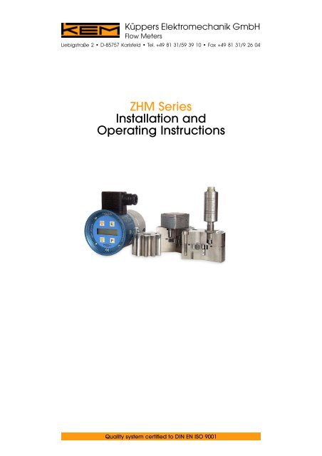
Küppers Elektromechanik GmbHFlow MetersLiebigstraße 2 • D-85757 Karlsfeld • Tel. +49 81 31/59 39 10 • Fax +49 81 31/9 26 04<strong>ZHM</strong> SeriesInstallation andOperating InstructionsQuality system certified to DIN EN ISO 9001
<strong>ZHM</strong> Series Installation and Operating InstructionsPreparationMechanical and electrical installations, start up and maintenance shall only be effected by qualified andauthorised personnel. Please make sure that the measuring range of the <strong>ZHM</strong> cannot be exceeded by morethan 20%. Before installation the pipe system has to be purged. Particles must not get into the gear flowmeter as they could block the gears. This is particularly important with small sizes <strong>ZHM</strong> 01–<strong>ZHM</strong> 02. As aprecaution use filters for the measuring medium:<strong>ZHM</strong> 01–03: 120 micron04–05: 200 micron06–07: 300 micronInstalling the Flow MeterThe gear flow meter should be mounted in flow direction (calibration direction). It can be mounted eitherhorizontally or vertically. The flow direction is indicated by an arrow on the flow meter.The mounting direction is not relevant with reverse flow as in this case the flow meter will have been calibratedfor both flow directions.Our standard gear flow meters are bored to suit Ermeto screwed fittings. No additional sealing is necessaryand never should fibrous sealants such as hemp or teflon strip be used when different connections requireadditional sealing.Sources of InterferenceMagnetic fields and similar sources of interference close to the gear flow meters might affect the pickups.Especially inductive pickups type IF* could react like an antenna. Cables connecting pickup and amplifierand/or evaluation electronics have to be screened, preferably braid-screened.Vibrating pipes can have a resonance effect on the pickup, especially on inductive types. You may preventthis by fitting flexible hose pipes and avoiding a metallic contact between pickup tip and the bottom ofthe pickup bore in the gear flow meter. To do so fit the pickup as follows (not applicable for pickups typeTD*, HD*; VTD* and FOP which are plugged in and fixed by screws):• Screw in the pickup handtight without using force• Slacken pickup by ¼ turn• Tighten the lock nutGas bubbles in the system will falsify measuring results. Gear flow meters are pure volumetric meters.When the meter is installed inside hazardous areas it must only be operated completely filled with fluid.Maintenance• Gear flow meters have to be purged with an adequate solvent if there is no permanent flow or ifthe meters will not be used for a long period of time. Purging is particularly important when fluids arelikely to harden with particles remaining in the flow meter.• The calibration of the gear flow meter should be checked after about 8,000 hours of permanent operation.• The battery of the fibre-optic pickup type FOP 60 is to be exchanged after approx. two years.KEM 3
<strong>ZHM</strong> Series Installation and Operating InstructionsDisassembly and CleaningPlease ensure the line is depressurised, emptied and flushed before disassembly. In case of return shipmentto KEM the <strong>ZHM</strong> must be completely cleaned. This applies in particular for hazardous fluids.All KEM flow meters are of robust design. Therefore a certain amount of force may be requiredduring disassembly. However, never use undue force, if parts do not separate or components cannot beremoved and contact KEM before proceeding.For cleaning purposes gear flow meters may be disassembled by the user as described below (the figures inbrackets refer to the images on page 4). Mark all components with a suitable pen – this will help you tore-assemble them in their original position when re-assembling the meter. O-rings and flat seals must bereplaced by genuine KEM spares.• Remove the pickup (1) from the <strong>ZHM</strong>. Some types of pickups require you tolosen the hidden fixing screws inside the outer through holes to do so.• Slacken the Allen screws (2) and unscrew, but keep two opposed screwsengaged by 1–2 turns. Now remove all others.• Hold onto the upper housing (3) and tap the opposing bolts gently with ahammer/mallet to part the upper and lower housing (4) in parallel directionfrom each other. Do not attempt to use screwdrivers or chisels to split thehousing, as otherwise the shafts, bearings and locating pins may be damaged.• Having separated the housing, remove gears and shafts (5) and clean the parts using a solvent if necessary.Also remove the O-ring (7) and clean the groove except where flat seals (7) are being used with lightweightor cartridge gear flow meters. Remember to replace the seals by genuine KEM spares.Re-Assembly• Upon perfect cleaning of the housing, the gears, shafts and the seal may be inserted. The gears must rotateeasily to provide proper function in future.• When assembling the housing, upper and lower part must be kept parallel,utilising the locating pins (6) in their respective holes. The locating pins mustunder no circumstances be removed or left out. The material codes (see picture)must be placed on top of each other.• Now tighten the Allen bolts observing the torque figures as listed on page 6.4 KEM
<strong>ZHM</strong> Series Installation and Operating Instructions• On completed assembly check the meter to tightness and pressure resistance as per EC directive 97/23/EC.Finally insert the pickup as follows:Types VTE*/P, IF*, VTM, IWA, HE* Types TD*, HD* and FOP 60• Screw in the pickup handtight without using force • Insert pickup in the respective holes• Slacken pickup by ¼ turn• Tighten the fixing screws in the pickup lidTighten the lock nutStandard <strong>ZHM</strong><strong>ZHM</strong> in Lightweight- and Cartridge Designlightweight designcartridge designKEM 5
<strong>ZHM</strong> Series Installation and Operating InstructionsTorque FiguresThe following torque figures are valid for tightening threads according to DIN 13. The figures arebased on a coefficient of friction of µ total = 0.14 (new screw without post treatment, non-lubricated).<strong>ZHM</strong>...CT Cartridge designScrewTorqueM5 Stainless steel M A = 5.9 Nm<strong>ZHM</strong> 01 to 03 round standard shape and lightweight designScrewTorqueM6 12.9 Steel M A = 18 NmM6 Stainless steel M A = 10 NmM10 8.8 Steel M A = 49 Nm<strong>ZHM</strong> 04/1 and 04 round standard shapeScrewTorqueM10 12.9 Steel M A = 84 NmM10 Stainless steel M A = 49 Nm<strong>ZHM</strong> 05 to 06 round standard shapeScrewTorqueM12 12.9 Steel M A = 145 NmM12 Stainless steel M A = 85 Nm<strong>ZHM</strong> 07 round standard shapeScrewTorqueM16 12.9 Steel M A = 365 NmM16 Stainless steel M A = 210 Nm6 KEM
<strong>ZHM</strong> Series Installation and Operating InstructionsPickups and AmplifiersFor safe use of pickups/amplifiers please also refer to the "Safety Instructions for Electrical Devices"Various Pickups are available for gear flow meters. The advantages of the individual types will meet specialrequirements of the measuring task:Application and Features Type Pin/Terminalstandard VTE*/P pin 1 . . . . . . . . . . . . . . . . . . . . . . . . . . . . . . . . . . . . .UB +7 up to 29 VDCfluid temperatures carrier frequency amplifer pin 2 . . . . . . . . . . . . . . . . . . . . . . . . . . . . . . . . . . . . . . . . .signal push pull–20°C...+120°C/150°C with integral pickup pin 3 . . . . . . . . . . . . . . . . . . . . . . . . . . . . . . . . . . . . . . . . . . . . . . . . . . .0 Vpush pull or open collector outputpin 4 . . . . . . . . . . . . . . . . . . . . . . . . . . . . .open collector signal (collector)pin 5 . . . . . . . . . . . . . . . . . . . . . . . . . . . . . .open collector signal (emitter)high resolution, TD* pin 1 . . . . . . . . . . . . . . . . . . . . . . . . . . . . . . . . . . . . .+UB 8 up to 30 VDCreverse flow detection dual carrier-frequency pin 2 . . . . . . . . . . . . . . . . . .out 1 push pull or open collector (fx1 or fx2)ambient temp.: –20°C up to +50°C pickup and amplifier pin 3 . . . . . . . . . . . . . . . . . . . . . . . . . . . . . . . . . . . . . . . . . . . .0 V/groundfluid temp.: up to +80°Cpin 4 . . . . . . . . . . .out 2 push pull or open collector (fx1 or reverse flow)pin 5 . . . . . . . . . . . . . . . . . . . . . . . . . .Com, 0V of open collector outputsLocal display and analogue output VTM pin 1 . . . . . . . . . . . . . . . . . . . . . . . . . . . . . .UB +8 (Ex: ü12) up to 30 VDC4 to 20 mA local display unit pin 2 . . . . . . . . . . . . . . . . . . . . . . . . . . . . . .frequency output, three-wireambient temp.: –40°C...+50°Cpin 3 . . . . . . . . . . . . . . . . . . . . . . . . . . . . . . . . . . . . . . . . . . . .0 V/groundfluid temp.: up to +120/+150°Cpin 4 . . . . . . . . . . . . . . . . . . . . . . . . . . . . . . . . . . . . . . . . . . . . . . . . .–Ioutpin 5 . . . . . . . . . . . . . . . . . . . . . . . . . . . . . . . . . . . . . . . . . . . . . . . . .+Ioutpin 6 . . . . . . . . . . . . . . . . . . . . . . . . . . . . . . . . . . . . . . . . . . . . . . . . .shieldAnalogue output IWA pin 1 . . . . . . . . . . . . . . . . . . . . . . . . . . . . . . . . . . . . . . . . . . . . . . . . . .n.c.4 to 20 mA local converter pin 2 . . . . . . . . . . . . . . . . . . . . . . . . . . . . . . . . . . . . . . . .frequency outputambient temp.: –40°C...+50°Cpin 3 . . . . . . . . . . . . . . . . . . . . . . . . . . . . . . . . . . . . . . . . . . . .0 V/groundfluid temp.: up to +120/+150°Cpin 4 . . . . . . . . . . . . . . . . . . . . . . . . . . . . . . . . . . . . . . . . . . . . . . . . .–Ioutpin 5 . . . . . . . . . . . . . . . . . . . . . . . . . . . . . . . . . . . . . . . . . . . . . . . . .+Iouthigh temperatures IF*HT inductive coil: terminals A,C . . . . . . . . . . . . . . . . . . . . . . . . . . . . . . . . . . . . . . . . . .signalfluid temp.: up to +180°CVIEG inductive amplifier: terminal 1 . . . . . . . . . . . . . . . . . . . . . . . . . . . . . . . . .UB +7 up to 29 VDCfor IF*HTterminal 2 . . . . . . . . . . . . . . . . . . . . . . . . . . . . . . . . . . . . . . . .0 V/groundterminal 3 . . . . . . . . . . . . . . . . . .NPN/PNP output active/passive, 2-wireterminal 4 . . . . . . . . . . . . . . . . . . . . . . . . . . . . . . . . . . . . . . . . . . . .screenterminal 5 . . . . . . . . . . . . . . . . . . . . . . . . . . . . . . . . . . . . . . . .IF*HT coil Aterminal 6 . . . . . . . . . . . . . . . . . . . . . . . . . . . . . . . . . . . . . . . .IF*HT coil Celectro static paint spraying systems FOP fibre optic amplifier: . . . . . . . . . . . . . . . . . . . . . . . . . . . . . . . . . . . . . . .lightwave pulse outputwith 10 kV and more. . . . . . . . . . . . . . . . . . . . . . . . . . . . .to be connected with OPTV receiverresistant to electromagnetic OPTV receiver: terminal 1 . . . . . . . . . . . . . . . . . . . . . . . . . . . . . . . . . . . . . .signal outputinterferenceterminal 2 . . . . . . . . . . . . . . . . . . . . . . . . . . . . . . . . . . . . . . . .0 V/groundFOP: –20°C...+50 °C ambienttemp.terminal 3 . . . . . . . . . . . . . . . . . . . . . . . . . . . . . . . . . . . . . . . . . . . . . .n.c.OPTV: –20°C...+60°Cterminal 4 . . . . . . . . . . . . . . . . . . . . . . . . . . . . . . . . . . . .UB +7...30 V/DCDatasheets with detailed descriptions are available for each pickup.Ex Protection ATEX 100aKEM electronics are available in Ex-protected design, ATEX 100a II 2 G EEx ia IIC T6/T4, and withthe intrinsically safe power supplies type EWS. Gear flow meters can be operated within Ex zone 1.KEM 7
Copyright KEM, subject to change without notice, Zi Rev. 001/09/06Internethttp://www.kem-kueppers.comKüppers Elektromechanik GmbHFlow Meters and Electronics: Design • Manufacture • Distribution


