Manual for Hand Portable Carbon Dioxide Extinguishers. pdf
Manual for Hand Portable Carbon Dioxide Extinguishers. pdf
Manual for Hand Portable Carbon Dioxide Extinguishers. pdf

Create successful ePaper yourself
Turn your PDF publications into a flip-book with our unique Google optimized e-Paper software.
12. Reinstall horn and discharge tube (2 1/2 & 5 lb) or hose and horn assembly (10, 15 & 20 lb) to discharge valve.Check horn strap and clip (10, 15 & 20 lb) <strong>for</strong> damage and proper positioning. Replace, tighten or realign asnecessary.13. Install new tamper seal and record service data on the extinguisher inspection tag.14. Replace the extinguisher on the wall hanger or in the vehicle bracket making sure that it fits the bracket properlyand the bracket is securely attached – replace the bracket if necessary.RECHARGEWARNING: Be<strong>for</strong>e attempting to disassemble, be sure the extinguisher iscompletely empty/depressurized.Use only an approved source of carbon dioxide (see minimumspecifications in NFPA 10 "Inspection, Maintenance & Recharging".Do not use dry ice convertors.Use an approved pump, hose and recharge adapter to insure safeand efficient charge operations.RECHARGING PROCEDURE1. Per<strong>for</strong>m steps 1 through 11 of the "Maintenance-Service Procedure" section.2. Discharge all remaining pressure and contents, making sure that there is no remaining pressure. Retighten valveassembly. A proper valve installation occurs when the minimum tightness is used to make a leak-tight, valve-tocylinderseal. Do not over-tighten valves! (100 ft. lbs. [135.58 Nm] maximum torque). Over-tightening candamage both valves and cylinders and may lead to unsafe situations that can cause property damage, injury and/or loss of life.3. Check the extinguisher nameplate (label) <strong>for</strong> the proper amount of CO2 to be pumped into the extinguisher.4. Install the proper Amerex recharge adapter. Adapter must fit over diffuser tip on 2 1/2, 5 lb Discharge Tube andelbow on 10, 15 & 20 lb without blocking diffuser holes. Do not remove 2 1/2, 5 lb. discharge tube or 10, 15, 20lb. elbow.5. Place extinguisher on an accurate scale and attach carbon dioxide supply line to the recharge adapter.6. Attach a device such as a "Pony Spring Clamp" to hold the extinguisher valve lever in the squeezed position oropen position. Pump the proper amount of CO2 into the extinguisher. When the proper weight is reached, releasethe clamp, shut off the CO2 pump and vent the supply line.7. Remove the CO2 supply line and recharge adapter from the extinguisher valve.8. Check the collar and valve <strong>for</strong> leaks using a leak detection fluid or a solution of soapy water. Remove leak detectionfluid from the valve assembly and wipe exterior of the extinguisher to dry.9. Install ring pin with ring facing the front of the extinguisher.10. Install tamper seal. Record recharge date and attach new recharge tag.11. Install the horn or hose and horn assembly to the extinguisher valve.
TROUBLESHOOTING GUIDEWARNING: Determine the source of a leak be<strong>for</strong>e the extinguisher is depressurized. The extinguishermust be completely depressurized be<strong>for</strong>e any attempt is made to devalve it and correct aleakage problem. To depressurize – hold the extinguisher in a vertical position and slowly squeezethe discharge handle. Thoroughly clean all valve parts after depressurization and valve removal.Amerex CO2 valve bodies and aluminum cylinders are 1-1/8"-12 UNF straight threads. Use a properstraight thread adapter when hydrostatically testing. When reinstalling the valve assembly, the cylindermust be placed in a suitable securing vice. Lubricate o-ring area only. Threads of straightthreadedcylinders require no lubricant <strong>for</strong> proper valve installation. A proper valve installation occurswhen the minimum tightness is used to make a leak-tight, valve-to-cylinder seal. Do not overtightenvalves! (100 ft. lbs. [135.58 Nm] maximum torque). Over-tightening can damage both valvesand cylinders and may lead to unsafe situations that can cause property damage, injury and/or lossof life.PROBLEM1. Leak at collar o-ring2. Leak through valveCORRECTIVE ACTIONRemove valve assembly, clean collar thoroughlyand install new collar o-ring. Lubricate withBluestar V-711 and reinstall valve.Check valve stem seating area <strong>for</strong> scratches or<strong>for</strong>eign matter. Clean seating area with a toothbrush and soft cloth. Install new valve stemassembly.3. Leak at safety relief nutRemove safety nut, disc and gasket assembly.Replace with new Amerex P/N 04000 safety nut,disc and gasket assembly. Tighten assembly to250 in-lbs maximum of torque.4.Leak during dischargeunder discharge leverRemove valve assembly, downtube, spring andvalve stem assembly. Install new valve stemassembly. Check valve seat <strong>for</strong> scratches or<strong>for</strong>eign matter.5.Leak during discharge athose connection elbowTighten hose connection at elbow (10, 15, 20 lb).replace o-ring and/or elbow on 2 1/2 ,5 lb.6. Leak in the cylinderContact Amerex if under warranty – otherwisemark "Rejected" and remove from service orreturn to the owner.
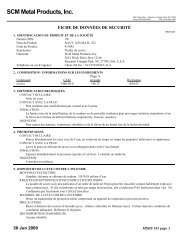
4PARTS LISTFor 2 1/2 –5 lb. <strong>Carbon</strong> <strong>Dioxide</strong><strong>Extinguishers</strong>653Model 322Model 320Model 321Model 322NMModel 320NMModel 321M2116127115A6A89103AItem12PartNo.0309022403224550400022895DescriptionVlv Asy 322/322MNVlv Asy 320/320MN/321Vlv Asy 321M(valve asy does not include elbow/downtube)Safety Disc Gasket & Nut320/320NM/321/322/322NMSafety Disc Gasket & Nut 321M30016016268Ring Pin, Lge Stainless Steel 322/322NMRing pin Sml Stainless Steel320/320NM/321/321M3A 00532 Chain (Nylon) <strong>for</strong> Ring Pin1314154 01387 Lockwire Seal (Yellow)50776223076Lever & Rivet 322/322NMLever & Rivet 320/320NM/321/321M5A 01563 Rivet only <strong>for</strong> Lever60902023077<strong>Hand</strong>le & Rivets 322/322NM<strong>Hand</strong>le & Rivets 320/320NM/321/321M6A 01564 Rivet only <strong>for</strong> <strong>Hand</strong>le (2 reqd)7 05689 O‐ring <strong>for</strong> Elbow8 02735 Elbow with O‐ring91001769225820177222400Discharge Tube 322/322NMDischarge Tube 320/320NM/321/321MHorn 322/322NMHorn 320/320NM/321/321M11 05235 Valve Stem O‐ring12 01539 Valve Stem Assembly13 00501 Spring14 00503 Retainer150053322443Downtube 322/322NMDowntube 320/320NM/321/321M16 01124 Collar O‐ring 1‐1/8"ALL BRACKETS – SEE BRACKET PAGEALL FILL & HYDROTEST ADAPTERS – SEE ADAPTER PAGEALL VALVE ASSEMBLIES INCLUDE VALVE BODY, VALVE STEMASSEMBLY, SPRING, RETAINER, LEVER & HANDLE
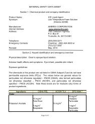
PARTS LISTFor10-15-20 lb. <strong>Carbon</strong> <strong>Dioxide</strong><strong>Extinguishers</strong>4Model 330 Model 331 Model 33221657B785A3ItemPartNo.DescriptionValve Assembly (does not include1 03090elbow or downtube2 04000 Safety Disc, Gasket & Nut3 00160 Ring Pin, Stainless Steel3A 00532 Chain (Nylon) <strong>for</strong> Ring Pin184 01387 Lockwire Seal (Yellow)5 07762 Lever & Rivet5A 01563 Rivet only <strong>for</strong> Lever13147A156A3A106 09020 <strong>Hand</strong>le & Rivets6A 01564 Rivet only <strong>for</strong> <strong>Hand</strong>le (2 req'd)7 02309 Elbow with O-ring & Spacer7A 05689 O-ring <strong>for</strong> Elbow16917117B 02216 Nylon Spacer <strong>for</strong> Elbow8 01776 Hose Assembly–330,331,332901782 Hose & Horn Assembly-33001705 Hose & Horn Assembly-331,33210 00594 U-Pin11 01777 Nozzle1200572 Horn – 33000593 Horn – 331, 33213 05235 Valve Stem O-ring1214 01539 Valve Stem Assembly15 00501 Spring16 00503 Retainer1700564 Downtube – 33000589 Downtube – 331, 33218 01124 Collar O-ring – 1 1/8"192057020571Strap & Clip 330,331Strap & Clip 332ALL BRACKETS – SEE BRACKET PAGEALL FILL & HYDROTEST ADAPTERS – SEE ADAPTER PAGE19ALL VALVE ASSEMBLIES INCLUDE VALVE BODY, VALVE STEMASSEMBLY, SPRING, RETAINER, LEVER & HANDLE