Experiments of Obstacles and Collision Avoidance with a Distributed ...
Experiments of Obstacles and Collision Avoidance with a Distributed ...
Experiments of Obstacles and Collision Avoidance with a Distributed ...

You also want an ePaper? Increase the reach of your titles
YUMPU automatically turns print PDFs into web optimized ePapers that Google loves.
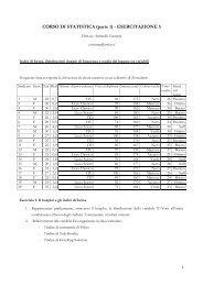
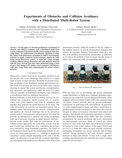
<strong>Experiments</strong> <strong>of</strong> <strong>Obstacles</strong> <strong>and</strong> <strong>Collision</strong> <strong>Avoidance</strong><strong>with</strong> a <strong>Distributed</strong> Multi-Robot SystemFilippo Arrichiello <strong>and</strong> Stefano ChiaveriniDepartment <strong>of</strong> Electrical <strong>and</strong> Information EngineeringUniversity <strong>of</strong> Cassino <strong>and</strong> Southern Lazio03043 Cassino, Italy{f.arrichiello, chiaverini}@unicas.itVaibhav Kumar MehtaL.N. Mittal Insititute <strong>of</strong> Information TechnologyJaipur, Indiavaibhavmehta@ieee.orgAbstract— In this paper we describe preliminary experiments <strong>of</strong>obstacle <strong>and</strong> collision avoidance <strong>with</strong> a distributed multi-robotsystem composed <strong>of</strong> grounded mobile robots equipped <strong>with</strong> laserrange finder. We implemented a localization algorithm to makethe robots avail autonomous navigation in indoor environments,<strong>and</strong> then we apply a behavior based technique, namely the Null-Space based Behavioral control, to make the robots navigateavoiding collision among themselves <strong>and</strong> <strong>with</strong> obstacles detected<strong>with</strong> the laser. Several tests have been performed using a team<strong>of</strong> up to four Khepera III mobile robots equipped <strong>with</strong> HokuyoURG laser range finder <strong>and</strong> communicating via ad-hoc wirelessnetwork.I. INTRODUCTIONMulti-robot systems received an increasing attention in thelast decades due to the advantages they present w.r.t. singlerobot in terms <strong>of</strong> fault tolerance, flexibility in mission execution,possibility to use distributed sensing <strong>and</strong> actuation, etc.The work [12] presents an overview on multi-robot systemsfocusing on aspects like system architecture, communication,task allocation, <strong>and</strong> application; while the work [11] deals<strong>with</strong> the concepts <strong>of</strong> distributed intelligence <strong>and</strong> introducesa classification based on exhibited interactions.Recent researches in this field are mainly focused on distributed<strong>and</strong> cooperative robotic systems [4], i.e. systemswhere each robot interacts only <strong>with</strong> its neighbors <strong>and</strong>,together, they generate the global behavior <strong>of</strong> the team. Thework [8] presents an overview on networked robots, that ismultiple robots that cooperate by network communication,<strong>and</strong> explores the research challenges due to the interactionamong control, communication <strong>and</strong> perception. The book [9]provides an introduction to analysis <strong>and</strong> design <strong>of</strong> dynamicmulti agent networks focusing on graph theoretic methods.Several recent studies deal <strong>with</strong> the development <strong>of</strong> distributedcontrol approaches for multi-robot systems <strong>with</strong> theaim <strong>of</strong> achieving a global task (e.g., controlling the geometricalcentroid) by using distributed controllers. An aspect <strong>of</strong>the mentioned research poses the challenging problem <strong>of</strong> consensusfor multi-agent systems, i.e., reaching an agreementregarding a certain variable depending on the state <strong>of</strong> all theagents. In references [13] <strong>and</strong> [10] the consensus algorithmsare investigated <strong>with</strong> emphasis on robustness, time-delays <strong>and</strong>performance bounds; while the results in [6] are related tothe stability analysis <strong>of</strong> several decentralized strategies thatachieve an emergent behavior. Networked robots give risealso to the problem <strong>of</strong> connectivity maintenance, as addressedin [7], that is the problem <strong>of</strong> how to ensure that the group <strong>of</strong>robots stay connected while accomplishing their task.Fig. 1.Team <strong>of</strong> Khepera III mobile robots.With the final aim <strong>of</strong> developing <strong>and</strong> testing distributedcontrol algorithms, we build up a completely distribute experimentalset-up composed <strong>of</strong> several Khepera III mobile robotsequipped <strong>with</strong> Laser Range Finder (LRF) <strong>and</strong> communicatingvia ad-hoc wireless network. Here we present preliminaryexperiments we performed <strong>with</strong> such platform. In particular,we at first implemented on board each robot a localization algorithmtaken from the literature [14] that allows the robots tonavigate in indoor environment (structured environment <strong>and</strong>corridor). Specifically, the localization algorithm is a featurebasedExtended Kalman Filter (EKF) that uses odometrymeasurement for motion prediction <strong>and</strong> leaser informationfor measurement correction. Then, to control the robotsmotion, we refer to the Null-Space based Behavioral control,developed by some <strong>of</strong> the Authors <strong>of</strong> this paper [2]-[3], <strong>and</strong>we use it to make the robots navigate towards waypoints,exchanging information via ad-hoc network, <strong>and</strong> avoidingcollision among themselves <strong>and</strong> <strong>with</strong> dynamic obstaclesdetected on their path. Results <strong>of</strong> tests <strong>with</strong> a single robotavoiding unpredicted obstacles <strong>and</strong> <strong>with</strong> four robots avoidingcollisions are presented.
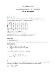
II. EXPERIMENTAL PLATFORMFor the experiments presented here, we used a team <strong>of</strong> fourKhepera III mobile robots, produced by K-Team corporation,that are small size (12cm diameter) differential drive mobilerobots whose base is equipped <strong>with</strong> several proximity sensors(11 infrared sensors TCRT5000 Vishay Telefunken<strong>and</strong>, 5ultrasound sensors 400ST/R100 Midas Components Ltd).The robots have been equipped <strong>with</strong> an extension board,namely the Korebot II, that is an embedded platform basedon the gumstix Verdex PRO <strong>with</strong> a Marvell PXA270 XScaleprocessor @ 600MHz, <strong>with</strong> 128MB RAM <strong>and</strong> 32MB Flashmemories. The Korebot II provides a st<strong>and</strong>ard embeddedLinux operating system (Angstrom distribution, kernel 2.6)<strong>and</strong>, to program it, we made use <strong>of</strong> the Khepera III toolboxdeveloped from the <strong>Distributed</strong> Intelligent Systems <strong>and</strong>Algorithms Laboratory (DISAL) <strong>of</strong> EPFL.To allow robot-robot <strong>and</strong>, eventually, robot-pc communication,the robots have been equipped <strong>with</strong> an IEEE 802.11wireless card. In particular, the robots communicate througha wireless ad-hoc network built <strong>with</strong> the idea to performcompletely distributed experiments. In fact, the final objectiveis to perform experiments in (indoor) large environmentswhere the robots directly communicate only <strong>with</strong> their neighbors(i.e, other robots <strong>with</strong>in the communication range)avoiding fixed access points. Apart from the configuration<strong>of</strong> ad-hoc network parameters, the communication strategyimplemented on board each robot exercises a multi-processarchitecture where each robot is able to broadcast informationusing UDP/IP protocol, <strong>and</strong> store information received fromits neighbors. Eventually, if a robot needs to send specificinformation to a not-directly connected robot, it can usemulti-hop communication. We have tested specific linuxfunctions as ip farwarding <strong>and</strong> olsrd daemon for the same.To improve the robots perception capabilities we equippedthem <strong>with</strong> Hokuyo LRF URG-04LX-UG01. The LRF isconnected to the Korebot II thorough USB but we provide itpower supply from external batteries. The Hokuyo LRF hasadequate performance in terms <strong>of</strong> weight, power consumption,range <strong>and</strong> accuracy, to properly fit <strong>with</strong> Khepera IIIrobots <strong>and</strong> allow them navigating in a indoor environment.III. EXTENDED KALMAN FILTER LOCALIZATIONMobile robot localization (<strong>of</strong>ten called as position estimationor position tracking) is the problem <strong>of</strong> determining the pose<strong>of</strong> a robot relative to a given map <strong>of</strong> the environment, <strong>and</strong> itis one <strong>of</strong> the most basic perceptual problem in robotics. Themaps are usually described in a global coordinate system,thus, localization is the process <strong>of</strong> establishing correspondencebetween the map coordinate system <strong>and</strong> the robotslocal coordinate system. Unfortunately, for indoor or GPSdenied environment, pose usually can not be directly sensed,thus it has to be inferred from data. However, a singlemeasurement is usually not sufficient to properly determinethe pose, <strong>and</strong> the robot has to integrate data over time. Thus,for the localization, the robot needs both a-priory informationabout the environment <strong>and</strong> information from exteroceptivesensors during the navigation.In this paper we refer to the approach presented in [14]-[5] <strong>and</strong> references therein; specifically we implemented afeature based Extended Kalman Filter (EKF) localizationalgorithm where the reference features are represented as linesegments, <strong>and</strong> data association <strong>and</strong> measurement correctionare performed in the Hough domain. Lines, as geometricfeature, provide strong <strong>and</strong> accurate information, but <strong>with</strong>far less numbers than that <strong>of</strong> points. This solution properlyfits <strong>with</strong> our specifications since it works well for indoorenvironment, where the number <strong>of</strong> linear features is high(walls, doors, closets), it does not require high computation(which is <strong>of</strong> primary importance for the robotic platform weare using), it is robust to unpredicted obstacles <strong>and</strong> fit well<strong>with</strong> our obstacle avoidance strategy.In particular, robot localization is performed referring to adiscrete-time formulation <strong>of</strong> the EKF that, as well known,is an approximate estimator for the states <strong>and</strong> parameters <strong>of</strong>nonlinear systems. Here, we assume that the state <strong>and</strong> themeasurement dynamics are respectively governed by:x k+1 = f(x k ,u k )+w k (1)y k = h(x k )+v k (2)where x k is the state (pose <strong>and</strong> orientation),u k is the controlinput, y k is the measurements, w k <strong>and</strong> v k are respectivelyprocess <strong>and</strong> measurement zero mean Gaussian noise <strong>with</strong>R w<strong>and</strong> R v covariance matrixes. Moreover we assume that wecan measure the true initial location x 0 <strong>of</strong> the robot <strong>with</strong>some precision <strong>and</strong> we can use it to initialize the EKF <strong>with</strong>some uncertainty. Then, the EKF implementation follows thetwo-step iterations:A. Prediction <strong>of</strong> state <strong>and</strong> estimation <strong>of</strong> error covarianceThe state prediction is performed on the base <strong>of</strong> the knowledge<strong>of</strong> kinematic model parameters <strong>and</strong> input values. In thespecific case, it is performed using the input values u k =[s l s r ] T (i.e. the left <strong>and</strong> right wheels motion displacements,see fig. 2) <strong>and</strong> the knowledge <strong>of</strong> the odometric [ model ] parameters.The process covariance is R w = l 0 σ20 σr2 wherewe suppose a linear growth <strong>of</strong> the error model covarianceσ l = k l |s l |,σ r = k r |s r |. Thus, the system state is given byposition <strong>and</strong> orientation <strong>of</strong> the robotx k = [x k y k θ k ] T (3)<strong>and</strong> the state prediction update ˆx − k+1 = f(ˆx+ k ,ū k) is givenby:⎡ˆx + ⎤ ⎡⎤(s l,k +s r,k )ˆx − k+1 = k⎣ŷ + 2cos(ˆθ + k⎢+ s r,k−s l,k2b)(sk⎦+ ⎣ l,k +s r,k )2sin(ˆθ + k + s r,k−s l,k⎥2b) ⎦ (4)ˆθ + ks r,k −s l,kb
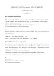
where b is the distance between the wheels. The estimationerror covariance is given byP − k+1= F k P + k FT k +G kR w G T k (5)where F k = ∂f∂x | x=ˆx + ku=ū k<strong>and</strong> G k = ∂f∂u | x=ˆx + ,u=ū k kthat, for the specific case are:⎡⎤⎢1 0 − (sl,k+s r,k )2sin(ˆθ + k + s r,k−s l,k2b)F k =(s⎣0 1 l,k +s r,k )2cos(ˆθ + k + s r,k−s l,k⎥2b) ⎦ (6)0 0 1⎡12G k = ⎣(cos(Θ)+Ssin(Θ)) 12 (cos(Θ)−Ssin(Θ))⎤12 (sin(Θ)−Scos(Θ)) 12 (sin(Θ)+Scos(Θ)) ⎦− 1 bwhere Θ = ˆθ + k + s r,k−s l,k2b<strong>and</strong> S = (s l,k+s r,k )2b.s l,k1b(7)yy [m]1.510.50−0.5−1−1.5−2−1 0 1 2 3x [m]Fig. 3.ρ = xcos(α)+ysin(α)ρ 1α 1Line extraction from LRF scan.l 1l 1(α 1,ρ 1)ρFig. 2.x k+1 ,y k+1 ,θ k+1s r,kx k ,y k ,θ kEKF prediction based on odometric parameters.B. Measurement updates <strong>of</strong> state <strong>and</strong> estimation errorThe measurement update is performed using line informationfrom the LRF. Specifically, to extract line segments from theset <strong>of</strong> points <strong>of</strong> the LRF scan (see fig. 3), we use recursiveline splitting method[1], which is reliable <strong>and</strong> fast. Varioussteps <strong>of</strong> this method are described as follows:1) form a line from start <strong>and</strong> end points <strong>of</strong> the scan;2) find the point <strong>with</strong> the biggest distance to this line;3) if its distance is lower than a certain threshold, a linesegment is found;4) if not, split the point group at this point <strong>and</strong> repeat.After getting the line segments information, they were representedin the Hough Domain. The Hough transform allowsto represent a line represented in a Cartesian coordinateusing two parameters ρ <strong>and</strong> α that respectively represent thedistance <strong>of</strong> the origin from the line <strong>and</strong> the angle <strong>of</strong> thesegments starting from the origin <strong>and</strong> perpendicular to theline (see fig. 4). Thus, for each segments, we store ρ <strong>and</strong> α<strong>and</strong> the coordinates <strong>of</strong> the vertex points.Obtained the list <strong>of</strong> observed features, we have to performthe Data Association, that is, try to associate each observedfeature <strong>with</strong> a corresponding feature <strong>of</strong> the known map. Toallow the correspondence, both maps (a-priori <strong>and</strong> observed)were expressed in the same reference system (the robot localreference system), <strong>and</strong> the comparisons <strong>and</strong> the associationwere made in the Hough domain following the steps:αFig. 4.Transformation <strong>of</strong> line parameters in Hough domain.1) For all the observed l<strong>and</strong>mark (NO), store in a list AHough coordinates <strong>and</strong> segments vertex coordinates;2) For each observed l<strong>and</strong>mark in A find, if there exists,the features <strong>of</strong> the map <strong>with</strong> a certain threshold, i.e.the points in Hough domain <strong>with</strong> distance from thel<strong>and</strong>mark lower than a certain threshold; store them ina list B (see fig. 5);3) Among the different map features in the list B, find thesegment having mid point <strong>with</strong> the minimum distancefrom the observed segment midpoint;4) If the distance between the midpoints is lower thena certain threshold, then associate this feature to theobserved l<strong>and</strong>mark.210−1−2−3−40.5 1 1.5 2 2.5ρxy [m]210−1−2−3 −2 −1 0 1 2 3x [m]Fig. 5. Data association between observed l<strong>and</strong>marks (red) <strong>and</strong> map (blue):correspondence in Hough domain <strong>and</strong> among segments.Indicating the NO observed l<strong>and</strong>marks <strong>with</strong> successful associationprocedure as:y k = [[r 1 ψ 1 ][r 2 ψ 2 ]···[r NO ψ NO ]] Tα
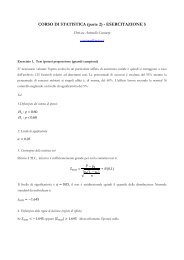
<strong>and</strong> indicating the associated map l<strong>and</strong>marks as:h(ˆx − k+1 ) = [[ρ 1α 1 ][ρ 2 α 2 ]···[ρ NO α NO ]] Tthen the measurement updates <strong>of</strong> state <strong>and</strong> estimation error<strong>of</strong> the EKF has the form:K k+1 = P − k+1 HT k[H k P − k+1 HT k +R v ] −1 (8)ỹ k+1 = y k −h(ˆx − k+1 ) (9)ˆx + k+1 = ˆx − k+1 +K k+1ỹ k+1 (10)P + k+1= (I −K k+1 H k )P − k+1(11)where H k = ∂h ∂x | x=ˆx − = [ H T T1,k NO,k] ...HT <strong>and</strong>k+1[ ]−cos(αi ) −sin(αH i,k =i ) 0.0 0 −1IV. NULL-SPACE BASED BEHAVIORAL CONTROLTo manage robots’ motions we refer to the Null-Space basedBehavioral (NSB) control, that is a behavior based approachdeveloped by some <strong>of</strong> the Authors to control both single<strong>and</strong> multiple robots (see e.g. [2]-[3]). This control approachallows to simultaneously manage multiple tasks arranged inpriority. The basic idea is that the lower priority tasks aresolved in the null-space <strong>of</strong> higher priority ones so that they donot effect them. We report the basic concepts in the following.Let define the position <strong>of</strong> the j th robot as p j = [ ] Tx j y j<strong>and</strong> the generic task variable to be controlled as σ ∈ R mσ = f(p j ) (12)The corresponding differential relationship is:˙σ = ∂f(p j )∂p jv j = J(p j )v j (13)where J ∈ R m×2 is the robot configuration-dependent taskJacobian matrix <strong>and</strong> v j ∈ R 2 is the robot velocity.The motion directives to the robot, i.e. velocity referencecomm<strong>and</strong>, are elaborated as:v d,j = J † (˙σ d +Λ˜σ) (14)where J † = J T (JJ T ) −1 , Λ is a suitable constant positivedefinitematrix <strong>of</strong> gains <strong>and</strong> ˜σ = σ d −σ is the task error.Let us consider the mission for the j th robot composed bytwo elementary tasks. Using the subscript i referring to thei th task quantities for the j th robot, on the analogy <strong>of</strong> theabove equation, the i th task velocity is computed asv i = J † i (˙σ i,d +Λ i˜σ i ) (15)If the subscripti also denotes the degree <strong>of</strong> priority <strong>of</strong> the task<strong>with</strong>, e.g., Task 1 being the highest-priority one, accordingto [3] the final motion comm<strong>and</strong> to the robot is modified into:v f,j = v 1 +(I −J † 1 J 1)v 2 = v 1 +N 1 v 2 (16)whereI is the identity matrix <strong>of</strong> proper dimensions <strong>and</strong>N i isthe null-space projection matrix <strong>of</strong> the i th task. Remarkably,above eq. has a nice geometrical interpretation. Each taskvelocity is computed as if it were acting alone; then, beforeadding its contribution to the vehicle velocity, a lower-prioritytask is projected onto the null space <strong>of</strong> the immediately higherpriority task so as to remove those velocity components thatwould conflict <strong>with</strong> it.For the experiments presented in the next session we considereda multi-robot system where each robot accomplishesan individual task <strong>of</strong> moving toward assigned waypoints (orgoals) avoiding obstacles <strong>and</strong> collision <strong>with</strong> other vehicles.Thus, the mission <strong>of</strong> each robot is decomposed in twoelementary tasks:• Move to Goal. The move-to-goal task function is:σ g = p ∈ R 2 (17)while the desired values is σ g,d = p g where p g are thecoordinates <strong>of</strong> the goal. Since J g = J † g = I ∈ R 2∗2 ,the output velocity is given byv g = Λ g (p g −p) (18)that is a velocity in the goal direction proportional tothe distance from the goal p g .• <strong>Obstacles</strong> <strong>and</strong> collision avoidance. In presence <strong>of</strong> anobstacle in p o in the advancing direction, the aim <strong>of</strong>the task is to keep the robot at a safe distance from it.Therefore the task function isσ o = ||p−p o || ∈ R, (19)<strong>and</strong> σ o,d = S d where S d is the safety distance from theobstacle. Then, it holdsJ o = ˆr T ∈ R 1∗2 (20)where ˆr = p−p o||p−p o ||is the unit vector aligned <strong>with</strong> theobstacle-to-vehicle direction. Therefore, the task outputis a velocity, in the robot-obstacle direction, that keepsthe robot at a safe distance from the obstacle.v o = J † oλ o (S d −||p−p o ||). (21)while the task null-space matrix I − J † oJ o projectsvelocity vectors <strong>of</strong> lower priority task in the directiontangent to a circle centered in p o <strong>and</strong> passing for p.In presence <strong>of</strong> a linear obstacle, the task function isanalogous to the previous case <strong>with</strong> the difference thatp o is the point <strong>of</strong> the segment closest to p.The obstacle-avoidance is usually the highest priority tasksince its achievement is <strong>of</strong> crucial importance to preservethe integrity <strong>of</strong> the vehicle, however it is activated only inspecific conditions, that is when the robot is moving towardthe obstacle <strong>and</strong> when the distance is lower than a certainthreshold (see fig. 6). In this case, the implementation <strong>of</strong>
yyyythe NSB approach makes the robot moving toward the goalsliding around the (point or linear) obstacle keeping a certainsafety distance.GoalN 1v gv gv fv oLinear obstacleFig. 6. Example <strong>of</strong> velocity vector <strong>of</strong> a move to goal function in presence<strong>of</strong> linear obstacles.It is worth noticing that the output <strong>of</strong> the NSB is a linearvelocity comm<strong>and</strong> elaborated considering the robot as amaterial point. To use the NSB to control a non-holonomicvehicle as the Khepera III, the output velocity <strong>of</strong> the NSBis passed to a Low-Level control that properly elaboratesangular <strong>and</strong> advancing velocity <strong>and</strong>, using odometric modelparameters, converts it to left/right wheels velocity comm<strong>and</strong>.In the implementation <strong>of</strong> the algorithms, a saturation isperformed on the resulting velocity in order to feed thesystem <strong>with</strong> limited amplitude signals.V. EXPERIMENTAL RESULTSIn this section we will illustrate two experiments, the firstdone <strong>with</strong> a single robot localizing using the EKF algorithm<strong>and</strong> avoiding obstacles using the NSB control, <strong>and</strong> the secondperformed <strong>with</strong> four robots avoiding avoiding collisions usingboth LRF <strong>and</strong> ad-hoc wireless communication.map <strong>of</strong> the environment available to the robot, while the blacksegments are the segments extracted from the LRF data; itis worth noticing that some <strong>of</strong> that segments are associatedto the map <strong>and</strong> allow the localization, while other segmentsare used for obstacle avoidance. The red triangle representsthe differential drive robot <strong>with</strong> the green vector representingthe v g <strong>and</strong> the blue vector representing the v f velocities forthe robot. The blue/magenta circles represent the referencevalues for the obstacle avoidance task, respectively thresholdfor detection <strong>of</strong> an obstacle <strong>and</strong> safety distance S d . Figure 8shows the sliding behavior <strong>of</strong> the robot around the blackcolored obstacle detected from the LRF. The experiment wasdone <strong>with</strong> the robot’s saturation velocity set to 20 cm/s, Λ gset to a diagonal matrix <strong>with</strong> elements 0.8, <strong>and</strong> λ o set to 1. Acomplete video <strong>of</strong> the experiment that shows the robustness<strong>of</strong> the localization <strong>and</strong> obstacle avoidance algorithms evenin the case <strong>of</strong> a human entering the arena is available athttp://webuser.unicas.it/lai/robotica/video.html54.543.532.521.510.500 0.5 1 1.5 2 2.5 3 3.5 4x54.5454.543.532.521.510.500 0.5 1 1.5 2 2.5 3 3.5 4x54.543.53.5332.52.5221.51.511Fig. 7.Snapshot single robot case.In the first experiment the robot was comm<strong>and</strong>ed to iterativelymove between two waypoints whose coordinate areassigned relatively to the global map <strong>of</strong> the environment. Therobot had two tasks in h<strong>and</strong>: move towards the goal <strong>and</strong> avoiddynamic obstacles eventually detected in the environment.The obstacle avoidance, when active, was the highest prioritytask. Figure 7 shows a single snapshot <strong>of</strong> an iteration wherethe robot detects <strong>and</strong> avoids an obstacle not present inthe environment map. Figures 8 shows several snapshotsillustrating a reconstruction from experimental data <strong>of</strong> therobot behavior. In particular, the blu perimeter represents the0.5Fig. 8.00 0.5 1 1.5 2 2.5 3 3.5 4x0.500 0.5 1 1.5 2 2.5 3 3.5 4xSnapshot single robot case; reconstruction from experimental data.To test the robustness <strong>of</strong> the localization algorithm we alsoperform several tests in noisy indoor environment (a corridor<strong>with</strong> open doors, closets <strong>with</strong> glass wall, people walkingaround); results are not reported here for space limitationbut reconstruction form experimental data is available at theprevious web-page.The second experiment was performed using four Khepera IIIrobots iteratively moving among waypoints. The robots wereinitially displaced in a cross configuration where each robot
yyyyhas to exchange its position <strong>with</strong> his diametral opposite robot.The robots are not coordinate but they exchange their positioninformation using wireless ad-hoc network to facilitate theobstacle avoidance. As for the previous experiment, thesaturation velocity is set to 20 cm/s, Λ g set to 0.8I 2 <strong>and</strong> λ oset to 1. Figure 9 shows a single snapshot <strong>of</strong> the experiment,while fig. 10 shows the reconstruction from the experimentaldata taken from one <strong>of</strong> the robot. As shown in the videoavailable at the previous web-page, the robots also avoidcollisions <strong>with</strong> unpredicted obstacle.four Khepera III mobile robots <strong>with</strong> LRF. We implemented<strong>and</strong> tested a feature-based EKF localization algorithm <strong>and</strong>we used it together <strong>with</strong> a behavior-based motion control,the NSB, to allow the robots navigating in indoor environmentavoiding unpredicted obstacles <strong>and</strong> collisions amongthemselves. Despite in the performed experiments the cooperationamong robots is limited to the position informationexchange for obstacle avoidance, testing the robustness <strong>and</strong>the performance <strong>of</strong> the system represented a preliminaryresult that allows to focus our future work on the development<strong>and</strong> testing <strong>of</strong> distributed coordination control algorithm formulti-robot systems.ACKNOWLEDGMENTSThe Authors would like to thank pr<strong>of</strong>. Gianluca Antonelli for hisvaluable comments <strong>and</strong> suggestions for the realization <strong>of</strong> this work.The research leading to these results has received funding fromthe Italian Government, under Grant FIRB - Futuro in ricerca 2008n. RBFR08QWUV (NECTAR project), <strong>and</strong> under Grant PRIN 2008n. 2008EPKCHX (MEMONET project).54.543.532.521.510.54.53.52.51.50.5Fig. 9.00 0.5 1 1.5 2 2.5 3 3.5 4x54321Fig. 10.00 0.5 1 1.5 2 2.5 3 3.5 4xSnapshot multi-robot case.54.543.532.521.510.54.53.52.51.50.500 0.5 1 1.5 2 2.5 3 3.5 4x5432100 0.5 1 1.5 2 2.5 3 3.5 4xSnapshots multi-robot case; reconstruction from experimental data.VI. CONCLUSIONIn this paper we presents preliminary experiments we performed<strong>with</strong> a distributed multi-robot system composed <strong>of</strong>REFERENCES[1] G.C. Anousaki <strong>and</strong> K.J. Kyriakopoulos. Simultaneous localization <strong>and</strong>map building <strong>of</strong> skid-steered robots. Robotics & Automation Magazine,IEEE, 14(1):79–89, 2007.[2] G. Antonelli, F. Arrichiello, <strong>and</strong> S. Chiaverini. The entrapment/escortingmission: An experimental study using a multirobotsystem. IEEE Robotics <strong>and</strong> Automation Magazine (RAM). SpecialIssues on Design, Control, <strong>and</strong> Applications <strong>of</strong> Real-World Multi-RobotSystems, 15(1):22–29, March 2008.[3] G. Antonelli, F. Arrichiello, <strong>and</strong> S. Chiaverini. The Null-SpacebasedBehavioral control for autonomous robotic systems. Journal<strong>of</strong> Intelligent Service Robotics, 1(1):27–39, Jan. 2008.[4] F. Bullo, J. Cortés, <strong>and</strong> S. Martínez. <strong>Distributed</strong> Control <strong>of</strong> RoboticNetworks. Applied Mathematics Series. Princeton University Press,2009.[5] W. Burgard, D. Fox, <strong>and</strong> S. Thrun. Probabilistic robotics, 2005.[6] A. Jadbabaie, J. Lin, <strong>and</strong> A.S. Morse. Coordination <strong>of</strong> groups <strong>of</strong> mobileautonomous agents using nearest neighbor rules. IEEE Transactionson Automatic Control, 48(6):988–1001, 2003.[7] M. Ji <strong>and</strong> M. Egerstedt. <strong>Distributed</strong> Coordination Control <strong>of</strong> MultiagentSystems While Preserving Connectedness. IEEE Transactions onRobotics, 23(4):693–703, 2007.[8] V. Kumar, D. Rus, <strong>and</strong> S. Sukhatme. Springer H<strong>and</strong>book <strong>of</strong> Robotics,chapter Networked Robots, pages 943–958. B. Siciliano, O. Khatib,(Eds.), Springer-Verlag, Heidelberg, D, 2008.[9] M. Mesbahi <strong>and</strong> M. Egerstedt. Graph theoretic methods in multiagentnetworks. Princeton Univiversity Press, 2010.[10] R. Olfati-Saber, J.A. Fax, <strong>and</strong> R.M. Murray. Consensus <strong>and</strong> cooperationin networked multi-agent systems. Proceedings <strong>of</strong> the IEEE,95(1):215–233, Jan. 2007.[11] L.E. Parker. <strong>Distributed</strong> intelligence: Overview <strong>of</strong> the field <strong>and</strong> itsapplication in multi-robot systems. Journal <strong>of</strong> Physical Agents, 2(1):5,2008.[12] L.E. Parker. Springer H<strong>and</strong>book <strong>of</strong> Robotics, chapter Multiple MobileRobot Systems, pages 921–941. B. Siciliano, O. Khatib, (Eds.),Springer-Verlag, Heidelberg, D, 2008.[13] W. Ren, R.W. Beard, <strong>and</strong> E.M. Atkins. Information consensus inmultivehicle cooperative control. IEEE Control Systems Magazine,27(2):71–82, Apr. 2007.[14] L. Teslić, I. Škrjanc, <strong>and</strong> G. Klančar. Ekf-based localization <strong>of</strong> awheeled mobile robot in structured environments. Journal <strong>of</strong> Intelligent& Robotic Systems, 62(2):187–203, 2011.