Series 810 1/8 DIN Digital Indicator Concise Manual - Pyromation, Inc.
Series 810 1/8 DIN Digital Indicator Concise Manual - Pyromation, Inc.
Series 810 1/8 DIN Digital Indicator Concise Manual - Pyromation, Inc.

Create successful ePaper yourself
Turn your PDF publications into a flip-book with our unique Google optimized e-Paper software.
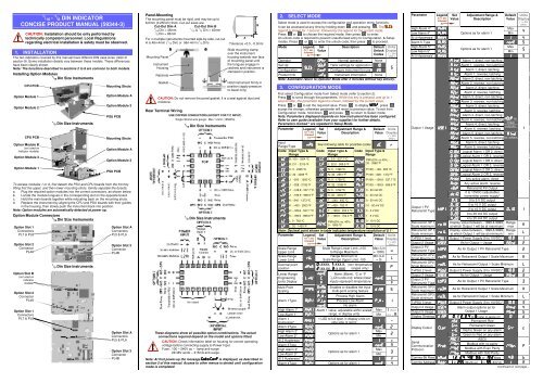
?? ?ParameterComms Write<strong>Digital</strong> InputUsageConfig LockLegendfor 1 secfollowedby4. SETUP MODESetValueAdjustment Range &DescriptionDefaultValueWwWwRead/WriteRead onlyWwWwReset latched relay(s) Initiate Tare (zero display)Reset min/max PV valuesReset Alarm 1 elapsed timeReset Alarm 1 elapsed time & min/max PV values# Config Mode lock code, to )))) UnitsDisplay( 1 /8 DinOnly )Note: Configuration must be completed before adjusting Setup parameters.First select Setup mode from Select mode (refer to section 2). Press to scrollthrough the parameters (while this key is pressed, and for 1 sec after, the parameterlegend is shown, then the current value). Press or to change the value.To exit from Setup mode, hold down and press to return to Select mode.Note: Parameters displayed depends on how instrument has been configured.ParameterInput Filter TimeConstantProcess VariableOffsetRaw PV valueHigh Alarm 1Low Alarm 1Alarm 1HysteresisHigh Alarm 2Low Alarm 2Al 2 HysteresisHigh Alarm 3Low Alarm 3Al 3 HysteresisHigh Alarm 4Low Alarm 4Al 4 HysteresisHigh Alarm 5Low Alarm 5Al 5 HysteresisScalingBreakpoint 1Display Value 1ScalingBreakpoint 2Display Value 2ScalingBreakpoint 3Display Value 3ScalingBreakpoint 4Display Value 4ScalingBreakpoint 5Display Value 5ScalingBreakpoint 6Display Value 6ScalingBreakpoint 7Display Value 7ScalingBreakpoint 8Display Value 8ScalingBreakpoint 9Display Value 9Legendfor 1 secfollowedbySetValueAdjustment Range &DescriptionDefaultValueUnitsDisplay( 1 /8 DinOnly ) OFF or 0.5 to 100.0 secs . ±Span of controller . Linear input value, un-scaled (mA, mV or VDC)blank Alarm 1 value, adjustable within scaled Max (Alm1range, in display units Min only = )1 LSD to full span in display units on safe side of alarm MaxOptions as for alarm 1 Min ! MaxOptions as for alarm 1 Min * MaxOptions as for alarm 1 Min MaxOptions as for alarm 1 Min 5Multi-point scaling breakpoint 1 value,# adjustable from toin % of spanValue to be displayed at multi-point Range scaling breakpoint 1, in display units MaxMulti-point scaling breakpoint 2, adjustable up to# 100% of span. Must be >#valueValue to be displayed at Multi-point scalingbreakpoint 2, in display unitsMulti-point scaling breakpoint 3, adjustable up to## 100% of span. Must be >#valueValue to be displayed at Multi-point scalingbreakpoint 3, in display unitsMulti-point scaling breakpoint 4, adjustable up to# 100% of span. Must be >#valueValue to be displayed at Multi-point scalingbreakpoint 4, in display unitsMulti-point scaling breakpoint 5, adjustable up to# 100% of span. Must be >#valueValue to be displayed at Multi-point scalingbreakpoint 5, in display unitsMulti-point scaling breakpoint 6, adjustable up to#% 100% of span. Must be >#valueValue to be displayed at Multi-point scaling%breakpoint 6, in display units%Multi-point scaling breakpoint 7, adjustable up to#* 100% of span. Must be >#%valueValue to be displayed at Multi-point scaling*breakpoint 7, in display units*Multi-point scaling breakpoint 8, adjustable up to#( 100% of span. Must be >#*valueValue to be displayed at Multi-point scaling(breakpoint 8, in display units(Multi-point scaling breakpoint 9, adjustable up to#) 100% of span. Must be >#(valueValue to be displayed at Multi-point scaling)breakpoint 9, in display units)Tare FeatureEnables or disables the input auto-zero Tare featureSetup Lock Code # to )))) Note: Operator mode screens follow, without exiting from Setup mode.5. MESSAGES & ERROR INDICATIONSThese messages indicate that the instrument may require attention, or there is aproblem with the signal input connection. The message legend is shown for 1second, followed by its value.Caution: Do not continue with the process until the issue is resolved.ParameterInstrumentparameters are indefault conditionsInput Over RangeInput Under RangeLegendfor 1 secfollowedby Input Sensor Break -Value DescriptionUnitsDisplay( 1 /8 DinOnly )Configuration & Setup is required.This screen is seen at first turn on,or if hardware configuration ischanged. Press to enter Configuration Mode, next pressor to enter the unlock code,then press to proceed+,Input signal is > 5% over-rangeInput signal is > 5% under-range+,(>10% under-range for 4 to 20mA,1 to 5V and 2 to 10V ranges)-Break detected in input signalsensor or wiringOption 1 Error.... Option 1 module fault Option 2 Error.. Option 2 module fault Option 3 Error.. Option 3 module fault Option A Error.. Option A module fault Option B Error..Shown if any module is fitted(option B not used on <strong>Indicator</strong>s)Note: +,, +, or - may also be displayed if an incorrect input type isselected.6. OPERATOR MODEThis mode is entered at power on, or accessed from Select mode (see section 2).Note: All Configuration mode and Setup mode parameters must be set asrequired before starting normal operations.Press to scroll through the parameters (while this key is pressed, and for 1 secafter, the parameter legend is shown, followed by the current value).Note: All Operator Mode parameters in Display strategy 6 are read only (see in configuration mode), they can only be adjusted via Setup mode.Legendfor 1 secfollowedby#ValuePVValue*Display Strategy andWhen VisibleAlwaysMax PVMm ValueStrategies , , , , & %Min PVMm ValueStrategies , , , , & % ElapsedTime Alarm 1Value Alarm 2Value Alarm 3Value Alarm 4Value Alarm 5ValueActiveAlarmStatus* Strategies , & %if alarm 1 configured.Format mm.ss to 99.59then mmm.s(10 sec increments)Shows +, if >999.9Strategies , , & %if alarm 1 configuredStrategies , , & %if alarm 2 configuredStrategies , , & %if alarm 3 configuredStrategies , , & %if alarm 4 configuredStrategies , , & %if alarm 5 configuredWhen one or morealarms are activeDescriptionProcess Variable valueRead onlyLatched outputs can be resetMaximum displayed value(inc +, or -)since Mm last reset.To reset, press or for3 seconds,display = &&&& when resetMinimum displayed value(inc +, or -)since Mmlast reset.To reset, press or for3 seconds,display = &&&& when resetAccumulated alarm 1 activetime since last reset.To reset, press or for3 seconds,display = &&&& when resetAlarm 1 value, adjustableexcept in Strategy 6Alarm 2 value, adjustableexcept in Strategy 6Alarm 3 value, adjustableexcept in Strategy 6Alarm 4 value, adjustableexcept in Strategy 6Alarm 5 value, adjustableexcept in Strategy 6L Alarm 4 active Alarm 2 activeAlarm 3 activeAlarm 5 activeLatched outputs can be resetUnitsDisplay( 1 /8 DinOnly )° , ° orblank° , ° orblank° , ° orblank (Alm1only = ) ifalarm 1activeAlarm IndicationThe Active Alarm Status screen indicates any active alarms. In addition, theassociated Alarm LED flashes.For latching alarm outputs, the LED flashes when the alarm condition exists,and goes to ON when the alarm condition is no longer present if the output has notyet been reset.*Resetting Latched Alarm OutputsAny latched outputs can be reset whilst the Process variable or Alarm Statusscreens are displayed, by pressing the or key, via the <strong>Digital</strong> Input (if fitted)or with a communications command via the RS485 module (if fitted).Note: Outputs will only reset if their alarm condition is no longer present.Caution: A reset will affect ALL latched outputs.Additional 1 / 8 Din <strong>Indicator</strong> Units Display and LED’sIn Operator Mode, a Units display shows ° or ° when temperature values areshown. This display is also used in other modes as a confirmation of the parametertype currently shown in the main display. The SET LED indicator is off inOperator Mode, Flashing in Configuration Mode and ON in Set-up mode.MIN and MAX LED’s light when these stored values are shown.Multi-Point ScalingWhen enabled (Mm= ),up to 9 breakpoints can be set tocompensate for non-linear inputsignals.For each breakpoint, the inputscale value (##n) is enteredin % of input span, followed bythe value to be shown (n)in display units.Each breakpoint’s input scalevalue must be higher than theprevious value, but the displayvalues can be higher or lower.Any scale value set to 100%becomes the last in the series.Tare FeatureWhen Tare is enabled (= ), it can be used to set the displayed value tozero automatically, by making the PV Offset parameter equal, but opposite to, thecurrent process variable value. Tare can be initiated via the <strong>Digital</strong> Input (if fitted),with a communications command via the RS485 module (if fitted) or by using thefollowing key press sequence:Press until the process variable is displayed.Hold down and together for three seconds until the display shows /$?Release both keys and press within 3 seconds to confirm the request.The display should read briefly, then begin responding to input signal changes.Note: Tare request is aborted if this sequence is not followed exactly.7. PRODUCT INFORMATION MODEFirst select Product information mode from Select mode (refer to section 2).Press to view each parameter (while this key is pressed, and for 1 sec after, theparameter legend is shown, followed by its value). Hold down and press toreturn to Select mode. Note: These parameters are all read only.ParameterLegendfor 1 secfollowedbyValue DescriptionUnitsDisplay( 1 /8 DinOnly )Input type'Universal inputNo option fitted/ Relay outputOption 1 module SSR drive outputtype fitted Triac output Linear DC voltage / current outputNo option fitted/ Relay outputOption 2 module/Dual Relay (outputs 2 & 4)type fitted SSR drive output Triac output Linear DC voltage / current outputNo option fitted/ Relay outputOption 3 module/Dual Relay (outputs 3 & 5)type fitted SSR drive output Linear DC voltage / current output#24V DC Transmitter power supplyNo option fittedAuxiliary Option A(RS485 communicationsmodule type fitted <strong>Digital</strong> InputFirmware type 01 Value displayed is firmware type number Firmware issue'$$ Value displayed is firmware issue number Product Rev Level . Value displayed is Product Revision Level Manufactured Date MmMonth & year of manufacture. Format mmyy Serial number 1 First four digits of serial numberSerial number 2 Middle four digits of serial numberSerial number 3 Last four digits of serial number #8. SERIAL COMMUNICATIONSDisplayed Value% of SpanRefer to the full user guide (available from your supplier) for details.PV Input Signal9. SPECIFICATIONSUNIVERSAL INPUTThermocoupleCalibration:PT100 Calibration:DC Calibration:Sampling Rate:±0.1% of full range, ±1LSD (±1°C for Thermocouple CJC).BS4937, NBS125 & IEC584.±0.1% of full range, ±1LSD.BS1904 & <strong>DIN</strong>43760 (0.00385Ω/Ω/°C).±0.1% of full range, ±1LSD.4 per second.Impedance: >10MΩ resistive, except DC mA (5Ω) and V (47kΩ ).Sensor BreakDetection:Isolation:DIGITAL INPUTVoltage Input:Volt-free Contacts:Isolation:OUTPUTSRelayContact Type &Rating:Lifetime:Isolation:Dual RelayContact Type &Rating:Lifetime:Isolation:SSR DriverDrive Capability:Isolation:TriacOperating Voltage:Current Rating:Isolation:Thermocouple, RTD, 4 to 20 mA, 2 to 10V and 1 to 5V rangesonly. High alarms activate for thermocouple/RTD sensor break,low alarms activate for mA/V DC sensor break.Isolated from all outputs (except SSR driver).Universal input must not be connected to operator accessiblecircuits if single relay outputs are connected to a hazardousvoltage source. Supplementary insulation or input groundingwould then be required.Reset or Tare occurs on high (2 to 24VDC) to low 500,000 operations at rated voltage/current.Basic Isolation from universal input and SSR outputs.Single pole single throw (SPST), latching or non-latchingaction (selectable); 2A resistive at 120/240VAC.>200,000 operations at rated voltage/current.Reinforced safety isolation from inputs and other outputs.SSR drive voltage >10V into 500Ω min.Not isolated from universal input or other SSR driver outputs.20 to 280Vrms (47 to 63Hz).0.01 to 1A (full cycle rms on-state @ 25°C);derates linearly above 40°C to 0.5A @ 80°C.Reinforced safety isolation from inputs and other outputs.Linear DCAccuracy: ±0.25% (mA @ 250, V @ 2k). Degrades linearly to ±0.5%for increasing burden (to specification limits).Resolution: 8 bits in 250mS (10 bits in 1s typical, >10 bits in >1s typical).Isolation:Transmitter PSUPower Rating:Isolation:SERIAL COMMUNICATIONSPhysical:Protocols:Isolation:Reinforced safety isolation from inputs and other outputs.24V TxPSU Module; Unregulated 20 to 28V DC into 910Ω minLinear output Module; Regulated 0.0 to 10.0V into 500Ω min.Reinforced safety isolation from inputs and other outputs.RS485, at 1200, 2400, 4800, 9600 or 19200 bps.Selectable between Modbus and West ASCII.Reinforced safety isolation from all inputs and outputs.OPERATING CONDITIONS (FOR INDOOR USE)AmbientTemperature:Relative Humidity:Supply Voltage andPower:ENVIRONMENTALStandards:EMI:SafetyConsiderations:0°C to 55°C (Operating), –20°C to 80°C (Storage).20% to 95% non-condensing.100 to 240VAC ±10%, 50/60Hz, 7.5VA(for mains powered versions), or20 to 48VAC 50/60Hz 7.5VA or 22 to 65VDC 5W(for low voltage versions).CE, UL & ULCComplies with EN61326 (Susceptibility & Emissions).Complies with EN61010-1 & UL3121.Pollution Degree 2, Installation Category II.Front Panel Sealing: To IP66 (IP20 behind the panel).PHYSICALFront Bezel Size:1 / 16 Din = 48 x 48mm, 1 / 8 Din = 96 x 48mmDepth Behind Panel: 1 / 16 Din = 110mm, 1 / 8 Din = 100mm.Weight:0.21kg maximum.