View - Institute of Solid State Physics (ISSP), Riga, Latvia
View - Institute of Solid State Physics (ISSP), Riga, Latvia
View - Institute of Solid State Physics (ISSP), Riga, Latvia

Create successful ePaper yourself
Turn your PDF publications into a flip-book with our unique Google optimized e-Paper software.
Home Search Collections Journals About Contact us My IOPscienceAb initio calculations <strong>of</strong> the F centers in MgF 2bulk and on the (001) surfaceThis article has been downloaded from IOPscience. Please scroll down to see the full text article.2012 Phys. Scr. 86 035304(http://iopscience.iop.org/1402-4896/86/3/035304)<strong>View</strong> the table <strong>of</strong> contents for this issue, or go to the journal homepage for moreDownload details:IP Address: 213.175.108.69The article was downloaded on 07/09/2012 at 15:17Please note that terms and conditions apply.
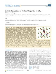
IOP PUBLISHINGPhys. Scr. 86 (2012) 035304 (5pp)PHYSICA SCRIPTAdoi:10.1088/0031-8949/86/03/035304Ab initio calculations <strong>of</strong> the F centers inMgF 2 bulk and on the (001) surfaceA F Fix 1 , F U Abuova 1 , R I Eglitis 2 , E A Kotomin 2 and A T Akilbekov 11 L.N. Gumilyov Eurasian National University, 3 Munaitpasov Street, Astana, Kazakhstan2 <strong>Institute</strong> <strong>of</strong> <strong>Solid</strong> <strong>State</strong> <strong>Physics</strong>, University <strong>of</strong> <strong>Latvia</strong>, 8 Kengaraga Street, <strong>Riga</strong>, <strong>Latvia</strong>E-mail: reglitis@yahoo.comReceived 15 June 2012Accepted for publication 23 August 2012Published 7 September 2012Online at stacks.iop.org/PhysScr/86/035304AbstractWe present and discuss the results <strong>of</strong> atomic and electronic structure calculations <strong>of</strong> the Fcenters in MgF 2 bulk and on the (001) surface. The calculations are based on the B3PWHartree–Fock and density functional theory hybrid exchange-correlation functional. Most <strong>of</strong>the electronic density <strong>of</strong> a missing fluorine ion is localized in the bulk vacancy and a little bitless—in a surface vacancy. It is shown that the electronic F center is a deep donor. The latticedistortion and defect formation energy on the neutral (001) surface and in the bulk are alsocompared.PACS numbers: 31.15.Ar, 61.72.Bb, 61.72.Ji(Some figures may appear in color only in the online journal)1. IntroductionLenses and optical windows made <strong>of</strong> magnesium fluoride(MgF 2 ) are transparent over an extremely wide range <strong>of</strong>photon energies, from vacuum ultraviolet to infrared. It is alsoa radiation-resistant material, the energy required to form astable primary radiation defect known as the F center (fluorinevacancy with trapped electron) between 5 K and roomtemperature is much higher than in other alkali halides [1].These two factors make MgF 2 an important material for spacetelescopes and similar applications. However, it is essentialfor materials scientists to understand at the atomistic levelthe reasons behind MgF 2 ’s high radiation stability. Despiteseveral ab initio calculations <strong>of</strong> basic MgF 2 properties (bothbulk [2, 3] and surfaces [4, 5]), we are not familiar with defectstudies in this material at the ab initio level (unlike otherfluorites—CaF 2 and BaF 2 [6–8]). In this paper, we presentresults <strong>of</strong> the ab initio calculations <strong>of</strong> the F centers in the bulkand on the (001) surface <strong>of</strong> MgF 2 .2. Computational method and surface modelsMgF 2 (rutile) has a tetragonal P4 2 /mnm structure with tw<strong>of</strong>ormula units in the unit cell. As in previous calculations onthe MgF 2 bulk and (001) surface [4, 5], we used here theCRYSTAL computer code [9] using localized, Gaussian-typebasis sets. An advantage <strong>of</strong> this code is the treatment<strong>of</strong> isolated two-dimensional slabs, without an artificialperiodicity in the z direction perpendicular to the surface, ascommonly employed in most previous surface-band structureplane-wave calculations. Our spin-polarized calculations wereperformed using the density functional theory–Hartree–Fock(HF) hybrid exchange-correlation B3PW functional [10]which gives better agreement <strong>of</strong> the calculated andexperimental MgF 2 optical gap than other functionals (9.5 eV(B3PW) versus 19.65 eV (HF), 6.9 eV (generalized gradientapproximation by Perdew, Burke and Ernzerh<strong>of</strong> (GGA-PBE)),compared with the experimental value <strong>of</strong> 12.5 eV—see [4]and figure 1(a)).The reciprocal space integration was performed bysampling the Brillouin zone with 5 × 5 × 5 Pack–Monkhorstmesh [11]. To achieve high accuracy, large enoughtolerances <strong>of</strong> 7, 8, 7, 7 and 14 were chosen forthe Coulomb overlap, Coulomb penetration, exchangeoverlap, first exchange pseudo-overlap and second exchangepseudo-overlap, respectively [8]. In calculations we appliedthe basis set developed by Catti et al [12] for the F atom andby McCarthy and Harrison [13] for the Mg atom. The effectiveatomic charges were calculated using the Mulliken populationanalysis [14].To simulate the F centers, we started with a six-atom(bulk) unit cell with one missing fluorine atom. After thefluorine atom is removed, the atomic configuration <strong>of</strong> the0031-8949/12/035304+05$33.00 Printed in the UK & the USA 1 © 2012 The Royal Swedish Academy <strong>of</strong> Sciences
Phys. Scr. 86 (2012) 035304a)a)A F Fix et alb)c)b)Figure 1. DOS <strong>of</strong> defect-free MgF 2 (a), the F center in bulkcalculated using a 2 × 2 × 2 extended supercell (b) and the surface2 × 2 supercell (c). The peak below −0.3 a.u. is the F(2p) valenceband. The arrow in (a) indicates the position <strong>of</strong> the conduction bandbottom (the experimental value is 12.5 eV). The Fermi energycoincides with the top <strong>of</strong> the defect band.surrounding atoms is reoptimized via a search <strong>of</strong> the totalenergy minimum as a function <strong>of</strong> the atomic displacementsfrom the regular lattice sites. This corresponds to a highdefect concentration <strong>of</strong> 25%. Then we repeated thesecalculations for a 2 × 2 × 2 times expanded supercell (3%defect concentration) in the bulk and a 2 × 2 × 1 supercellfor the surface (a slab model consisting <strong>of</strong> nine neutralMgF 2 crystalline layers—12.5% <strong>of</strong> surface defects). As aresult <strong>of</strong> these calculations, we obtained the relaxed latticegeometry, effective atomic charges and bond populations, theband structure, density <strong>of</strong> states (DOS) and defect formationenergies.In order to get an accurate description <strong>of</strong> the F center,an extra basis set has been centered in the fluorine vacancy,corresponding to the ghost atom. For the ghost atom, we usedthe same basis set as that used for the F − ions <strong>of</strong> the bulkMgF 2 .The defect formation energy was calculated as usual:E form (F) = E(Fluorine) + E(F)-E(perfect), (1)where E(Fluorine) is the energy for the isolated fluorineatom, E(F) and E(perfect) the energies <strong>of</strong> the defective crystalcontaining the F center and the perfect crystal, respectively.c)Figure 2. (a) A schematic view <strong>of</strong> the MgF 2 lattice with shaded(100) and (001) planes, (b) F center nearest-neighbor geometry(unit cell extension 2 × 2 × 2) projected onto the (100) plane and (c)onto the (001) plane. Full circles are Mg ions, empty circles F ions.3. Main results3.1. Bulk defectThe fluorine vacancy formation energy, calculated for thesmall supercell <strong>of</strong> six atoms is 9 eV, which is a typical value2
Phys. Scr. 86 (2012) 035304A F Fix et alTable 1. Displacements <strong>of</strong> the defect nearest neighbors (see atomic labeling in figure 2(b)), values are both in Å and in fractions (%) withrespect to the tetragonal lattice parameters.Neighbors <strong>of</strong> Fcenter (vacancy)Atomic displacementsx(Å) x/a y(Å) y/b z(Å) z/cMg (1) 0.0065 0.14 0.0065 0.14 0 0Mg (2) −0.0094 −0.20 −0.0094 −0.20 0.0029 0.10F (3) 0.0034 0.07 0.0064 0.14 0 0F (4) −0.0057 −0.12 −0.0057 −0.12 0 0F (5) 0.0003 0.01 0.009 0.20 0.0027 0.07F (6) −0.0118 −0.25 −0.0027 −0.06 0.0024 0.08a) Difference electron density b) Total electron densityFigure 3. The difference (a) and total electron density (b) distributions around the bulk F center (marked by a black square in (b)). Theeffect <strong>of</strong> a small electron density delocalization from a vacancy over nearest neighbors is seen in (a).Table 2. The effective charges Q(e) <strong>of</strong> the F center and nearestneighbors in the MgF 2 bulk calculated for a supercell containing 48atoms and their deviations from a perfect crystal. Atomic labels asin table 3.Atom Q(e) Q(e)Mg (1) 1.75 0.006Mg (2) 1.745 0.011F (3) −0.88 0.002F (4) −0.883 0.005F (5) −0.883 0.005F (6) −0.887 0.009for the F centers in alkali halides and ionic solids. An analysis<strong>of</strong> the effective charges <strong>of</strong> atoms surrounding the F centershows that the electron associated with the removed fluorineatom is well localized inside the fluorine vacancy (−0.769e).Note that the effective charges in the defect-free crystal are1.755e (Mg) and −0.878e (F) [4]. The relevant Mg–F bondpopulation in a perfect crystal is 42 me (milli electrons), quitelow, which is typical for ionic solids. That is, most <strong>of</strong> theelectron density <strong>of</strong> a missing fluorine ion is localized in thevacancy even at such high defect concentrations, only ≈ 10%is delocalized over the nearest ions.An incorporation <strong>of</strong> a vacancy produces anisotropy in thebond populations: some Mg–F bonds became less populated(14 me) than those in the perfect crystal whereas others showlarger populations (60 me). These is also a very weak overlap<strong>of</strong> the electronic density in a vacancy and one <strong>of</strong> nearest Mgions (14 me).The calculated DOS shows that due to the small size <strong>of</strong>the unit cell and thus a short distance between periodicallyrepeated defects, they strongly interact which results in a verybroad defect band (≈ 3 eV) which overlaps with the bottom<strong>of</strong> the conduction band.Next, calculations were performed for a more realisticdefect concentration <strong>of</strong> 3% (one F ion removed from a48 atom supercell with 32 F ions) shown schematically infigure 2.The DOS (figure 1(b)) clearly indicates that at thisconcentration periodic defects interact only moderately, whichresult in a narrow F center band (width ≈ 0.5 eV). Thedefect band lies deep below the conduction band bottom.Its formation energy is 7.8 eV, smaller than for the highdefect concentration discussed above, and surprisingly closeto that in fluorite crystals—CaF 2 and BaF 2 (7.9 and 7.8 eV,respectively [6, 7]).Notice that we calculated the formation energies <strong>of</strong> asingle F center. This energy typically is much smaller than theirradiation energy necessary to produce one stable F center[1], since most <strong>of</strong> the F centers recombine in the secondaryreactions, e.g. with mobile complementary defects—Hcenters (interstitial F ions). For instance, the efficiency <strong>of</strong> theF center accumulation in MgF 2 is by an order <strong>of</strong> magnitudesmaller than in LiF crystals [15]. To understand this effect,after the present calculations <strong>of</strong> the defect static properties,defect mobilities and aggregation should be simulated.3
Phys. Scr. 86 (2012) 035304Table 3. The same as table 1 for the surface F center (see atomic labeling in figure 4).Neighbors <strong>of</strong>F centerAtomic displacementsx(Å) x/a y(Å) y/b z(Å) z/cMg (1) 0.0581 1.25 −0.0581 −1.25 −0.1838 −5.86Mg (2) 0.0046 0.10 −0.0046 −0.10 0.0267 0.85F (3) 0.0861 1.84 −0.0858 −1.84 0.0327 1.04F (4) 0.0399 0.86 −0.1209 −2.60 0.0327 1.04F (5) −0.0399 −0.86 −0.0399 −0.86 0.0057 0.18F (6) −0.0002 −0.01 −0.0466 −1.00 −0.0664 −2.12F (7) −0.0357 −0.77 −0.0143 −0.31 −0.048 −1.53F (8) 0.0466 1.00 0.0002 0.01 −0.0664 −2.12F (9) 0.0143 0.31 0.0357 0.77 −0.048 −1.53A F Fix et alTable 4. The effective charges Q(e) <strong>of</strong> atoms surrounding the Fcenter on the (001) surface. Atomic symbols as in figure 4.Atom Q(e) Q(e)Mg (1) 1.668 0.088Mg (2) 1.741 0.015F (3) −0.874 −0.004F (4) −0.874 −0.004F (5) −0.880 0.002F (6) −0.911 0.033F (7) −0.897 0.019F (8) −0.911 0.033F (9) −0.897 0.019The defect formation energy could be also determinedwith respect to the thermodynamic reference energy—the Fatom in a free F 2 molecule. For this estimate half the bindingenergy <strong>of</strong> the F 2 molecule (1.6 eV) should be subtracted fromthe energy calculated with respect to a free atom, which gives7.0 eV.Table 1 presents the calculated lattice relaxation aroundthe defect, in absolute values and as fractions <strong>of</strong> the tetragonallattice parameters (the optimized values in a perfect MgF 2are: a = b = 4.654 Å, c = 3.139 Å [4] which is close toexperimental data).As one can see here, ionic relaxation around the defect issmall, displacements are less than 2%. This is accompaniedby small changes in the relevant atomic charges (table 2),whereas the charge <strong>of</strong> a vacancy itself is increased to 0.1e,due to the density delocalization over the nearest ions. This isconfirmed by the electron density maps in figure 3.3.2. Surface F centersFor a comparison, we calculated the F center on theneutral MgF 2 (001) surface. The defect formation energy is8.4 eV, larger than in the bulk. Such effects were observedalso in other materials, e.g. on the LaO (100) surface<strong>of</strong> LaMnO 3 [16]. The calculated atomic displacements aresummarized in table 3, with a schematic configuration shownin figure 4. First <strong>of</strong> all, ions at the surface show largevertical displacements, up to ≈ 6% <strong>of</strong> the lattice constant.Second, surface cations are displaced inwards whereas anionsare displaced <strong>of</strong>f the surface, qualitatively similar to thedefect-free surface [6]. This leads to the surface rumpling.Relaxation in the surface plane along the x, y axes is also largerthan in the bulk, up to ≈ 2%. This results from additionaldelocalization <strong>of</strong> the electronic density from the surfacea)b)Figure 4. The same as figure 2, for the surface F center.vacancy which contains only −0.622e, i.e. increased by 0.12ecompared with the bulk defect. This could be one <strong>of</strong> reasonsfor the increased defect formation energy. The width <strong>of</strong> thedefect band in the DOS (figure 1(c)) is 0.4 eV, slightly smallerthan for the bulk F center whereas the electronic density mapremains qualitatively similar to that in the bulk (table 4).4. ConclusionsOur ab initio calculations show that use <strong>of</strong> 2 × 2 × 2 supercell(48 atoms) with 3% defect concentration gives reasonableresults and could be employed in further MgF 2 studies.The relevant F center formation energy is similar to that4
Phys. Scr. 86 (2012) 035304calculated for CaF 2 with a fluorite structure. Most <strong>of</strong> theelectronic density <strong>of</strong> a missing fluorine ion is localizedin the bulk vacancy and, a little bit less, in a surfacevacancy. The electronic F center is a deep donor. The defectformation energy on the neutral (001) surface is larger thanin the bulk, thus, this surface is expected to have a lowdefect concentration. This is important for the material spaceapplications in a radiation environment. In a forthcomingstudy we will discuss F center diffusion which is expected todiffer considerably in rutile (MgF 2 ) and fluorite (CaF 2 , BaF 2 )crystals.AcknowledgmentsMany thanks due to V Lisitsyn and V Korepanov forstimulating discussions. RE was supported by ESF grant no.2009/0202/1DP/1.1.1.2.0/VIAA/141.References[1] Blunt R F and Cohen M I 1967 Phys. Rev. 153 1031Buckton M R and Pooley D 1972 J. Phys. C: <strong>Solid</strong> <strong>State</strong> Phys.5 1553A F Fix et al[2] Catti M, Pavese A, Dovesi R, Roetti C and Causa M 1991Phys. Rev. B 44 3509[3] Babu K R, Lingam Ch B, Auluck S, Tewari S P andVaitheeswaran G 2011 J. <strong>Solid</strong> <strong>State</strong> Chem. 184 343[4] Vassilyeva A F, Eglitis R I, Kotomin E A and Dauletbekova AK 2010 Physica B 405 2125[5] Vassilyeva A F, Eglitis R I, Kotomin E A and Dauletbekova AK 2011 Cent. Eur. J. Phys. 9 515[6] Shi H, Eglitis R I and Borstel G 2005 Phys. Rev. B 72 045109[7] Shi H, Eglitis R I and Borstel G 2006 J. Phys.: Condens.Matter 18 8367[8] Shi H, Jia R and Eglitis R I 2011 <strong>Solid</strong> <strong>State</strong> Ion. 187 1[9] Saunders V R, Dovesi R, Roetti C, Causa M, Harrison N M,Orlando R and Zicovich-Wilson C M 2006 CRYSTAL UserManual (Torino, Italy: University <strong>of</strong> Torino)[10] Becke A D 1993 J. Chem. Phys. 98 5648[11] Monkhorst H J and Pack J D 1976 Phys. Rev. B 13 5188[12] Catti M, Dovesi R, Pavese A and Saunders V R 1991 J. Phys.:Condens. Matter 3 4151[13] McCarthy M I and Harrison N M 1994 Phys. Rev. B49 8574[14] Catlow C R A and Stoneham A M 1983 J. Phys. C: <strong>Solid</strong> <strong>State</strong>Phys. 16 4321[15] Lisitsyna L A, Lisitsyn V M, Korepanov V I and Grechkina TV 2004 Opt. Spectrosc. 96 230[16] Mastrikov Yu, Merkle R, Heifets E, Kotomin E A and Maier J2010 J. Phys. Chem. C 114 30175