Implementation of a 3D Graphics Rasterizer - Research Inventy
Implementation of a 3D Graphics Rasterizer - Research Inventy
Implementation of a 3D Graphics Rasterizer - Research Inventy

Create successful ePaper yourself
Turn your PDF publications into a flip-book with our unique Google optimized e-Paper software.
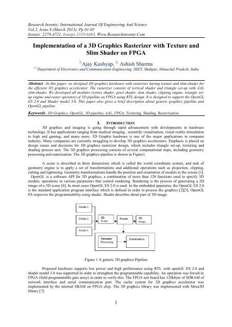
<strong>Research</strong> <strong>Inventy</strong>: International Journal Of Engineering And ScienceVol.2, Issue 8 (March 2013), Pp 01-05Issn(e): 2278-4721, Issn(p):2319-6483, Www.<strong>Research</strong>inventy.Com<strong>Implementation</strong> <strong>of</strong> a <strong>3D</strong> <strong>Graphics</strong> <strong>Rasterizer</strong> with Texture andSlim Shader on FPGA1, Ajay Kashyap, 2, Ashish Sharma1,2, Department <strong>of</strong> Electronics and Communication Engineering, HIET, Shahpur, Himachal Pradesh, IndiaAbstract –In this paper, we designed <strong>3D</strong> graphics hardware with rasterizer having texture and slim-shader forthe efficient <strong>3D</strong> graphics accelerator. The rasterizer consists <strong>of</strong> vertical shader and triangle set-up with AALslim-shader. We developed all modules (vertex shader, pixel shader, slim shader, clipping engine, triangle setupengine and raster operator) <strong>of</strong> <strong>3D</strong> pipeline on FPGA using RTL design. It is designed to support the OpenGLES 2.0 and Shader model 3.0. This paper also gives a brief description about generic graphics pipeline andOpenGL pipeline.Keywords- <strong>3D</strong> <strong>Graphics</strong>, OpenGL, <strong>3D</strong> pipeline, AAL, FPGA, Texturing, Shading, Rasterization.I. INTRODUCTION<strong>3D</strong> graphics and imaging is going through rapid advancement with developments in hardwaretechnology. It has applications ranging from medical imaging , scientific visualisation, visual reality stimulationto high end gaming, and many more. <strong>3D</strong> Graphic hardware is one <strong>of</strong> the major applications in computerindustry. Many companies are currently struggling to develop <strong>3D</strong> graphics accelerators. Emphasis is placed ondesign issues and decisions for <strong>3D</strong> graphics rasterizer design, which includes triangle set-up, texturing andshading process unit. The <strong>3D</strong> graphics processing consists <strong>of</strong> several computational steps, including geometryprocessing and rasterization. The <strong>3D</strong> graphics pipeline is shown in Figure1.A scene is described in three dimensions which is called the world coordinate system, and task <strong>of</strong>geometry engine is to apply a set <strong>of</strong> transformations and additional operations such as projection, clipping,cutting and lightening. Geometry transformations handle the position and orientation <strong>of</strong> models in the screen [1].OpenGL is a s<strong>of</strong>tware API for <strong>3D</strong> graphics, a combination <strong>of</strong> more than 120 functions used to specify <strong>3D</strong>models, operations in various parameters that control rendering. Rendering is the process <strong>of</strong> generating a 2Dimage <strong>of</strong> a <strong>3D</strong> scene [4]. In most cases OpenGL ES 2.0 is used. In the embedded apparatus, the OpenGL ES 2.0is the standard application program interface which is defined in order to process the graphics [2][3]. OpenGLES improves the programmability using shader. Shader describes detail part <strong>of</strong> <strong>3D</strong> image.Figure 1 A generic <strong>3D</strong> graphics PipelineProposed hardware supports low power and high performance using RTL with openGL ES 2.0 andshader model 3.0 was supported in order to strengthen the programmable capability. An operation was forced inFPGA (field programmable gate array) in order to verify this. The FPGA test board has 128kbyte <strong>of</strong> SDRAM <strong>of</strong>network interface and serial communication port. The cache system for <strong>3D</strong> graphics accelerator wasimplemented by the internal SRAM on FPGA chip. The <strong>3D</strong> graphics library was implemented with Mesa<strong>3D</strong>library [7].1
<strong>Implementation</strong> Of A <strong>3D</strong> <strong>Graphics</strong> <strong>Rasterizer</strong>…II. RASTERIZATIONIn rasterization vertices associated with each primitive has 2D screen coordinates, primitives areessentially triangles. In addition to 2D screen coordinated each vertex has color and texture coordinates with areused to color and texture the triangle. From this point on rasterization gets complex with enormous amount <strong>of</strong>data sets and computations [8].Rasterization is a process <strong>of</strong> taking a 2D image and converting it into pixels ordots for output on a video display. Task <strong>of</strong> rasterization is to identify all pixels that are covered by theprimitive (triangle in our case), assign color and additional attributes to each such pixel [5]. Scan converting atriangle generates a set <strong>of</strong> pixels which fall inside triangle which hereafter referred as fragments. Each fragmentgets its own x, y screen coordinates, color and texture coordinates computed by interpolating color, texturevalues across triangle edge and across scan lines.Figure 2 Rasterization pipelineA. Scan2D screen can be thought as rectangular grid <strong>of</strong> pixel having values x and y [9][10]. The x valueincreases along horizontal and y along vertical respectively. Each scan line is represented by y. Rasterizationunit gets 2D screen co-ordinates <strong>of</strong> vertices associated with each primitive. Scan conversion starts by sorting thevertex in decreasing order <strong>of</strong> y, which starts with top most scan line transverses down to bottom most scan linethat intersects the primitive.XFigure3. Triangle covering pixel centres.Scanning generates fragments for each pixel that falls inside the primitive (triangle) with respective x, yscreen co-ordinates [6]. Scan conversion also assigns texture co-ordinates; color and death values to eachfragment generated depending upon the shading and texture modes. Task <strong>of</strong> triangle setup, edge-walk and spaninterpolation is to generate fragments that fall inside the given triangle at the same time assign, color, depth andtexture co-ordinates to each such fragment.. Task <strong>of</strong> triangle setup, edge-walk and span interpolation is togenerate fragments that fall inside the given triangle at the same time assign, color, depth and texture coordinatesto each such fragment.B. TexturingTexturing is a process <strong>of</strong> printing an image on to a rendered surface. It is one <strong>of</strong> the most usefultechnique used in modern graphics machines to render realistic images. Texture mapping proceeds through threephases to assign color to each pixel that falls inside the polygon (triangle).Compute texture co-ordinates at each pixel inside the primitive.Read texels from texture images.Filter texels.Modify the fragment color.2
<strong>Implementation</strong> Of A <strong>3D</strong> <strong>Graphics</strong> <strong>Rasterizer</strong>…Textures are simple rectangular arrays <strong>of</strong> data for example textures can be represented as rectangulargrid <strong>of</strong> texels each <strong>of</strong> which can be addressed with(u, v) texture co-ordinates just as screen pixels can beaddressed with x, y screen co-ordinates. Texels contain color information such as RGB and in some case analphabet value is also present. Each fragment gets its texture co-ordinates and the location <strong>of</strong> the base textureimage in the texture memory. The idea <strong>of</strong> texture mapping is to read respective texel RGBA values frommemory filter according to filtering mode to remove anti-aliasing artifects and distortion. There are three types<strong>of</strong> filtering modes point sample, bilinear, and trilinear.Several buffers are needed for <strong>3D</strong> graphics processing, which are the frame buffers for storing colorvalues <strong>of</strong> each pixel, the alpha buffer for storing transparency value <strong>of</strong> each pixel, and the depth (z) buffer forstoring depth value <strong>of</strong> each pixel in local memory (SDRAM). All <strong>of</strong> these buffers have 16-bit size per one pixelon this platform, in addition after a screen is rendered, every buffer could be cleared before the next scenegenerates. Proposed <strong>3D</strong> graphics hardware operated with 35MHz in the increased vertex5 and it is able to renderthe 70,000 triangles at 30 frames/second.III. PROPOSED RASTERIZATIONA triangle vertex data structure in addition to screen co-ordinates x and y will also contain RGBA colorvalues which are used to assign color to individual fragments during scan conversion. Presently shadings are <strong>of</strong>two types flat and gourmand shading. Flat shading assigns single color to a primitive depending on surfacenormal as a result, all the pixels that fall inside are assigned the same color. Flat shading is really very simple toimplement. To fill a triangle with flat shading we set same color to each pixel inside the triangle whereas ingoround shading each vertex gets a different color. The proposed slim shader performs the main renderingoperation such as texturing, shading, blending and depth comparison. Memory programmer (MP) enables thespecial effect such as anti-aliasing, motion-blurr and fog to be programmable. Integrated DRAM with partialboard line scheme provides sufficient bandwidth and capacity required for <strong>3D</strong> rendering operation. In slimshader vertical strip assignment is done as shown in figure4. Triangle is divided into two alternative strips <strong>of</strong> Aand B. We have two pixel processors PP0 and PP1. Here horizontal order rasterization is done.Figure4. Slim shader triangle setupA triangle setup engine (TSE), which contains single cycle parallel divider distributes triangle to twopixel processors (PP), it enhances the overall performance <strong>of</strong> <strong>3D</strong> pipeline by accelerating setup operation. Slimshader prevents the unnecessary shading and texturing by gating <strong>of</strong> the clock. For real time special effects, MPpost-processes where the rendered pixels <strong>of</strong> the previous frame transferring them to the display control. Texturememory is integrated with two texture engines (TE). Per pixel dividers are implemented in each TE to supportperspective correct addressing which can remove the artifects in large triangles. Rasterization engine with slimshader is shown in the figure5.Figure5. Slim shader3
<strong>Implementation</strong> Of A <strong>3D</strong> <strong>Graphics</strong> <strong>Rasterizer</strong>…Here since TEs perform the bilinear MIPMAP filtering to draw more realistic images, 8 texel requestsare generated at every cycle fetching 8 texels directly from 8 TMs may consume large amount <strong>of</strong> power due toconcurrent data transition in many capacitive I/Os and the activation power <strong>of</strong> TMs themselves. Therefore, thenumber <strong>of</strong> memory requests is reduced by adopting address alignment logic. Since the two PPs process adjacentpixels, the nature <strong>of</strong> MIPMAP filtering allows special Aligner to find and remove the overlapped texels. ThenAligner compares the current texture addresses with previous ones and leaves only the different addresses. SinceAAL reduces the average number <strong>of</strong> requests to less than 2.5, texels can be fetched from only TMs at everycycle. AAL saves power by reducing the number <strong>of</strong> activated TMs while doubling the performance comparedwith single TE architecture. AAL reduces 68% <strong>of</strong> energy required as compared to single TE architecture.IV. VERIFICATIONA <strong>3D</strong> graphics verification system is comprised <strong>of</strong> the platform including the test bench for simulationand ARM processor subsystem and <strong>3D</strong> graphics IP module targeted in FPGA. The platform performing the hostcontroller roll <strong>of</strong>f <strong>3D</strong> graphics module is used in a simulation and does a role <strong>of</strong> a platform. A <strong>3D</strong> graphicsaccelerator usually produces a very large amount <strong>of</strong> pixel data. It is almost impossible to compare the simulationdata and C program data by hand. Automated tools are needed for the simulation data comparison, datapresentation and data acquiring in <strong>3D</strong> graphics pipeline. The <strong>3D</strong> graphics accelerator verification environment iscomposed <strong>of</strong> a C program language model <strong>of</strong> the <strong>3D</strong> graphics pipelining.. An FPGA target board is used toverify the functionality <strong>of</strong> the implementation. The target board is used to verify the entire SoC architecture,which consists <strong>of</strong> ARM processor, an FPGA chip and peripheral blocks. Figure 6 shows the estimatedperformance <strong>of</strong> the embedded <strong>3D</strong> graphics accelerator.Figure 6. Rsterizer PerformanceV. CONCLUSIONThe <strong>3D</strong> graphics rasterizer architecture is designed and verified with an FPGA board. The proposed <strong>3D</strong>graphics rasterizer has a triangle setup, edge-walk, slim shader, AAL and span processing unit. It supports slimshading with 16-bit color and 16-bit depth values. Scan conversion algorithm are used in the design <strong>of</strong> the <strong>3D</strong>graphics rasterizer. Simulation results were visualized and intermediate date about the graphic pipeline wereverified by comparing the results <strong>of</strong> a C model. This paper suggests effective <strong>3D</strong> graphic hardware. It isdesigned to support the openGL ES 2.0 and shader model 3.0. We design <strong>3D</strong> graphic accelerator and verify onFPGA platform.REFERENCES[1] Foley, Van Dam; “Computer <strong>Graphics</strong> Principles and Practice”, Second Edition, 2003.[2] OpenGL ES, http://www.khronos.org/opengles.[3] Richard S, “OpenGL Super bible”, Third Edition, 2004.[4] Bo Han and Bingfeng Zhou,”Efficint Video Decoding on GPUs by Point Based Rendering”, <strong>Graphics</strong> Hardware, 2006.[5] Anders Kugler,” The Setup for Triangle Rasterization”, 11 th Euro graphics workshop on Computer <strong>Graphics</strong>Hardware, August 26- 27, Poitiers Ffrance, 1996.[6] “An Effective Pixel Rasterization Pipeline Architecture for <strong>3D</strong> Rendering Processors”, IEEE Transactions onComputers, Vol.52., No-11, PP1501-1508, November 2003.[7] Mesa <strong>3D</strong> <strong>Graphics</strong> Library, http://www.mesa3d.com.[8] Z. S. Hakura and A. Guptsa,” The Design and Analysis <strong>of</strong> a Cache Architecture for Texture Mapping”, Proceeding <strong>of</strong> the 24 thInternational Symposium on Computer Architecture, PP 108-120, June 1997.[9] Hyun Jae Woo,” A Design <strong>of</strong> an Effective Control and Execution Method For Geometrical Engines andRasterization within Embedded <strong>3D</strong> <strong>Graphics</strong> Accelerator”, Yonsei Univ. Phd Thesis, 2003.12[10] Tomas, Eric,” Rel-Time Rendering”, Second Edition, 20024
<strong>Implementation</strong> Of A <strong>3D</strong> <strong>Graphics</strong> <strong>Rasterizer</strong>…AUTHORS PROFILEMr. Ajay Kashyap received his M. Tech degree from GBTU, Lukhnow,Uttar Pradesh,India and his BE from NMU, jalgaon,India.Presently he is working as HOD inDepartment <strong>of</strong> ECE in Himachal Institute <strong>of</strong> Engineering and Technology. He had wideexperience In Teaching and carried out many project at Graduate And post graduatelevel for his students.hereMr. Ashish Sharma is Pursuing his MTech degree from BUEST, Baddi, HimachalPradesh. and he is BE in E&TC from NMU, Jalgaon (M.S.), India. He is presentlyWorking with Himachal Institute <strong>of</strong> Engineering and Techmology, Kangra, India. Hehas enough Experience in his field and he is very young and dynamic member <strong>of</strong> hisinstitution.5