

V248 Series 3-Way Pressure-Actuated Water-Regulating Valves for ...
V248 Series 3-Way Pressure-Actuated Water-Regulating Valves for ...
V248 Series 3-Way Pressure-Actuated Water-Regulating Valves for ...

You also want an ePaper? Increase the reach of your titles
YUMPU automatically turns print PDFs into web optimized ePapers that Google loves.
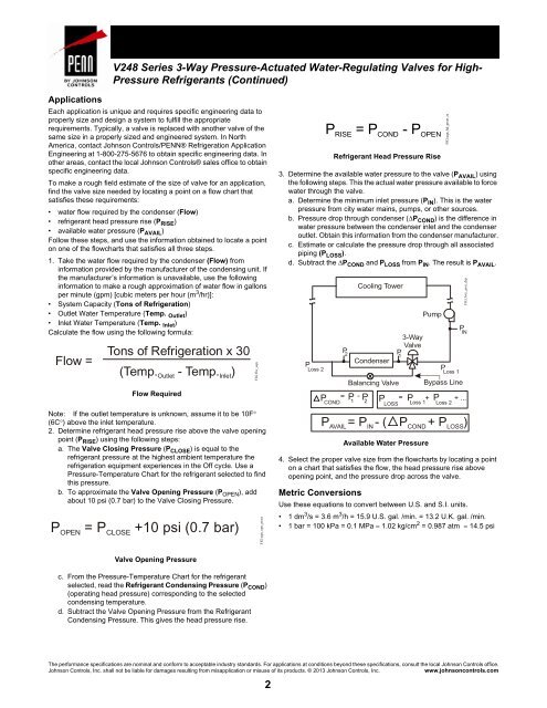
<strong>V248</strong> <strong>Series</strong> 3-<strong>Way</strong> <strong>Pressure</strong>-<strong>Actuated</strong> <strong>Water</strong>-<strong>Regulating</strong> <strong>Valves</strong> <strong>for</strong> High-<strong>Pressure</strong> Refrigerants (Continued)ApplicationsEach application is unique and requires specific engineering data toproperly size and design a system to fulfill the appropriaterequirements. Typically, a valve is replaced with another valve of thesame size in a properly sized and engineered system. In NorthAmerica, contact Johnson Controls/PENN® Refrigeration ApplicationEngineering at 1-800-275-5676 to obtain specific engineering data. Inother areas, contact the local Johnson Controls® sales office to obtainspecific engineering data.To make a rough field estimate of the size of valve <strong>for</strong> an application,find the valve size needed by locating a point on a flow chart thatsatisfies these requirements:• water flow required by the condenser (Flow)• refrigerant head pressure rise (P RISE )• available water pressure (P AVAIL )Follow these steps, and use the in<strong>for</strong>mation obtained to locate a pointon one of the flowcharts that satisfies all three steps.1. Take the water flow required by the condenser (Flow) fromin<strong>for</strong>mation provided by the manufacturer of the condensing unit. Ifthe manufacturer’s in<strong>for</strong>mation is unavailable, use the followingin<strong>for</strong>mation to make a rough approximation of water flow in gallonsper minute (gpm) [cubic meters per hour (m 3 /hr)]:• System Capacity (Tons of Refrigeration)• Outlet <strong>Water</strong> Temperature (Temp. Outlet )• Inlet <strong>Water</strong> Temperature (Temp. Inlet )Calculate the flow using the following <strong>for</strong>mula:Flow =Tons of Refrigeration x 30(Temp. Outlet - Temp. Inlet)Flow RequiredNote: If the outlet temperature is unknown, assume it to be 10F°(6C°) above the inlet temperature.2. Determine refrigerant head pressure rise above the valve openingpoint (P RISE ) using the following steps:a. The Valve Closing <strong>Pressure</strong> (P CLOSE ) is equal to therefrigerant pressure at the highest ambient temperature therefrigeration equipment experiences in the Off cycle. Use a<strong>Pressure</strong>-Temperature Chart <strong>for</strong> the refrigerant selected to findthis pressure.b. To approximate the Valve Opening <strong>Pressure</strong> (P OPEN ), addabout 10 psi (0.7 bar) to the Valve Closing <strong>Pressure</strong>.P OPEN = P CLOSE +10 psi (0.7 bar)FIG:flw_eqnFIG:eqn_opn_prssrP = P - PRISE COND OPENRefrigerant Head <strong>Pressure</strong> Rise3. Determine the available water pressure to the valve (P AVAIL ) usingthe following steps. This the actual water pressure available to <strong>for</strong>cewater through the valve.a. Determine the minimum inlet pressure (P IN ). This is the waterpressure from city water mains, pumps, or other sources.b. <strong>Pressure</strong> drop through condenser (ΔP COND ) is the difference inwater pressure between the condenser inlet and the condenseroutlet. Obtain this in<strong>for</strong>mation from the condenser manufacturer.c. Estimate or calculate the pressure drop through all associatedpiping (P LOSS ).d. Subtract the ΔP COND and P LOSS from P IN . The result is P AVAIL .PLoss 2P 2P = P -COND 1P 2Cooling TowerCondenserBalancing ValvePAvailable <strong>Water</strong> <strong>Pressure</strong>Pump4. Select the proper valve size from the flowcharts by locating a pointon a chart that satisfies the flow, the head pressure rise aboveopening point, and the pressure drop across the valve.Metric ConversionsUse these equations to convert between U.S. and S.I. units.• 1 dm 3 /s = 3.6 m 3 /h = 15.9 U.S. gal. /min. = 13.2 U.K. gal. /min.• 1 bar = 100 kPa = 0.1 MPa = 1.02 kg/cm 2 = 0.987 atm = 14.5 psiP 13-<strong>Way</strong>ValveFIG:eqn_hd_prssr_rsP Loss 1Bypass LineP P Loss 1 Loss 2FIG:3wy_prss_drpP IN= + + ...LOSSPAVAIL= PIN - ( PCOND+ PLOSS)Valve Opening <strong>Pressure</strong>c. From the <strong>Pressure</strong>-Temperature Chart <strong>for</strong> the refrigerantselected, read the Refrigerant Condensing <strong>Pressure</strong> (P COND )(operating head pressure) corresponding to the selectedcondensing temperature.d. Subtract the Valve Opening <strong>Pressure</strong> from the RefrigerantCondensing <strong>Pressure</strong>. This gives the head pressure rise.The per<strong>for</strong>mance specifications are nominal and con<strong>for</strong>m to acceptable industry standards. For applications at conditions beyond these specifications, consult the local Johnson Controls office.Johnson Controls, Inc. shall not be liable <strong>for</strong> damages resulting from misapplication or misuse of its products. © 2013 Johnson Controls, Inc.www.johnsoncontrols.com2


