WebWay Installation Guide Version 2c 3rd November ... - WebWayOne
WebWay Installation Guide Version 2c 3rd November ... - WebWayOne
WebWay Installation Guide Version 2c 3rd November ... - WebWayOne

You also want an ePaper? Increase the reach of your titles
YUMPU automatically turns print PDFs into web optimized ePapers that Google loves.
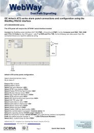
<strong>WebWay</strong> IP/GPRS & <strong>WebWay</strong> GPRS/PSTN <strong>Installation</strong> Manual<strong>WebWay</strong> GPRS/PSTN LPS I&HAS & <strong>WebWay</strong> GPRS/PSTN LPS FireI&HAS signalling configuration –Enhanced configuration profiles are available for Intruder and Hold-up systems when using the <strong>WebWay</strong> IP/GPRS. These shouldbe selected at the time of ordering the system and they will be configured into the <strong>WebWay</strong> GPRS/PSTN when it is commissionedto your selected ARC:When installed as a <strong>WebWay</strong> GPRS/PSTN I&HAS Signalling System the LPCB label will be identified by a tick in the 1022b/02 boxdenotes the approved hardware and configuration.Configuration- Grade 2 Alarm systems - LPS1277 Enhanced ATS4PLUS- Grade 3 Alarm systems - LPS1277 Enhanced ATS4PLUSFire signalling configuration- Fire Alarm Systems – LPS1277 Type 2 Alarm Transmission and fault warning routing equipmentImportant: When installed as a FIRE Signalling System a tick in the 22-5015 LPS Fire and 1022a/02 boxes denotes the approvedhardware and configuration will identify the CE label.Important: The <strong>WebWay</strong> IP/GPRS should either be installed in the associated EN54 compliant Fire Alarm Panel or an EN54-4compliant PSU.ConfigurationThe configuration settings for compliance with EN54-21 Type 2 are LPS 1277 EN54-21 Type 2 (Part number 1411AD155003)________________________________________________________________________________________________________Important notes:For further information of the signalling profiles and their parameters please refer to the section “Statutory information &Configuration profiles”.An ‘Auto Take-On’ procedure is described in this document and should be completed in conjunction with testing of alarm signallingto the ARC.If you require assistance from the <strong>WebWay</strong>One support group during the installation process you will need to provide the chipnumber, site ID and central station number. The number will have been provided by your ARC / Branch and is the number requiredfor the ‘Auto Take-on’ procedure<strong>WebWay</strong>One technical support is available between 08.30 am and 5.15 pm Monday to Friday.Any suspected faulty units should be notified to <strong>WebWay</strong>One technical support during the installation process.Contact for <strong>WebWay</strong> Technical support - 01635 231514<strong>WebWay</strong>One Ltd, 11 Kingfisher Court, Newbury, Berkshire, RG14 5SJTel 01635 231514: Email support@webwayone.co.ukPage 6
<strong>WebWay</strong> IP/GPRS & <strong>WebWay</strong> GPRS/PSTN <strong>Installation</strong> Manual<strong>Installation</strong> – equipment familiarisationPlease read this section and the appendixes prior to installing the <strong>WebWay</strong>; this manual includes the installation process for<strong>WebWay</strong> IP/GPRS and <strong>WebWay</strong> GPRS/PSTN.Check your <strong>WebWay</strong> installation package contains the following:<strong>WebWay</strong> IP/GPRS LPS I&HAS & <strong>WebWay</strong> IP/GPRS LPS FireIP/GPRS PCB fitted with plastic fixing baseT Bar antennaEthernet cableEthernet tamper shroud<strong>Installation</strong> manualWEBWAY IP/GPRS,28522,"?:"3;?80J53"0123145":1
<strong>WebWay</strong> IP/GPRS & <strong>WebWay</strong> GPRS/PSTN <strong>Installation</strong> ManualInterfaces, Push buttons, Switches, Display, Indicators, Inputs, Outputs, and PowerInterfaces - IP/GPRSEthernetAntennaSerial RS232 – 3 wires: Transmit, Receive & Return path groundSerial RS485 – 3 wires: A, B, & Return path groundSerial TTL – 3 wires: Transmit, Receive & Return path groundConsole portInterfaces – GPRS/PSTNIn addition to IP/GPRS interfaces:Telephone line – a and bExtension wiring – a and bPush ButtonsA, B, & CDIP SwitchesSwitch Description NotesSwitch 1IP/GPRS - force Ethernet FAILGPRS/PSTN - force PSTN FAILReturn to OFF after test procedureSwitch 2 Force GPRS FAIL Return to OFF after test procedureSwitch 3 MENU Factory setting – do not changeSwitch 4 DISP Factory setting – do not changeSwitch 5 MODE Factory setting – do not changeSwitch 6 RUN/BOOT Factory setting – do not changeSwitch 7 33/66 Set to ON when using the Modem Capture and Audio Capture moduleSwitch 8 HIGH/LOW Factory setting – do not changeSwitch 9 SOFT Factory setting – do not changeSwitch 10 TERM Factory setting – do not changeDisplayStarburst displayIndicatorsLegend Indicator DescriptionPNLEXTATSMSGSMGPanel indicatorExternal port interfaceindicatorPath and interface statusMessage statusCommission statusEthernet dataShows the data flow for the serial alarm panel interface- Red for data from the alarm panel to the <strong>WebWay</strong>- Green for data from the <strong>WebWay</strong> to the alarm panelShows the data flow for the optional serial alarm panel interface- Red for data from the external device to the <strong>WebWay</strong>- Green for data from the <strong>WebWay</strong> processor to the external deviceShows the status of each transmission interface and path.The indicator flashes once for each path followed by a gap.Each flash provides the following status indications:Green – Good path on good interfaceOrange – Bad interfaceRed – Bad path (no communication with ARC) but interface goodMessage queue status indicationIndicates the status of the queue of messages being sent to the ARCRed – Messages are queued and have not been sentGreen – Messages have been sent but not acknowledgedOrange – Messages waiting to be sent plus messages sent and waiting to beacknowledgedOff – No messages waiting to be sent or waiting to be acknowledgedIndicates the configuration and commission status of the <strong>WebWay</strong>Flashing Green (sometimes with a hint of orange) – CommissionedFlashing Orange – Initialising, system not ready yetRed / Green Alternate – Not commissionedFlashing Red – Not CommissionedGreen on – 10BaseTGreen off – 100BaseTRed - Data activity to and from the LAN<strong>WebWay</strong>One Ltd, 11 Kingfisher Court, Newbury, Berkshire, RG14 5SJTel 01635 231514: Email support@webwayone.co.ukPage 8
<strong>WebWay</strong> IP/GPRS & <strong>WebWay</strong> GPRS/PSTN <strong>Installation</strong> ManualPIN inputsPINS 1-8 End of line or simple PINS, PINS 9-16 simple PINSPINS – Tamper, Mains Fail, Battery FailBIAS voltage +/-PIN OutputsPIN outputs 1, 2 & 3Reference voltages A+ Nominal 12 volts or 24 volts depending on application; A- 0 voltsPowerInputs + PWR - adjacent to the Ethernet connector<strong>WebWay</strong>One Ltd, 11 Kingfisher Court, Newbury, Berkshire, RG14 5SJTel 01635 231514: Email support@webwayone.co.ukPage 9
<strong>WebWay</strong> IP/GPRS & <strong>WebWay</strong> GPRS/PSTN <strong>Installation</strong> Manual<strong>Installation</strong> process for <strong>WebWay</strong> IP/GPRS & <strong>WebWay</strong> GPRS/PSTNNote: For Fire Type 1 or Type 2 applications CE Fire label should be fixed to the unit prior to installation.The <strong>WebWay</strong> is fitted with a plastic base for installation in your chosen Alarm Panel using the adhesive pads provided. In somecases the <strong>WebWay</strong> will be delivered in its own-boxed PSU. Either fix the <strong>WebWay</strong> into the Alarm Panel with the adhesive pads orfix the Boxed system to the wall.Location of equipment – <strong>Installation</strong> to BS8243:2010It is essential that the signalling equipment be sited in an area where access will result in a confirmed activation. Signallingequipment should not be located in an area configured as an alarm entry route.Antenna installation – part 1Connect the Antenna cable to the <strong>WebWay</strong> and temporarily locate the T-Bar Antenna away from the enclosure. Part 2 of theAntenna installation is described after the unit is power on.<strong>WebWay</strong> IP/GPRS - connecting the Ethernet cableConnect the Ethernet cable to the RJ45 port of the <strong>WebWay</strong> and an allocated RJ45 connection on the clients Ethernet switch orrouter and ensure the Ethernet cable shroud is fitted to protect against accidental removal.Note: Secure the Ethernet cable by pushing the shroud over the RJ45 plug and crop just beyond the shoulder of the locking tag.Move the cable shroud over the RJ45 Plug to prevent accidental cable removal.Dedicated IP path configurationPrior to <strong>Installation</strong> the following signalling information is required for the Auto Take On configuration process.The ARC selected for notification of AlarmsLocal IP addressing:Option 1 - DHCP – automatic allocation of IP addressesOption 2 - Static IP Address - IP Address, Subnet mask, and Default GatewayClient static IP Network and Firewall configuration requirementsIMPORTANT. Prior to installation you will need to ensure the clients IT department has provided a network connectionpoint, (Power socket if required), the IP address information, and opened the appropriate Firewall ports. (If you need anyadvice regarding Firewalls you should contact <strong>WebWay</strong> support on 01635 231514.)The <strong>WebWay</strong> can be installed with DHCP or Static IP addresses. Where a static IP is selected the IP Address, Subnet mask, andDefault Gateway are required.To assist the client to configure the Firewall the following information is provided:The <strong>WebWay</strong> IP/GPRS is installed at the remote premises and communicates, via the customer network/firewall, with MonitoringCentre Transceivers (MCTs), located in the alarm-receiving centre (ARC).For all IP traffic the MCTs at the ARC listen for the Encrypted Alarms and Polling messages on UDP port 50561. The <strong>WebWay</strong>initiates communication over any IP path and the return path is reliant on state-full dynamic port mapping (NAT) at the securepremises or fixed routing/port mapping if required by the supervised premises client.Additional support diagnostics are available if a local PING can be sent from the <strong>WebWay</strong> device to the on site router (or othernetwork devices).System transmission protocol is UDP/IP. All data is encrypted using the AES standard with a 128-bit key and 256 bit hash codeand sequenced. The data bandwidth required for the Signalling System for Alarms and Polling is160 bytes (round trip includingalarm and acknowledgement). Polling frequency is every 30 seconds from each connectionAlternative data delivery options<strong>WebWay</strong> traffic may be delivered to the ARC over VPN or dedicated links on agreement.<strong>WebWay</strong> GPRS/PSTN - connecting the Telephone LineConnect the telephone line to terminals La and Lb on the PSTN module.PSTN Operational NotesIt is advised that you carry a Butt phone when installing the Airway solution in case line checks are requiredThe line must not be configured to withhold CLI on outgoing calls‘Call Barring’ MUST NOT be enabled on the line.If a prefix of 9 to dial out or carrier pre-selection (1280) is needed we can modify the unit to use those prefixesIf it’s connected to the PSTN service of a Broadband Circuit then an appropriate DSL filter MUST be fitted.<strong>WebWay</strong>One Ltd, 11 Kingfisher Court, Newbury, Berkshire, RG14 5SJTel 01635 231514: Email support@webwayone.co.ukPage 10
<strong>WebWay</strong> IP/GPRS & <strong>WebWay</strong> GPRS/PSTN <strong>Installation</strong> ManualConnecting the <strong>WebWay</strong> to the Alarm SystemAlarm Panel connection – SerialConnect the <strong>WebWay</strong> using the appropriate serial connection to the alarm panel and configure the panel according to theinstructions detailed in the <strong>WebWay</strong> document ‘<strong>WebWay</strong> alarm panel configuration’. <strong>Installation</strong> details may be obtained from<strong>WebWay</strong>One for all major Alarm Panels. The serial connections are 3 wires, which includes a return path ground from the AlarmPanel serial interface.Alarm Panel connection – PINSPINS 1-16IMPORTANT: Fire applicationsWhen used in Fire applications PIN 1 (Fire Alarm) and PIN2 (Fire fault or trouble) are always programmed as EOL. PIN Inputs 3-8can be programmed as simple HIGH/LOW inputs or END OF LINE (EOL) and PINS 9-16 are always programmed as simpleHIGH/LOW inputs.IMPORTANT: Fire Alarm Configuration - to comply with requirements of EN54-21 7.4.1 a hard wired fire alarm input mustuse PIN 1. The <strong>WebWay</strong> will ensure that the Fire Alarm will be transmitted before any other fire fault event where multiple Alarmsand Faults are generated at the same time.I&HAS applications: When used in I&HAS applications PIN Inputs 9-16 are always programmed as simple high low inputs andPIN Inputs 1-8 can be individually programmed as END OF LINE (EOL) or simple HIGH/LOW inputs.PINS – End of lineALARM PANELOUTPUT10K0V4K7WEBWAYPIN X0VHard wired Inputs 1-8 configured as ‘end of line’ (EOL)Alarm state 10k +/- 5%Restore state 14k7 +/- 5%Open circuitLoop > 100k ohmsShort circuitLoop < 5 ohmsTamper conditions - Loop between > 5 ohms & < 10k ohms -5%- Loop between > 10k ohms + 5% & < 14k7ohms -5%- Loop between > 14k7 ohms + 5% & < 100kohmsIf required the alarm and restore conditions may be reversed in the SPTconfigurationPINS – Bias highALARM PANELOUTPUTWEBWAYPIN XBIAS HIGHHard wired Inputs 1-16 configured as simple high inputsInput threshold high to low 2.0V DC (maximum Input voltage: 30V DC)If required the alarm and restore conditions may be reversed in the SPTconfiguration0V0VPINS – Bias low+VOUTPUTWEBWAYPIN XHard wired Inputs configured as simple low inputsInput threshold low to high 4.0V DC (maximum Input voltage: 30V DC)If required the alarm and restore conditions may be reversed in the SPTconfigurationALARM PANELBIAS LOW0V0VHard wired PIN InputsPIN Input - Tamper configured as for simple low or high inputsPIN Input - Battery fail configured as for simple low or high inputsPIN Input - Mains fail configured as for simple low or high inputs<strong>WebWay</strong>One Ltd, 11 Kingfisher Court, Newbury, Berkshire, RG14 5SJTel 01635 231514: Email support@webwayone.co.ukPage 11
<strong>WebWay</strong> IP/GPRS & <strong>WebWay</strong> GPRS/PSTN <strong>Installation</strong> ManualAlarm panel connection – Modem CaptureThe Modem capture module may be used for Intruder & Hold up alarm signalling, Upload/Download and remote servicing. Detailsare provided in the document ‘<strong>WebWay</strong> alarm panel configuration’Modem capture moduleIMPORTANT NOTE: 1 When using the Modem capture in association with a fire system Fire Alarm, Fire Fault or Troublemessages must be transmitted using the PIN interfaces.IMPORTANT NOTE: 2 Remove power before fitting or removing the module.- Before fitting the Modem Capture module set the OSC jumper to 66Mhz.- Fit the Modem capture module onto the 15-pin PL1 connector and fix to the steel spacing pillar on the main board using the screwprovided.- Connect the <strong>WebWay</strong> to the Modem capture module and the alarm panel. You will be required to configure the panel accordingto the instructions detailed in the <strong>WebWay</strong> document ‘Alarm panel interconnections and programming’ – This document isavailable from <strong>WebWay</strong>One; if you need assistance call <strong>WebWay</strong> support on 01635 231514.WEBWAY IP/GPRS + MODEM CAPTURE OPTION BOARD,28522,"7H12"/H88123"367"637",83"598":24"ABC=>3:4,?"ON1 2 3 4 5 6 7 8 9 10=>:"3;>80I53"SIM0123145":1285
<strong>WebWay</strong> IP/GPRS & <strong>WebWay</strong> GPRS/PSTN <strong>Installation</strong> ManualReporting ATS faults to the CIEWhen Installing the <strong>WebWay</strong> to meet EN54-21, EN50131-1 and PD6662 standards the following connections should be madebetween the <strong>WebWay</strong> and the Alarm System.Fault output relay Signal DescriptionEN54-21 Fire modePIN output 1 SparePIN output 2 Fire Alarm Acknowledged Received acknowledgement from the fire alarm receiving centrePIN output 3EN50131 I&HAS mode 1PIN output 1Fault WarningGPRS failurePIN output 2Ethernet (IP/GPRS) orPSTN failure (GPRS/PSTN)PIN output 3 SpareEN50131 I&HAS mode 2PIN output 1PIN output 2PIN output 3Communications failure/Dual PathfailureSpareSpareA Fault warning signal will be generated when one of thefollowing faults is detected1 Failure to receive an acknowledgement to a Fire AlarmMessage within 100s2 Failure of the <strong>WebWay</strong> IP/GPRS or <strong>WebWay</strong> GPRS/PSTN orpower.3 Failure of the Alarm Transmission Network (all paths failed)4 A PIN fault (Open Circuit, Short Circuit etc.)Single Path alarm presented after the elapsed reporting timesdefined in Table 11 – enhanced ATS 4+ and Enhanced ATS 5+Single Path alarm presented after the elapsed reporting timesdefined in Table 11 – enhanced ATS 4+ and Enhanced ATS 5+Catastrophic failure of the Alarm transmission SystemPower connectionEnsure the Alarm System power is OFF before connecting the <strong>WebWay</strong>.Connect the <strong>WebWay</strong> PWR + and – terminals to the power supply of the alarm panel +v and –v.Restore power to the Alarm System.The <strong>WebWay</strong> will automatically initiate a start-up sequence and on completion the GSM signal strength will be shown on thedisplay; represented by a number between 1 - 9 & A (representing a maximum value of 10).Antenna installation – part 2Locate the T-Bar Aerial in a position that provides the maximum GPRS signal (1 being the lowest and A, the highest) and fix theAntenna using the self-adhesive pad.Note: Do not fix the T-Bar Antenna to the enclosure<strong>WebWay</strong> configurationThe <strong>WebWay</strong> will normally have been pre configured for your installation and commissioning will automatically commence afteryou have entered the site ID and the unit is reset.Entering the Site IDEnsure the <strong>WebWay</strong> displays a stable GSM signal strength reading and proceed to enter the Site ID using the display andconfiguration buttons as follows:Tap button A until menu option ‘d’ is displayedPress and hold the ‘C’ button until ‘_’ is displayedTapping the ‘A’ button decreases the displayed number, and tapping the ‘B’ button increases the displayed number. Use the A andB buttons to select the first number of the site ID. When the number appears on the display, press the ‘C’ button to enter - this willreturn the display to ‘_’Follow the same process to enter the remaining numbers of the site IDAfter the final number of the site ID has been entered press the ‘C’ button a second time. A moving circle will be displayed followedby a return to menu option ‘d’Check that you have correctly entered the site ID by pressing the ‘C’ button and observing the readoutIMPORTANT: If you have entered the ID incorrectly, when the system returns to the signal strength display re-enter theSite ID.Commissioning and Automatic Configuration – AUTO TAKEONPress the RESET button located at the top left of the board (above the display) to finalise the commissioning – it will take up to 5minutes to complete the commissioning and automatic configuration of the <strong>WebWay</strong>.<strong>WebWay</strong>One Ltd, 11 Kingfisher Court, Newbury, Berkshire, RG14 5SJTel 01635 231514: Email support@webwayone.co.ukPage 13
<strong>WebWay</strong> IP/GPRS & <strong>WebWay</strong> GPRS/PSTN <strong>Installation</strong> ManualTesting Alarm signals with the ARCWhen the <strong>WebWay</strong> AUTO TAKEON is completed you should send test alarms to your ARC.If the ARC successfully receives the alarms the system is fully commissioned.If the ARC does not receive the correct test alarms contact <strong>WebWay</strong>One Technical Support on 01635 231514.Alarm Transmission Path tests with the ARC - ManualTo simulate a failure of the Ethernet path, PSTN Telephone line, or the GPRS path select the following switch positions:DIP switch settings0&$&+'7#>7!*+"0$'?'>7$-%*@'$()'($)'*+$'&,+'-#%'>7$-%*@'!"#;7)
<strong>WebWay</strong> IP/GPRS & <strong>WebWay</strong> GPRS/PSTN <strong>Installation</strong> ManualRemote ServicingRemote servicing of Alarm Panels and the Alarm Transmission System is described in the new Standard DD263:2010The <strong>WebWay</strong> IP/GPRS and the <strong>WebWay</strong> GPRS/PSTN are connected to the secure premises via the <strong>WebWay</strong> MCTs at the ARC.<strong>WebWay</strong> Remote Manager provides secure access software, permitting an Alarm System management package to remotelyaccess an Alarm System and the <strong>WebWay</strong> from a secure premise using a secure computer. The access process complies with allthe requirements of initialization, authorization, authentication of communication, and information security defined in DD263,section 4.2 C) 3. The Information and Substitution security meets I3, S2 and the security requirements of EN50136-1-5: 2006 for IPnetworksAlarm Transmission Path tests with the ARC – Automatic Remote (DD263)The ARC or the Alarm Company may initiates the required tests using the <strong>WebWay</strong> Remote Manager, and results areautomatically logged and displayed on the <strong>WebWay</strong> Command Centre.Testing process:The test is initiated by accessing the ʻSite Displayʼ screen for the required location on the <strong>WebWay</strong> Command Centre.The Diagnostics screen is selected to initiate a check of each ATS transmission path. The process will confirm when the remotechecks have been completed.The path checks are displayed at the <strong>WebWay</strong> Command Centre. The checks may also be displayed on the AnnunciationEquipment at the ARC (This is a setting in the <strong>WebWay</strong> IP/GPRS and <strong>WebWay</strong> GPRS/PSTN configuration profiles).There are four paths checked during the process:<strong>WebWay</strong> IP/GPRS<strong>WebWay</strong> Ethernet path through Broadband Network to MCT1/ARC 1<strong>WebWay</strong> Ethernet path through Broadband Network to MCT2/ARC 2<strong>WebWay</strong> GPRS path through GPRS Network to MCT1/ARC 1<strong>WebWay</strong> GPRS path through GPRS Network to MCT2/ARC 2<strong>WebWay</strong> GPRS/PSTN<strong>WebWay</strong> GPRS path through GPRS Network to MCT1/ARC 1<strong>WebWay</strong> GPRS path through GPRS Network to MCT2/ARC 2<strong>WebWay</strong> PSTN path through Telephone Network to MCT1/ARC 1<strong>WebWay</strong> PSTN path through Telephone Network to MCT2/ARC 2This process fully complies with the requirements of PD 6662:2004 and DD 263:2010 and will operate in any system withoutreliance of any reciprocal software need in the alarm panel.Remote Management of Alarm PanelsThe ARC or the Alarm Company initiates a secure connection using the <strong>WebWay</strong> Remote Manager and the Alarm Companymanagement software to access the Site and the Panel. Details of the Engineer, the Secure Computer and the Time and Date arerecorded in the system.For further information on Remote Management and Maintenance of Alarm Panels contact <strong>WebWay</strong>One<strong>WebWay</strong>One Ltd, 11 Kingfisher Court, Newbury, Berkshire, RG14 5SJTel 01635 231514: Email support@webwayone.co.ukPage 15
<strong>WebWay</strong> IP/GPRS & <strong>WebWay</strong> GPRS/PSTN <strong>Installation</strong> ManualAnnex A - Configuration profiles<strong>WebWay</strong> IP/GPRS and <strong>WebWay</strong> GPRS/PSTN have been tested and certificated to LPS1277 for enhanced ATS performance.The Revised Table 10 shown below permits stakeholders to select enhanced option C ATS 5 and enhanced options ATS4Plus.Alarm Transmission Systems for use with Grade 2, 3, and 4 I&HAS. When an option is selected the profile is automaticallydownloaded to the <strong>WebWay</strong> when connected to the chosen Alarm Receiving Centre. The ARC or <strong>WebWay</strong>One will only makechanges to a configuration on instruction in writing from the End User and the associated Alarm Company.Configuration profiles for Intruder and Hold-Up Alarm Systems<strong>WebWay</strong> IP/GPRSThe IP/GPRS has been tested and certificated by LPCB to LPS1277 for enhanced ATS performance criteria higher than currentlyavailable in Table 11 (EN50131-1:2006+A1:2009)The standard profile for IP/GPRS is Dual Path Enhanced ATS5 where the reporting time of the secondary path steps up to 3minutes when the primary is failed and the system will detect a catastrophic ATS failure or attack within 3.5 minutes. A uniquefeature of the <strong>WebWay</strong> IP/GPRS is the system software that provides availability figures for the monitoring and management everypath of every ATS to 99.8%.<strong>WebWay</strong> GPRS/PSTNThe GPRS/PSTN has been tested and certificated by LPCB to LPS1277 for enhanced ATS performance criteria higher thancurrently available in Table 11 (EN50131-1:2006+A1:2009)The standard profile for GPRS/PSTN is Dual Path Enhanced ATS4+ where the reporting time of the secondary path steps up to 10minutes when the primary is failed and the system will detect a catastrophic ATS failure or attack within 11 minutes. A uniquefeature of the <strong>WebWay</strong> IP/GPRS is the system software that provides availability figures for the monitoring and management everypath of every ATS to 99.8%.Configuration profiles for Fire alarm transmission and fault warning routing equipment<strong>WebWay</strong> IP/GPRSThe IP/GPRS has been tested and certificated by LPCB under LPS1277 for Fire Alarm System to the ATS Type 1 requirements ofEN54-21:2006 Annex A Table A1. See revised Table 11.The ATS criteria chosen, as the standard profile for IP/GPRS is Dual Path ATS Fire Type 1 where the reporting time of thesecondary path steps up to 90 seconds when the primary path is failed and the system will detect a catastrophic ATS failure orattack within 3 minutes. A unique feature of the <strong>WebWay</strong> IP/GPRS is the system software that provides availability figures for themonitoring and management every path of every ATS to 99.8%.<strong>WebWay</strong> GPRS/PSTNThe GPRS/PSTN has been tested and certificated by BRE under LPS1277 for Fire Alarm System to the ATS Type 2 requirementsof EN54-21:2006 Annex A Table A1. See revised Table 11. The standard profile for GPRS/PSTN is Dual Path Enhanced ATS4+where the reporting time of the secondary path steps up to 10 minutes when the primary is failed and the system will detect acatastrophic ATS failure or attack within 11 minutes.A unique feature of the <strong>WebWay</strong> GPRS/PSTN is the system software that provides availability figures for the monitoring andmanagement every path of every ATS to 99.8%.Revised Table 10 - EN50131-1:2006+A1:2009 for enhanced ATS options C4+ and C5Grade 2 (I&HAS) Grade 3 (I&HAS) Grade 4 (I&HAS)NotificationEquipmentRemotelypowered AudibleWDSelf-poweredAudible WDMain ATSAdditional ATSATS Dual PathCOptions Options OptionsCATS4PLUS<strong>WebWay</strong>GPRSPSTNCATS 5<strong>WebWay</strong>IPGPRSCCATS4PLUS<strong>WebWay</strong>GPRSPSTNCATS 5<strong>WebWay</strong>IPGPRSCCATS 5<strong>WebWay</strong>IPGPRSOp Op Op Op Op Op Op OpOp Op Op Op Op Op Op OpATS2ATS1ATS4PLUS ATS 5ATS4PLUS ATS 5EnhancedATS4PLUSEnhancedATS 5ATS4ATS3ATS4PLUS ATS 5ATS4PLUS ATS 5EnhancedATS4PLUSEnhancedATS 5ATS5ATS4ATS 5ATS 5EnhancedATS 5Note: Single path options and Grade 1 I&HAS have been removed for clarity<strong>WebWay</strong>One Ltd, 11 Kingfisher Court, Newbury, Berkshire, RG14 5SJTel 01635 231514: Email support@webwayone.co.ukPage 16
<strong>WebWay</strong> IP/GPRS & <strong>WebWay</strong> GPRS/PSTN <strong>Installation</strong> Manual<strong>WebWay</strong>One Ltd, 11 Kingfisher Court, Newbury, Berkshire, RG14 5SJTel 01635 231514: Email support@webwayone.co.ukPage 17
<strong>WebWay</strong> IP/GPRS & <strong>WebWay</strong> GPRS/PSTN <strong>Installation</strong> ManualRevised Table 11 - EN50131-1:2006+A1:2009Including: I&HAS - LPS enhanced ATS5 & LPS enhanced ATS4 PLUSIncluding: FIRE - LPS EN54-21 Type 1 & LPS EN54-21 Type 2The revised table 11 is shown below and outlines the key parameters for the advanced performance of the selected signallingsystem. Highlighted performance criteria illustrate the <strong>WebWay</strong>One advanced signalling solutions certificated by the LPCB.PerformanceCriteriaTransmissionTimeTransmissionTime MaxReportingTime (RT)Main ATPReporting time ofadditional pathMain ATP goodReporting time ofadditional pathMain ATP failedReporting timeCatastrophicFail ATP 1& 2SubstitutionSecurityInformationSecurityATS AvailabilityATS 1D1120sM1480sT225hNotrequiredS0 !0NotrequiredATS 2D260sM2120sT225hNotrequiredS0 !0NotrequiredATS 2 + ATS 1D260sM2120sT2 25hT225hT225 hNotrequiredS0 I0NotrequiredATS 3D260sM2120sT2 25hNotrequiredS1 I1NotrequiredATS 4D260sM2120sT3300mNotrequiredS1 I2NotrequiredATS 4 + ATS 3D260sM2120sT3300mT225hT3300 mNotrequiredS1 I2Notrequired<strong>WebWay</strong> GPRS/PSTN LPS I&HASLPS EnhancedATS4PLUSDual PathD360 sM3120 sT3+10 mT324 hT3+10 m11 m S2 I3 A4LPS enhanced ATS4PLUS = Dual Path ATS with 10 minute reporting time, stepped up reporting of secondary path failure,and 11 minute reporting time for catastrophic failure of both paths and A4 requirement for ATS availability.<strong>WebWay</strong> GPRS/PSTN LPS FireLPS ATS FireEN54-21 Type 2D310 sM330 sT3+10 mT324 hT324 hT311 mS2 I3 A4ATS 5D320sM360sT4180sNotrequiredS2 I3NotrequiredATS 5 + ATS 4D320sM360sT4180sT4+300mT4+300mNotrequiredS2 I3Notrequired<strong>WebWay</strong> IP/GPRS LPS I&HASLPS EnhancedATS5Dual PathD420 sM360 sT4180 sT330 mT4180 s210 s S2 I3 A4LPS enhanced ATS5 = Dual Path ATS with 3 minute reporting time, stepped up reporting of secondary path failure, and3 .5 minute reporting time for catastrophic failure of both paths and A4 requirement for ATS availability<strong>WebWay</strong> IP/GPRS LPS FireLPS ATS FireEN54-21 Type 1D410 sM320 sT590 sT330 mT590 s180 s S2 I3 A4ATS 6D410sM420sT620sNotrequiredS2 I3Notrequired<strong>WebWay</strong>One Ltd, 11 Kingfisher Court, Newbury, Berkshire, RG14 5SJTel 01635 231514: Email support@webwayone.co.ukPage 18
<strong>WebWay</strong> IP/GPRS & <strong>WebWay</strong> GPRS/PSTN <strong>Installation</strong> ManualAnnex B - LPS 1277 <strong>Installation</strong> procedures<strong>Installation</strong> guidance for LPCB approved supervised premises transceivers (SPT) connected to Intrusion & Hold up AlarmSystems (I&HAS)This ‘Best Practice’ guidance on installation practices will help enhance general Alarm Transmission System (ATS) security/resilience, avoid undue (false) path failure reports and reduce customer inconvenience.Important Notes1 A claim to have installed LPCB approved SPT will be invalid if this guidance has not been followed.2 Within this guidance the word ‘shall’ indicates a mandatory requirement. Use of the word ‘should’ indicates a requirement unlesspractical constraints prevent compliance.<strong>Installation</strong> (alarm company) InformationLocation and alarm protection of the Supervised Premises Transceiver (SPT)i) The SPT part of the Alarm Transmission Equipment (ATE), shall be located within the I&HAS Control and Indicating Equipment(CIE), or within an enclosure that shares the same mains power supply, and has the same level of battery back up and tamperprotection, as is required for the associated CIE.ii) The location of the CIE, or other enclosure, containing the SPT;- shall, when installed as part of a new I&HAS; be in an area provided with ‘direct alarm protection’ a) and be located where it is notvisible to, or readily accessible by, members of the public.- should, when retro-fitted to a pre-existing I&HAS; be in an area provided with ‘direct alarm protection’ a) and be located where it isnot visible to, or readily accessible by, members of the public.Alarm protection of Site Network Equipmenti) ‘Site Network Equipment’ b) that can be switched off or which has a locally or remotely accessible and changeable function, (e.g.a telephone switchboard or IP router), together with Alarm Transmission Path (ATP) aerials* and network access terminationpoints, shall be located in an area provided with ‘direct alarm protection’ a) .ii) Other ‘Site Network Equipment’ b) , for example intermediate junction boxes, should be provided with ‘direct alarm protection’ a) .Where an ATP aerial cannot be located in an area readily provided with ‘direct alarm protection’ a) and still achieve therecommended minimum signal strength for adequate performance, it may be installed elsewhere (preferably indoors but otherwiseoutdoors), subject to positioning it where its discovery and/or ready access by intruders is considered unlikely.Connections between the SPT and Site Network Equipment b)i) Any radio based ATP shall have a cable connection between the SPT and the required aerial, with all cable termination points,including those at any intermediate connections, using termination components (or housings) that protect against cable removalwithout the use of a tool.ii) Any landline based ATP shall have a cable connection between the SPT and the first suitable alarm transmission networktermination point within the premises. This shall be made in one continuous run and use termination components (or housings) thatprotect against cable removal without the use of a tool.The connection to the alarm transmission network shall be made in such a manner that where non-alarm relatedapparatus/services are also connected to that network, they do not prevent, or interfere with, the correct operation of the ATS.Notes.a)The phrase 'direct alarm protection' shall mean that sufficient detection devices are installed to ensure that, when the I&HAS isset, access to the protected equipment results in a full (e.g. a ‘confirmed’) alarm condition. Where an I&HAS uses a time delayedentry/exit route as part of the facility for unsetting, detection devices programmed to act as entry/exit route detection shall not beregarded as providing ‘direct protection’.b)The phrase ‘Site Network Equipment’ shall be regarded as all equipment installed within the alarmed premises through whichsignals from the SPT to the alarm transmission network beyond the perimeter of the premises are transmitted. For example, nonalarmdedicated (shared use) IP routers, telephone switchboards/Private Automatic Branch Exchanges (PABX), network accesstermination points, ATP aerials and communication network junction boxes/switches.ARC/ATS message holdingWhere the Alarm Receiving Centre (ARC) &/or ATS provider offers, or requests use of, a facility to block the receipt of, or holdinformation relating to, ATS fault notification signals or messages pending receipt of further alarm information (e.g. pending thedesignation of a confirmed alarm as per BS 8243), agreement to such an action shall be confirmed in writing by the customer (enduser); with the relevant notification stating that this action is compatible with the risk assessment and/or the requirements of anyinterested party, for example an insurer.In such cases the installer shall make suitable arrangements, which shall be confirmed in writing, for the customer to be alerted toany such ATS fault notification signals/messages when their alarm system is next unset, or after a period of 96 hours, whichever isthe sooner.Customer (end user) InformationInstallers shall advise the customer: -1 - of any potential for normal ATS functions, including normal or ‘stepped up’ checking of ATS availability (e.g. by sending testsignals), which could interfere with, or prevent use of, any non-alarm related apparatus/services connected to a telephone lineshared with the ATS. In such cases customers should be recommended to consider use of an ex-directory 'In Coming Calls Barred'(ICCB) telephone line dedicated to ATS use.2 - of the adverse effect on reliable operation of their intruder alarm system that may result where ‘Site Network Equipment’ b) usedby the ATS:-- could have its correct operation/settings locally or remotely accessed and changed/disabled, for example a non-alarm dedicated(shared use) IP router. In such cases customers should be recommended to consider protection against unauthorised access by<strong>WebWay</strong>One Ltd, 11 Kingfisher Court, Newbury, Berkshire, RG14 5SJTel 01635 231514: Email support@webwayone.co.ukPage 19
<strong>WebWay</strong> IP/GPRS & <strong>WebWay</strong> GPRS/PSTN <strong>Installation</strong> Manualthe use of an access password (not the factory default) and, if their equipment has wireless connectivity having the wirelessnetwork Access Point Name (APN) hidden.- would cease to work in the event of loss of mains power; for example a Private Automatic Branch Exchange (PABX) or non-alarmdedicated (shared use) IP Router. In such cases customers should be recommended to consider protecting the power supplyagainst disconnection by use of an unswitched fused spur connection or by having such equipment or its power supplyconnections located in an area/room to which unauthorised access is restricted.3 - of the adverse effect on reliable operation of their intruder alarm system that may result from cessation of any communicationservice(s) necessary for correct operation of the ATS; for example telephony services such as ‘three way calling’ (Star Services) oraccess to internet services (via an ISP). In such cases customers should be recommended to take steps to ensure that availabilityof these services is maintained at all times when their alarm system is likely to be in use.4 - that, where the performance of the SPT is capable of being changed after installation, such changes shall be confirmed inwriting by the customer; with the relevant notification stating that any such change is compatible with the risk assessment and/orthe requirements of any interested party, for example an insurer.<strong>WebWay</strong>One Ltd, 11 Kingfisher Court, Newbury, Berkshire, RG14 5SJTel 01635 231514: Email support@webwayone.co.ukPage 20
<strong>WebWay</strong> IP/GPRS & <strong>WebWay</strong> GPRS/PSTN <strong>Installation</strong> ManualAnnex CEC Declaration of ConformityIn accordance with EN ISO 17050-1:2004We <strong>WebWay</strong>One Ltdof11 Kingfisher Court, Hambridge Road, Newbury, Berkshire, RG14 5SJin accordance with the following Directive(s):2006/95/EC2004/108/EEC1999/5/EC89/106/EECCPDThe Low Voltage DirectiveThe Electromagnetic Compatibility DirectiveR&TTE DirectiveConstruction Products Directive (CPD)hereby declare that:Equipment<strong>WebWay</strong> IP/GPRS, <strong>WebWay</strong> GPRS/PSTNModel number22- 5072 (<strong>WebWay</strong> IP/GPRS), 22- 5085 (<strong>WebWay</strong> GPRS/PSTN)Is in conformity with the applicable requirements of the following documentsAlarm Transmission Systems, applications and safety standardsEN50136-1-1: 1998+A2:2008EN50136-1-2: 1998EN50136-1-3: 1998EN50136-1-4: 1998EN50136-2-1: 1998EN50136-2-2: 1998EN50136-2-3: 1998EN50136-2-4: 1998EN50136-1-5 : 1998EN 50131-1:2006+A1: 2009EN54-21: 2006EN54-2: 2006General requirements for alarm transmission systemsRequirements for systems using dedicated alarm pathsRequirements for systems with digital communicators using the public switched telephonenetworkRequirements for systems with voice communicators using the public switched telephonenetworkGeneral requirements for alarm transmission equipmentRequirements for equipment used in systems using dedicated alarm pathsRequirements for equipment used in systems with digital communicators using the publicswitched telephone networkRequirements for equipment used in systems with digital communicators using the publicswitched telephone networkRequirements for PSNGeneral requirements for AlarmPart 21 - Alarm Transmission and fault warning routing equipmentPart 2 – Control and indicating equipmentEN54-21: 2006 Part 4 – Power supply equipment. Incorporating Amendment No. 1: 2002PD 6662: 2010BS 8243: 2010DD 263: 2010BS 8418: 2010BS 5979: 2001BS EN 60950-1TBR21Scheme for the application of European standards for intrusion and hold up alarm systems<strong>Installation</strong> and configuration of I&HAS designed to generate confirmed alarm conditions – Codeof practiceI&HAS – Commissioning, maintenance and remote support – Code of practice<strong>Installation</strong> and remote monitoring of detector-activated CCTV systems – Code of practiceRemote centres receiving signals from fire and security systems – Code of practiceSafety of information technology equipmentPublic Switched Telephone Network StandardThe product is compliant with the following emissions standards:Description General Standard Referenced StandardRadiated disturbanceConducted disturbance, ac portConducted disturbance, telecom portMains harmonicsEN 61000-6-3:2007EN 55022:2006 Class BEN 61000-3-2:2006 Class AMains voltage flicker (d max = 4%) EN 61000-3-3:1995 including A1: 2001 & A2:2005<strong>WebWay</strong>One Ltd, 11 Kingfisher Court, Newbury, Berkshire, RG14 5SJTel 01635 231514: Email support@webwayone.co.ukPage 21
<strong>WebWay</strong> IP/GPRS & <strong>WebWay</strong> GPRS/PSTN <strong>Installation</strong> Manual<strong>WebWay</strong>One Ltd, 11 Kingfisher Court, Newbury, Berkshire, RG14 5SJTel 01635 231514: Email support@webwayone.co.ukPage 22
<strong>WebWay</strong> IP/GPRS & <strong>WebWay</strong> GPRS/PSTN <strong>Installation</strong> ManualAnnex C continuedThe product is compliant with the following immunity standards:Description General Standard Referenced StandardRadiated RF interferenceEN 61000-4-3:1996Fast transient bursts EN 61000-4-4:1995SurgeEN 50130-4:1995 incA1: 1998 & A2: 2003EN 61000-4-5:1995Conducted RF field EN 61000-4-6:1996Voltage dips and interruptions EN 61000-4-11:1994Radiated RF interference EN 50136-2-1:1998 EN 61000-4-3:1996Signed by…………………………………………………………………..NamePositionPhilip MeredithTechnical DirectorDone atOn January 5 th 201111 Kingfisher Court, Newbury, United Kingdom0832CE marks for EN54-21 Fire<strong>WebWay</strong> GPRS/PSTN Fire<strong>WebWay</strong> IP/GPRS LPS LPS Fire0832<strong>WebWay</strong>One Ltd, 11 Kingfisher CourtNewbury, Berkshire, RG17 7DG2011EC certification of conformity number0832 – CPD - 1566EN 54-21 :2006Alarm transmission and fault warningrouting equipment<strong>WebWay</strong> GPRS/PSTN LPS Fire Type 2Technical data: see Doc. 12-0031 held by<strong>WebWay</strong>One Ltd0832<strong>WebWay</strong>One Ltd, 11 Kingfisher CourtNewbury, Berkshire, RG17 7DG2011EC certification of conformity number0832 – CPD - 1565EN 54-21 :2006Alarm transmission and fault warningrouting equipment<strong>WebWay</strong> IP/GPRS LPS Fire Type 1Technical data: see Doc. 12-0031 held by<strong>WebWay</strong>One Ltd<strong>WebWay</strong>One Ltd, 11 Kingfisher Court, Newbury, Berkshire, RG14 5SJTel 01635 231514: Email support@webwayone.co.ukPage 23
<strong>WebWay</strong> IP/GPRS & <strong>WebWay</strong> GPRS/PSTN <strong>Installation</strong> ManualAnnex D – Conformance statements relating to LPS 1277Compliance with clause 7.2.1 of EN54-21This installation and user documentation provides the general description of the equipment including the functions relating to therelevant parts of EN54 and associated ancillary functions.The product complies with CISPR A (Commercial) with any combination of interfaces fitted.The product complies with CISPR B (Domestic) when either the PSTN ATS interface or the DCM is fitted.Alarm transmission and acknowledgement times – EN54-21:2006In order to comply with requirements of EN54-21 7.4.1 a hard wired fire alarm input must use pin 1 to ensure that in the event ofthe fire alarm being triggered at the same time as any other event, the fire alarm will be transmitted first.Where the <strong>WebWay</strong>One SPT is installed in a separate enclosure to the fire alarm system and using a serial interface for thetransmission of the fire alarm and fire fault conditions, then the interface must operate in compliance with the requirements ofEN54-21 clause 5.3b4.Availability classificationIn all configurations the <strong>WebWay</strong> Alarm Transmission System will identify paths and ATS that do not meet availability classificationA4 as specified in EN 50136-1-1.The <strong>WebWay</strong> Alarm Transmission System provides management information systems so that ATS’s not meeting the necessaryperformance levels can be identified and steps taken to resolve the causes. <strong>WebWay</strong>One issues regular reports for AlarmCompanies to maximise the availability of al ATP and ATSFault detection and reporting - GeneralThe <strong>WebWay</strong> IP/GPRS and GPRS/PSTN shall detect all appropriate fault conditions within the times specified in EN 50136-2-1.These include failure of the interconnection between the SPT and the CIE. Typically fault conditions are detected in less than 10seconds and reported within the normal alarm transmission times.Input and output signal requirementsThe specification of the various inputs and outputs to the <strong>WebWay</strong> SPT are as follows:Ethernet interface – in compliance with the relevant industry standards for a 10BaseT Ethernet interfaceGSM/GPRS interface – in compliance with the statutory requirements for this type of interface.Serial panel interface – RS232 configuration – compliant with the electrical specification for this type of interface (RS232 –V24/V28) at the data rate for the panel configuration used.Serial panel interface – RS485 configuration - compliant with the electrical specification for this type of interface (RS485/RS422) atthe data rate for the panel configuration used.Serial panel interface – TTL configuration – compliant with a TTL type interface running on a 3.3V supply rail but tolerant to 5.0Vlogic levels.Hardwired outputs – open collector outputs requiring an external pull up load. Maximum current sink per output is 30mA. Maximumvoltage, output terminal to ground is 30VDC.Hardwired inputs 1 to 8 – In ‘End of Line’ mode the inputs will detect and report open circuit, short circuit, alarm and restore states.Hardwired inputs 9 to 16 -Open circuit loop >100kShort circuit loop
<strong>WebWay</strong> IP/GPRS & <strong>WebWay</strong> GPRS/PSTN <strong>Installation</strong> ManualPower requirements - GeneralAny enclosure supplied with the <strong>WebWay</strong> will be compliant with the appropriate EN 50131-1 I&HAS Grade.If the <strong>WebWay</strong> is to be installed in an enclosure provided by the client, then the following power supply requirements must beconsidered.The <strong>WebWay</strong> will operate from any power source in the range 10 to 35VDC. It will not operate from an AC voltage source.Current consumption <strong>WebWay</strong> Serial <strong>WebWay</strong> Modem capture12VDC supply system 160mA 220mA24VDC supply system 100mA 150mAPower connection requirements – EN54For use in EN54 compliant installations where it is necessary to supply the routing equipment from two separate power sources, itis sufficient to common the 0V/power ground connection and to combine the two +ve power sources via two suitable diodes. Thecurrent rating for the diodes should be at least 1.0A continuous with a reverse voltage rating of at least 40V.Use of alarm transmission system on shared networks.Note that in accordance with the requirements of the EN standards it is acceptable for the <strong>WebWay</strong> to be connected to an Ethernetnetwork which is shared with other applications as long as a) the recommendations for connection to the network given in the ‘Stepby step installation guide’ are followed and b) the end user is informed that if they make changes to the Ethernet network androuter they may cause the system to report an Ethernet transmission failure.The information in this section defines the statutory requirements for the equipment, installation system design and supportservices. The <strong>WebWay</strong>One Alarm Transmission System is compliant with the relevant clauses of the following alarm transmissionsystems, alarm transmission equipment, emissions, and immunity standards.Additional conformance statementWEEE<strong>WebWay</strong>One Ltd, 11 Kingfisher Court, Newbury, Berkshire, RG14 5SJTel 01635 231514: Email support@webwayone.co.ukPage 25