ZHM-ST
ZHM-ST
ZHM-ST

Create successful ePaper yourself
Turn your PDF publications into a flip-book with our unique Google optimized e-Paper software.
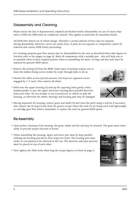
<strong>ZHM</strong> Series Installation and Operating InstructionsDisassembly and CleaningPlease ensure the line is depressurised, emptied and flushed before disassembly. In case of return shipmentto KEM the <strong>ZHM</strong> must be completely cleaned. This applies in particular for hazardous fluids.All KEM flow meters are of robust design. Therefore a certain amount of force may be requiredduring disassembly. However, never use undue force, if parts do not separate or components cannot beremoved and contact KEM before proceeding.For cleaning purposes gear flow meters may be disassembled by the user as described below (the figures inbrackets refer to the images on page 4). Mark all components with a suitable pen – this will help you tore-assemble them in their original position when re-assembling the meter. O-rings and flat seals must bereplaced by genuine KEM spares.• Remove the pickup (1) from the <strong>ZHM</strong>. Some types of pickups require you tolosen the hidden fixing screws inside the outer through holes to do so.• Slacken the Allen screws (2) and unscrew, but keep two opposed screwsengaged by 1–2 turns. Now remove all others.• Hold onto the upper housing (3) and tap the opposing bolts gently with ahammer/mallet to part the upper and lower housing (4) in parallel directionfrom each other. Do not attempt to use screwdrivers or chisels to split thehousing, as otherwise the shafts, bearings and locating pins may be damaged.• Having separated the housing, remove gears and shafts (5) and clean the parts using a solvent if necessary.Also remove the O-ring (7) and clean the groove except where flat seals (7) are being used with lightweightor cartridge gear flow meters. Remember to replace the seals by genuine KEM spares.Re-Assembly• Upon perfect cleaning of the housing, the gears, shafts and the seal may be inserted. The gears must rotateeasily to provide proper function in future.• When assembling the housing, upper and lower part must be kept parallel,utilising the locating pins (6) in their respective holes. The locating pins mustunder no circumstances be removed or left out. The material codes (see picture)must be placed on top of each other.• Now tighten the Allen bolts observing the torque figures as listed on page 6.4 KEM