p1_partA - Spatial Design@Massey
p1_partA - Spatial Design@Massey
p1_partA - Spatial Design@Massey

You also want an ePaper? Increase the reach of your titles
YUMPU automatically turns print PDFs into web optimized ePapers that Google loves.
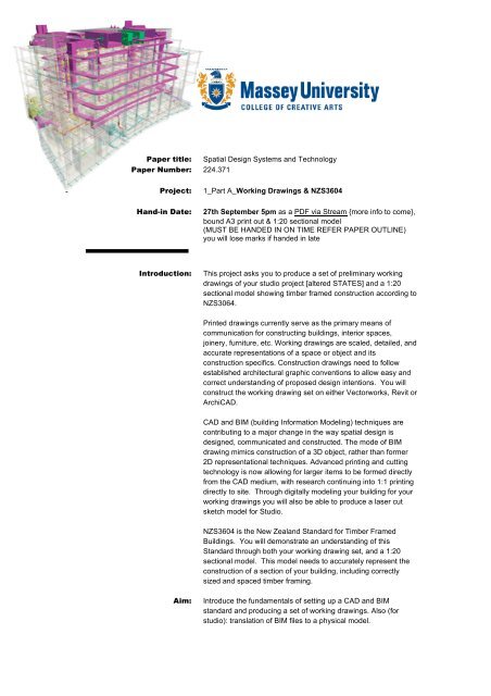
Paper title: <strong>Spatial</strong> Design Systems and TechnologyPaper Number: 224.371Project:1_Part A_Working Drawings & NZS3604Hand-in Date:27th September 5pm as a PDF via Stream {more info to come},bound A3 print out & 1:20 sectional model(MUST BE HANDED IN ON TIME REFER PAPER OUTLINE)you will lose marks if handed in lateIntroduction:This project asks you to produce a set of preliminary workingdrawings of your studio project [altered STATES] and a 1:20sectional model showing timber framed construction according toNZS3064.Printed drawings currently serve as the primary means ofcommunication for constructing buildings, interior spaces,joinery, furniture, etc. Working drawings are scaled, detailed, andaccurate representations of a space or object and itsconstruction specifics. Construction drawings need to followestablished architectural graphic conventions to allow easy andcorrect understanding of proposed design intentions. You willconstruct the working drawing set on either Vectorworks, Revit orArchiCAD.CAD and BIM (building Information Modeling) techniques arecontributing to a major change in the way spatial design isdesigned, communicated and constructed. The mode of BIMdrawing mimics construction of a 3D object, rather than former2D representational techniques. Advanced printing and cuttingtechnology is now allowing for larger items to be formed directlyfrom the CAD medium, with research continuing into 1:1 printingdirectly to site. Through digitally modeling your building for yourworking drawings you will also be able to produce a laser cutsketch model for Studio.NZS3604 is the New Zealand Standard for Timber FramedBuildings. You will demonstrate an understanding of thisStandard through both your working drawing set, and a 1:20sectional model. This model needs to accurately represent theconstruction of a section of your building, including correctlysized and spaced timber framing.Aim:Introduce the fundamentals of setting up a CAD and BIMstandard and producing a set of working drawings. Also (forstudio): translation of BIM files to a physical model.
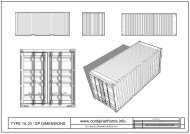
224.371_Project One_Part A_cont.Brief:This assignment is structured into 2 parts.You will start by setting up Vectorworks/Revit/ArchiCAD, usingclasses and layers (or equivalent). Then draw a 3D model ofyour proposed building, which then will be used to create theplans and sections, etc. Working drawings are often used as partof the design process, they are a great way to check designideas work/fit within the requirements of the project.The Set should contain, but is not limited to:Cover SheetSite PlanFloor PlanElevationsSectionsDetailsPart one [drawing]: Once your 3D CAD model of your building isunderway, set out each sheet with a basic layout of content.Before the mid-semester break, put together a 50% check set tobe handed in for comments and red-lining…….Part one [model] – for Studio: Once your CAD model is built,work with a copy of your digital model to prepare a file for a lasercut model. Cut and assemble model as required. Given that themodel is small scale, consider what material to edit, what tomaintain. Consider the function of the model – thecommunication of primary spatial idea/s and language. You areto decide what material(s) to use.Part two [drawing]: After the break, continue drawing andintegrate redline information once your check set is returned. Doa final check of document prior to issuing the set as a printeddocument, and digital copy.Part two [model]: Building your CAD model should have givenyou a good understanding of the building’s construction.Demonstrate this in a 1:20 scale model of a 2m deep section ofyour building. This model should be built using appropriatematerials and should show accurate timber frame construction.Project Requirements:A set of Preliminary working drawings of your studio project.A 1:20 sectional model showing construction to NZS3604.A small laser cut model to scale (for Studio).As well as a printed, bound copy of your drawings, and your 1:20model, you will provide digital copies of your drawings in thefollowing format:371_p2_lastname_firstname_dwg_07.pdf
224.371_Project One_Part A_cont.Assessment:The project will be assessed to the extent that it:• Investigates architectural graphic communication• Creatively explores digital media and its relationship totraditional architectural graphic processes• Demonstrates understanding of timber framed structure• Effectively and coherently communicates design intentand structural understanding through both drawings andmodelsFeedback will be given after completion of the project.Learning Outcomes:The student should be able to:- Confidently use computer applications introduced in thisproject- Apply computer application skills gained to inform designprocess and design presentation- Understand the requirements of working drawings- Understand and reference NZ Building StandardsProcedure and Timetable:week 1Wed. 17th Jul 10B01Project intro – basic timber framed building, drawing setsIndependent study:- have a go using VW/Revit/ArchiCAD,- choose which one you want to work on- set up file & start drawing model- lay out existing drawing set (plan, elevations)week 2Wed. 24th Jul 10B01NZS3604, timber framed building structureIndependent study:- complete NZS3604 quiz on Stream- add timber framing into your CAD model- add a section showing framing to your drawingset (consider line weights and conventions)week 3week 4week 5week 6Wed. 31st JulComplete existing drawing set for hand in by Friday 5pmWed. 7th Aug<strong>p1</strong>B – Building Code Check – introWed. 14th Augcontinue work on Building Code report & drawing set forproposed designWed. 21st Augcontinue work on Building Code report & drawing set forproposed designFriday 5pm – hand in 50% check set & report draftStudy breakweek 7week 8Wed. 11th Sep 10B011:20 sectional modelWed. 18th Sep 10B01
224.371_Project One_Part A_cont.Amend drawings from red-liningRevise BC report if necessaryweek 9Wed. 25th Sep 10B01Final check, finishing touches to report, drawings §ional modelFinal hand in 5pm Friday 27th SeptemberReferences:Recommended Reading:Allen, E. (1999). Fundamentals of building construction: Materials amd methods (3rd ed.). New York:Wiley.Ashcroft, R. (1992). Construction for interior designers (2nd ed.). London: Longman Scientific andTechnical.Bryan, T. (2005). Construction technology: Analysis and choice (1st ed.). Malden, MA: Blackwell Pub.Burden, E. E. (2005). Illustrated dictionary of building design + construction. New York: McGraw-Hill.Condor, T., & Building Research Association of New Zealand. (2000). BRANZ House Building Guide(Rev. ed., p. 250). Porirua City, N.Z: BRANZ.Ching, F. (2000). Building construction illustrated (3rd ed.). New York: John Wiley.Duncan, J. R. (2002). Innovation in the building sector: Trends and new technologies. Porirua N.Z.:BRANZ.Glossary of building terms. (1998).). Wellington N.Z.: Standards New Zealand.Kilmer, W. O. (2003). Construction drawings and details for interiors: Basic skills. New York: John Wiley& Sons.McGowan, M. (2003). Interior graphic standards. New York; Chichester: Wiley.Seeley, I. H. (1995). Building technology (5th ed.). Basingstoke: Macmillan.Stitt, F. A. (1998). Working drawing manual. New York; London: McGraw-Hill.Styles, K. (2004). Working drawings handbook (4th ed.). Boston, MA: Elsevier/Architectural Press.Wakita, O. A. (2002). The professional practice of architectural working drawings (3rd ed.). New York: J.Wiley & Sons.Websites:Vectorworks:Digital Vision:http://www.nemetschek.net/http://v3.digitalvis.com/working_drawings_gallery.php