
You also want an ePaper? Increase the reach of your titles
YUMPU automatically turns print PDFs into web optimized ePapers that Google loves.
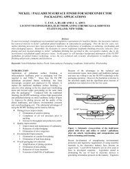
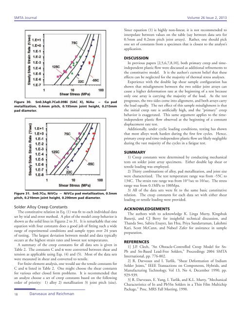
<strong>SMTA</strong> <strong>Journal</strong> Volume 26 Issue 2, 2013Since equation (1) is highly non-linear, it is not recommended tointerpolate between values on the table (say between data sets for0.5mm and 0.2mm pitch joint arrays). Rather, one should pickone set <strong>of</strong> constants from a specimen that is closest to the analyst’sapplication.Figure 30. Sn0.3Ag0.7Cu0.09Bi (SAC X), NiAu -- Cu padmetallization, 0.4mm pitch, 0.195mm joint height, 0.215mmpad diameter.Figure 31. Sn0.7Cu, NiVCu -- NiVCu pad metallization, 0.5mmpitch, 0.210mm joint height, 0.290mm pad diameter.Solder Alloy Creep ConstantsThe constitutive relation in Eq. (1) was fit to each individual dataset by trial and error method. A plot <strong>of</strong> the model creep behavior isshown as the solid lines in Figures 2 to 31. It is remarkable that oneequation with four constants does a good job <strong>of</strong> fitting such a widerange <strong>of</strong> experimental conditions and sample types over 24 years<strong>of</strong> testing. The largest deviation between model and data typicallyoccurs at the highest strain rates and lowest test temperatures.A summary <strong>of</strong> the creep constants for all data sets is given inTable 2. The constants C and α were converted between shear andtension as applicable using Eqs. (4) and (5). Most <strong>of</strong> the data setswere measured in shear and converted to tensile.For finite element analysis, one would use the tensile constants forC and α listed in Table 2. One might choose the shear constantsfor various other closed form problems. It is recommended thatan analyst choose a set <strong>of</strong> creep constants based on the followingorder <strong>of</strong> priority: 1) alloy 2) metallization 3) joint pitch (size).18Darveaux and ReichmanDISCUSSIONIn previous papers [2,5,6,7,8,10], both primary creep and timeindependentplastic flow were discussed as additional refinements tothe constitutive model. It is the author’s current belief that theseeffects can be neglected for the majority <strong>of</strong> thermal stress analyses.Experience with the double lap shear sample configuration hasshown that misalignment between the two solder joint arrays cancause a higher deformation rate at the beginning <strong>of</strong> a test becauseonly one array is carrying the majority <strong>of</strong> the load. As the testprogresses, the two sides come into alignment, and both arrays carrythe load equally. The net effect <strong>of</strong> this sample misalighment is thatthe initial creep rate is artificially high, and the “primary” creepbehavior is exaggerated. This same argument applies to the timeindependentplastic flow observed at the beginning <strong>of</strong> a constantdisplacement rate test.Additionally, under cyclic loading conditions, testing has shownthat most alloys work harden during the first few cycles. Hence,primary creep and time-independent plastic flow are likely negligibleduring the vast majority <strong>of</strong> the cycles in a fatigue test.SUMMARY1) Creep constants were determined by conducting mechanicaltests on solder joint array specimens. Either double lap shear ortensile loading was employed.2) Thirty combinations <strong>of</strong> alloy, pad metallization, and joint sizewere characterized. The test temperature range was from -55C to134C. The strain rate range was from 10 -8 /sec to 10/sec. The stressrange was from 0.1MPa to 100Mpa.3) All <strong>of</strong> the data sets were fit to the same basic constitutiverelation. The creep constants for each data set with either shearloading or tensile loading were provided.ACKNOWLEDGEMENTSThe authors wish to acknowledge K. Linga Murty, KingshukBanerji, and CJ Berry for insightful technical discussion, andThanda Swe, Sabira Enayet, Ian Hsu, Priya Sundarraman, LakshmiKari, Scott McCann, and Nabeel Zafer for assistance in samplepreparation.REFERENCES1] J.P. Clech, “An Obstacle-Controlled Creep Model for Sn-Pb and Sn-Based Lead-Free Solders,” Proceedings 2004 <strong>SMTA</strong>International, pp. 776-802.2] R. Darveaux and I. Turlik, “Shear Deformation <strong>of</strong> IndiumSolder Joints,” IEEE Transactions on Components, Hybrids, andManufacturing <strong>Technology</strong>, Vol 13, No 4, December 1990, pp.929-939.3] R. Darveaux, E. Yung, I. Turlik, and K.L. Murty, “MechanicalCharacteristics <strong>of</strong> In and Pb5Sn Solders in a Thin Film MultichipPackage,” Proc. MRS Fall Meeting, 1990.