invertec 135s, 150s & 170s - Rapid Welding and Industrial Supplies ...
invertec 135s, 150s & 170s - Rapid Welding and Industrial Supplies ...
invertec 135s, 150s & 170s - Rapid Welding and Industrial Supplies ...

You also want an ePaper? Increase the reach of your titles
YUMPU automatically turns print PDFs into web optimized ePapers that Google loves.
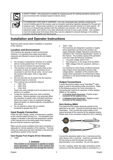
SAFETY MARK: This equipment is suitable for supplying power for welding operations carried out inan environment with increased hazard of electric shock.CYLINDER MAY EXPLODE IF DAMAGED: Use only compressed gas cylinders containing thecorrect shielding gas for the process used <strong>and</strong> properly operating regulators designed for the gas <strong>and</strong>pressure used. Always keep cylinders in an upright position securely chained to a fixed support. Donot move or transport gas cylinders with the protection cap removed. Do not allow the electrode,electrode holder, work clamp or any other electrically live part to touch a gas cylinder. Gas cylindersmust be located away from areas where they may be subjected to physical damage or the weldingprocess including sparks <strong>and</strong> heat sources.Installation <strong>and</strong> Operator InstructionsRead this entire section before installation or operationof the machine.Location <strong>and</strong> EnvironmentThis machine can operate in harsh environments.However, it is important that simple preventativemeasures are followed to assure long life <strong>and</strong> reliableoperation:Do not place or operate this machine on a surfacewith an incline greater than 15° from horizontal.Do not use this machine for pipe thawing.This machine must be located where there is freecirculation of clean air without restrictions for airmovement to <strong>and</strong> from the air vents. Do not coverthe machine with paper, cloth or rags whenswitched on.Dirt <strong>and</strong> dust that can be drawn into the machineshould be kept to a minimum.This machine has a protection rating of: 135S: IP21 150S: IP23 170S: IP23Keep it dry when possible <strong>and</strong> do not place it on wetground or in puddles.Locate the machine away from radio controlledmachinery. Normal operation may adversely affectthe operation of nearby radio controlled machinery,which may result in injury or equipment damage.Read the section on electromagnetic compatibility inthis manual.Do not operate in areas with an ambienttemperature greater than 40°C.Input Supply ConnectionCheck the input voltage, phase, <strong>and</strong> frequency suppliedto this machine before turning it on. The allowable inputvoltage is indicated in the technical specification sectionof this manual <strong>and</strong> on the rating plate of the machine.Be sure that the machine is grounded. 150S / 170S:The machines are designed to operate on enginedriven generators as long as the auxiliary cansupply adequate voltage, frequency <strong>and</strong> power asindicated in the "Technical Specification" section ofthis manual. The auxiliary supply of the generatormust also meet the following conditions: Vac peak voltage: below 410V. Vac frequency: in the range of 50 <strong>and</strong> 60Hz. RMS voltage of the AC waveform: 230Vac ±15%.It is important to check these conditions becausemany engine driven generators produce highvoltage spikes. Operation of this machine withengine driven generators not conforming to theseconditions is not recommended <strong>and</strong> may damagethe machine.Output ConnectionsA quick disconnect system using Twist-Mate TM cableplugs is used for the welding cable connections. Referto the following sections for more information onconnecting the machine for operation of stick welding(MMA) or TIG welding. (+) Positive Quick Disconnect: Positive outputconnector for the welding circuit. (-) Negative Quick Disconnect: Negative outputconnector for the welding circuit.Stick <strong>Welding</strong> (MMA)First determine the proper electrode polarity for theelectrode to be used. Consult the electrode data for thisinformation. Then connect the output cables to theoutput terminals of the machine for the selected polarity.Shown here is the connection method for DC(+) welding.Make sure the power available at the input connection isadequate for normal operation of the machine. The fuserating <strong>and</strong> cable sizes are both indicated in the technicalspecification section of this manual.Input Supply From Engine Driven Generators 135S:EnglishWARNINGThis machine is not designed to operate on enginedriven generators. Operation of this machine withengine driven generators may damage the machine.2Connect the electrode cable to the (+) terminal <strong>and</strong> thework clamp to the (-) terminal. Insert the connector withthe key lining up with the keyway <strong>and</strong> rotateapproximately ¼ turn clockwise. Do not over tighten.For DC(-) welding, switch the cable connections at themachine so that the electrode cable is connected to (-)English