201 TS Operating Manual THERMAL ARC - Victor Technologies
201 TS Operating Manual THERMAL ARC - Victor Technologies
201 TS Operating Manual THERMAL ARC - Victor Technologies

You also want an ePaper? Increase the reach of your titles
YUMPU automatically turns print PDFs into web optimized ePapers that Google loves.
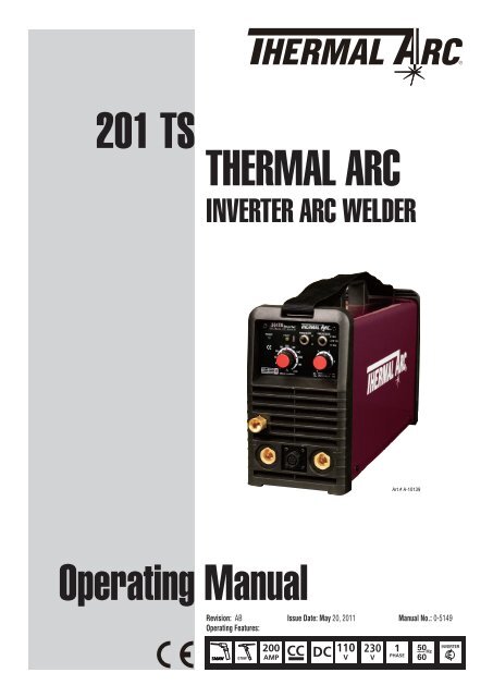
<strong>201</strong> <strong>TS</strong>tHERMAL aRCinverter <strong>ARC</strong> weldERSTICKTIGTIG/STICK32A OUTLET32A OUTLET16A OUTLETArt # A-10139<strong>Operating</strong> <strong>Manual</strong>Revision: AB Issue Date: May 20, <strong>201</strong>1 <strong>Manual</strong> No.: 0-5149<strong>Operating</strong> Features:5060 Hz
WE APPRECIATE YOUR BUSINESS!Congratulations on your new Thermal Arc product. We are proud to have you asour customer and will strive to provide you with the best service and reliabilityin the industry. This product is backed by our extensive warranty and worldwideservice network. To locate your nearest distributor or service agency call+44 (0) 1257 261 755, or visit us on the web at www.Thermalarc.com.This <strong>Operating</strong> <strong>Manual</strong> has been designed to instruct you on the correct useand operation of your Thermal Arc product. Your satisfaction with this productand its safe operation is our ultimate concern. Therefore please take the timeto read the entire manual, especially the Safety Precautions. They will help youto avoid potential hazards that may exist when working with this product. Wehave made every effort to provide you with accurate instructions, drawings,and photographs of the product(s) we used when writing this manual. Howevererrors do occur and we apologize if there are any contained in this manual.Due to our constant effort to bring you the best products, we may make animprovement that does not get reflected in the manual. If you are ever in doubtabout what you see or read in this manual with the product you received,then check for a newer version of the manual on our website or contact ourcustomer support for assistance.YOU ARE IN GOOD COMPANY!The Brand of Choice for Contractors and Fabricators Worldwide.Thermal Arc is a Global Brand of Arc Welding Products for ThermadyneIndustries Inc. We manufacture and supply to major welding industry sectorsworldwide including; Manufacturing, Construction, Mining, Automotive,Aerospace, Engineering, Rural and DIY/Hobbyist.We distinguish ourselves from our competition through market-leading,dependable products that have stood the test of time. We pride ourselves ontechnical innovation, competitive prices, excellent delivery, superior customerservice and technical support, together with excellence in sales and marketingexpertise.Above all, we are committed to develop technologically advanced products toachieve a safer working environment within the welding industry.
!WARNINGSRead and understand this entire <strong>Manual</strong> and your employer’s safety practices before installing,operating, or servicing the equipment.While the information contained in this <strong>Manual</strong> represents the Manufacturer’s best judgement,the Manufacturer assumes no liability for its use.<strong>Operating</strong> <strong>Manual</strong> Number 0-5149 for:Thermal Arc <strong>201</strong> <strong>TS</strong> Power Source Arc WelderThermal Arc <strong>201</strong> <strong>TS</strong> System with Stick/TIG Kit & CasePart Number W1003802Part Number W1003803Published by:Thermadyne Industries, Inc.82 Benning StreetWest Lebanon, New Hampshire, USA 03784(603) 298-5711www.thermadyne.comCopyright <strong>201</strong>1 byThermadyne Industries, Inc.All rights reserved.Reproduction of this work, in whole or in part, without written permission of thepublisher is prohibited.The publisher does not assume and hereby disclaims any liability to any party for anyloss or damage caused by any error or omission in this <strong>Manual</strong>, whether such errorresults from negligence, accident, or any other cause.Publication Date: April 20, <strong>201</strong>1Revision AB date: May 20, <strong>201</strong>1Record the following information for Warranty purposes:Where Purchased:_____________________________________Purchase Date:_____________________________________Equipment Serial #:_____________________________________
TABLE OF CONTEN<strong>TS</strong>SECTION 1:<strong>ARC</strong> WELDING SAFETY INSTRUCTIONS AND WARNINGS...................................... 1-11.01 Arc Welding Hazards........................................................................................ 1-11.02 Principal Safety Standards............................................................................... 1-51.03 Declaration Of Conformity............................................................................... 1-6SECTION 2:INTRODUCTION ...................................................................................... 2-12.01 How to Use This <strong>Manual</strong>.................................................................................. 2-12.02 Equipment Identification.................................................................................. 2-12.03 Receipt of Equipment....................................................................................... 2-12.04 Transportation Methods................................................................................... 2-12.05 Symbol Chart................................................................................................... 2-22.06 Description...................................................................................................... 2-32.07 User Responsibility.......................................................................................... 2-32.08 Duty Cycle........................................................................................................ 2-42.09 Specifications.................................................................................................. 2-5SECTION 3:INSTALLATION, OPERATION AND SETUP......................................................... 3-13.01 Environment.................................................................................................... 3-13.02 Location........................................................................................................... 3-13.03 Electrical Input Connections............................................................................ 3-13.04 Electromagnetic Compatibility......................................................................... 3-33.05 Setup for Welding............................................................................................ 3-43.06 STICK (MMA) Setup........................................................................................ 3-53.07 LIFT TIG / HF TIG (GTAW) Setup...................................................................... 3-73.08 Leak Testing the System.................................................................................. 3-83.09 When You Finish Using the Regulator.............................................................. 3-83.10 Storage of the Regulator.................................................................................. 3-8
TABLE OF CONTEN<strong>TS</strong>SECTION 4:OPERATION............................................................................................ 4-14.01 Front Panel...................................................................................................... 4-14.02 Welding Current Control Explanation............................................................... 4-34.03 STICK (MMA) Electrode Polarity...................................................................... 4-34.04 Effects of Stick Welding Various Materials....................................................... 4-34.05 GTAW Electrode Polarity.................................................................................. 4-44.06 Guide for Selecting Filler Wire......................................................................... 4-44.07 Tungsten Electrode Current Ranges................................................................. 4-44.08 Shielding Gas Selection................................................................................... 4-44.09 Tungsten Electrode Types................................................................................ 4-54.10 TIG Welding Parameters for Steel.................................................................... 4-54.11 Arc Welding Practice........................................................................................ 4-54.12 Welding Position.............................................................................................. 4-64.13 Joint Preparations............................................................................................ 4-74.14 Arc Welding Technique.................................................................................... 4-84.15 The Welder....................................................................................................... 4-84.16 Striking the Arc................................................................................................ 4-84.17 Arc Length....................................................................................................... 4-84.18 Rate of Travel................................................................................................... 4-84.19 Making Welded Joints...................................................................................... 4-94.20 Distortion....................................................................................................... 4-114.21 The Cause of Distortion................................................................................. 4-114.22 Overcoming Distortion Effects....................................................................... 4-12SECTION 5:SERVICE................................................................................................ 5-15.01 Maintenance and Inspection............................................................................ 5-15.02 STICK (MMA) Welding Problems .................................................................... 5-25.03 TIG Welding Problems .................................................................................... 5-35.04 Power Source Problems ................................................................................. 5-4APPENDIX 1: OPTIONS AND ACCESSORIES............................................................. A-1APPENDIX 2: REPLACEMENT PAR<strong>TS</strong>..................................................................... A-2APPENDIX 3: <strong>201</strong> <strong>TS</strong> SYSTEM SCHEMATIC ............................................................. A-4LIMITED WARRANTY & WARRANTY SCHEDULE
TABLE OF CONTEN<strong>TS</strong>Thermal Arc <strong>201</strong> <strong>TS</strong> Stick/TIG SystemPart Number W1003803• Thermal Arc <strong>201</strong> <strong>TS</strong> power supply in toolbox• 26 TIG torch, 3.8m (12.5ft) with Integrated Controls & accessory Kit• Electrode holder, 5m (16.4ft)• Work lead, 5m (16.4ft)• 4 GP 3.2mm (1/8") dia stick electrodes• Thermal Arc <strong>201</strong> <strong>TS</strong> Gas Hose lead 4m (13ft)• <strong>Operating</strong> manualArt # A-10140
<strong>THERMAL</strong> <strong>ARC</strong> <strong>201</strong> <strong>TS</strong>SAFE INSTRUCTIONSECTION 1:<strong>ARC</strong> WELDING SAFETY INSTRUCTIONS AND WARNINGS!WARNINGPROTECT YOURSELF AND OTHERS FROM POSSIBLE SERIOUS INJURY OR DEATH. KEEP CHILDRENAWAY. PACEMAKER WEARERS KEEP AWAY UNTIL CONSULTING YOUR DOCTOR. DO NOT LOSE THESEINSTRUCTIONS. READ OPERATING/INSTRUCTION MANUAL BEFORE INSTALLING, OPERATING ORSERVICING THIS EQUIPMENT.Welding products and welding processes can cause serious injury or death, or damage to other equipment orproperty, if the operator does not strictly observe all safety rules and take precautionary actions.Safe practices have developed from past experience in the use of welding and cutting. These practices must belearned through study and training before using this equipment. Some of these practices apply to equipmentconnected to power lines; other practices apply to engine driven equipment. Anyone not having extensivetraining in welding and cutting practices should not attempt to weld.Safe practices are outlined in the European Standard EN60974-1 entitled: Safety in welding and allied processesPart 2: Electrical. This publication and other guides to what you should learn before operating this equipmentare listed at the end of these safety precautions. HAVE ALL INSTALLATION, OPERATION, MAINTENANCE,AND REPAIR WORK PERFORMED ONLY BY QUALIFIED PEOPLE.1.01 Arc Welding HazardsWARNINGELECTRIC SHOCK can kill.Touching live electrical parts can causefatal shocks or severe burns. The electrodeand work circuit is electrically live wheneverthe output is on. The input power circuitand machine internal circuits are alsolive when power is on. In semiautomaticor automatic wire welding, the wire, wirereel, drive roll housing, and all metal partstouching the welding wire are electricallylive. Incorrectly installed or improperlygrounded equipment is a hazard.1. Do not touch live electrical parts.2. Wear dry, hole-free insulating gloves and bodyprotection.3. Insulate yourself from work and ground using dryinsulating mats or covers.4. Disconnect input power or stop engine beforeinstalling or servicing this equipment. Lock inputpower disconnect switch open, or remove linefuses so power cannot be turned on accidentally.5. Properly install and ground this equipment accordingto its Owner’s <strong>Manual</strong> and national, state, andlocal codes.6. Turn off all equipment when not in use. Disconnectpower to equipment if it will be left unattended orout of service.7. Use fully insulated electrode holders. Never dipholder in water to cool it or lay it down on theground or the work surface. Do not touch holdersconnected to two welding machines at the sametime or touch other people with the holder orelectrode.8. Do not use worn, damaged, undersized, or poorlyspliced cables.9. Do not wrap cables around your body.10. Ground the workpiece to a good electrical (earth)ground.11. Do not touch electrode while in contact with thework (ground) circuit.12. Use only well-maintained equipment. Repair orreplace damaged parts at once.13. In confined spaces or damp locations, do not use awelder with AC output unless it is equipped with avoltage reducer. Use equipment with DC output.14. Wear a safety harness to prevent falling if workingabove floor level.15. Keep all panels and covers securely in place.<strong>Manual</strong> 0-5149 1-1 General Information
SAFE INSTRUCTION<strong>THERMAL</strong> <strong>ARC</strong> <strong>201</strong> <strong>TS</strong>WARNING<strong>ARC</strong> RAYS can burn eyes and skin; NOISEcan damage hearing.Arc rays from the welding process produceintense heat and strong ultraviolet raysthat can burn eyes and skin. Noise fromsome processes can damage hearing.1. Use a Welding Helmet or Welding Faceshield fittedwith a proper shade of filter (see ANSI Z49.1 andEN 60974-1 listed in Safety Standards) to protectyour face and eyes when welding or watching.2. Wear approved safety glasses. Side shields recommended.3. Use protective screens or barriers to protect othersfrom flash and glare; warn others not to watch thearc.4. Wear protective clothing made from durable,flame-resistant material (wool and leather) andfoot protection.5. Use approved ear plugs or ear muffs if noise levelis high.6. Never wear contact lenses while welding.Welding or CuttingOperationEye protection filter shade selector for welding or cutting(goggles or helmet), from AWS A6.2-73.Electrode SizeMetal Thicknessor Welding CurrentFilterShadeNo.Torch soldering 2WARNINGFUMES AND GASES can be hazardous toyour health.Welding produces fumes and gases.Breathing these fumes and gases can behazardous to your health.1. Keep your head out of the fumes. Do not breaththe fumes.2. If inside, ventilate the area and/or use exhaust atthe arc to remove welding fumes and gases.3. If ventilation is poor, use an approved air-suppliedrespirator.4. Read the Material Safety Data Sheets (MSDSs)and the manufacturer’s instruction for metals,consumables, coatings, and cleaners.5. Work in a confined space only if it is well ventilated,or while wearing an air-supplied respirator.Shielding gases used for welding can displace aircausing injury or death. Be sure the breathing airis safe.6. Do not weld in locations near degreasing, cleaning,or spraying operations. The heat and rays of thearc can react with vapors to form highly toxic andirritating gases.Welding or CuttingOperationGas metal-arcwelding (MIG)Electrode SizeMetal Thicknessor Welding CurrentTorch brazing 3 or 4 Non-ferrous base metal All 11Oxygen Cutting Non-ferrous base metal All 12Light Under 1 in., 25 mm 3 or 4 Gas tungsten arc welding All 12Medium 1 to 6 in., 25-150 mm 4 or 5 (TIG) All 12Heavy Over 6 in., 150 mm 5 or 6 Atomic hydrogen welding All 12Gas welding Carbon arc welding All 12Light Under 1/8 in., 3 mm 4 or 5 Plasma arc weldingMedium 1/8 to 1/2 in., 3-12 mm 5 or 6 Carbon arc air gougingHeavy Over 1/2 in., 12 mm 6 or 8 Light 12Shielded metal-arcwelding(stick) electrodesFilterShadeNo.Under 5/32 in., 4 mm 10 Heavy 145/32 to 1/4 in.,4 to 6.4 mm12 Plasma arc cuttingOver 1/4 in., 6.4 mm 14 Light Under 300 Amp 9Medium 300 to 400 Amp 12Heavy Over 400 Amp 14General Information 1-2 <strong>Manual</strong> 0-5149
<strong>THERMAL</strong> <strong>ARC</strong> <strong>201</strong> <strong>TS</strong>7. Do not weld on coated metals, such as galvanized,lead, or cadmium plated steel, unless the coatingis removed from the weld area, the area is wellventilated, and if necessary, while wearing an airsuppliedrespirator. The coatings and any metalscontaining these elements can give off toxic fumesif welded.WARNINGWELDING can cause fire or explosion.Sparks and spatter fly off from the weldingarc. The flying sparks and hot metal, weldspatter, hot workpiece, and hot equipmentcan cause fires and burns. Accidental contactof electrode or welding wire to metalobjects can cause sparks, overheating,or fire.1. Protect yourself and others from flying sparks andhot metal.2. Do not weld where flying sparks can strike flammablematerial.3. Remove all flammables within 10.7 m (35 ft) of thewelding arc. If this is not possible, tightly coverthem with approved covers.4. Be alert that welding sparks and hot materials fromwelding can easily go through small cracks andopenings to adjacent areas.5. Watch for fire, and keep a fire extinguishernearby.6. Be aware that welding on a ceiling, floor, bulkhead,or partition can cause fire on the hidden side.7. Do not weld on closed containers such as tanksor drums.8. Connect work cable to the work as close to thewelding area as practical to prevent welding currentfrom traveling long, possibly unknown pathsand causing electric shock and fire hazards.9. Do not use welder to thaw frozen pipes.10. Remove stick electrode from holder or cut offwelding wire at contact tip when not in use.WARNINGFLYING SPARKS AND HOT METAL cancause injury.Chipping and grinding cause flying metal.As welds cool, they can throw off slag.SAFE INSTRUCTION1. Wear approved face shield or safety goggles. Sideshields recommended.2. Wear proper body protection to protect skin.WARNINGCYLINDERS can explode if damaged.Shielding gas cylinders contain gas underhigh pressure. If damaged, a cylinder canexplode. Since gas cylinders are normallypart of the welding process, be sure totreat them carefully.1. Protect compressed gas cylinders from excessiveheat, mechanical shocks, and arcs.2. Install and secure cylinders in an upright positionby chaining them to a stationary support or equipmentcylinder rack to prevent falling or tipping.3. Keep cylinders away from any welding or otherelectrical circuits.4. Never allow a welding electrode to touch anycylinder.5. Use only correct shielding gas cylinders, regulators,hoses, and fittings designed for the specificapplication; maintain them and associated partsin good condition.6. Turn face away from valve outlet when openingcylinder valve.7. Keep protective cap in place over valve exceptwhen cylinder is in use or connected for use.8. Read and follow instructions on compressedgas cylinders, associated equipment, and CGApublication P-1 listed in Safety Standards.!WARNINGEngines can be dangerous.WARNINGENGINE EXHAUST GASES can kill.Engines produce harmful exhaust gases.1. Use equipment outside in open, well-ventilatedareas.2. If used in a closed area, vent engine exhaust outsideand away from any building air intakes.<strong>Manual</strong> 0-5149 1-3 General Information
SAFE INSTRUCTIONWARNINGENGINE FUEL can cause fire or explosion.<strong>THERMAL</strong> <strong>ARC</strong> <strong>201</strong> <strong>TS</strong>4. Do not use welder to charge batteries or jumpstart vehicles.5. Observe correct polarity (+ and –) on batteries.Engine fuel is highly flammable.1. Stop engine before checking or adding fuel.2. Do not add fuel while smoking or if unit is nearany sparks or open flames.3. Allow engine to cool before fueling. If possible,check and add fuel to cold engine before beginningjob.4. Do not overfill tank — allow room for fuel toexpand.5. Do not spill fuel. If fuel is spilled, clean up beforestarting engine.WARNINGMOVING PAR<strong>TS</strong> can cause injury.Moving parts, such as fans, rotors, and belts can cutfingers and hands and catch loose clothing.1. Keep all doors, panels, covers, and guards closedand securely in place.2. Stop engine before installing or connecting unit.3. Have only qualified people remove guards orcovers for maintenance and troubleshooting asnecessary.4. To prevent accidental starting during servicing,disconnect negative (-) battery cable from battery.5. Keep hands, hair, loose clothing, and tools awayfrom moving parts.6. Reinstall panels or guards and close doors whenservicing is finished and before starting engine.WARNINGSPARKS can cause BATTERY GASES TOEXPLODE; BATTERY ACID can burn eyesand skin.Batteries contain acid and generate explosive gases.1. Always wear a face shield when working on a battery.WARNINGSTEAM AND PRESSURIZED HOT COOL-ANT can burn face, eyes, and skin.The coolant in the radiator can be very hotand under pressure.1. Do not remove radiator cap when engine is hot.Allow engine to cool.2. Wear gloves and put a rag over cap area whenremoving cap.3. Allow pressure to escape before completely removingcap.LEAD WARNINGThis product contains chemicals, includinglead, or otherwise produces chemicalsknown to the State of California to causecancer, birth defects and other reproductiveharm. Wash hands after handling.(California Health & Safety Code § 25249.5et seq.)WARNINGThis product, when used for welding orcutting, produces fumes or gases whichcontain chemicals know to the State ofCalifornia to cause birth defects and, insome cases, cancer. (California Health &Safety code Sec. 25249.5 et seq.)NOTEConsiderations About Welding And TheEffects of Low Frequency Electric andMagnetic FieldsThe following is a quotation from the General ConclusionsSection of the U.S. Congress, Office of Tech-2. Stop engine before disconnecting or connectingbattery cables.3. Do not allow tools to cause sparks whenworking on a battery.General Information 1-4 <strong>Manual</strong> 0-5149
<strong>THERMAL</strong> <strong>ARC</strong> <strong>201</strong> <strong>TS</strong>SAFE INSTRUCTIONnology Assessment, Biological Effects of Power Frequency Electric & Magnetic Fields - Background Paper,OTA-BP-E-63 (Washington, DC: U.S. Government Printing Office, May 1989): “...there is now a very largevolume of scientific findings based on experiments at the cellular level and from studies with animals andpeople which clearly establish that low frequency magnetic fields and interact with, and produce changes in,biological systems. While most of this work is of very high quality, the results are complex. Current scientificunderstanding does not yet allow us to interpret the evidence in a single coherent framework. Even morefrustrating, it does not yet allow us to draw definite conclusions about questions of possible risk or to offerclear science-based advice on strategies to minimize or avoid potential risks.”To reduce magnetic fields in the workplace, use the following procedures.1. Keep cables close together by twisting or taping them.2. Arrange cables to one side and away from the operator.3. Do not coil or drape cable around the body.4. Keep welding power source and cables as far away from body as practical.ABOUT PACEMAKERS:The above procedures are among those also normally recommended for pacemaker wearers.Consult your doctor for complete information.1.02 Principal Safety StandardsSafety in Welding and Cutting, ANSI Standard Z49.1, from American Welding Society, 550 N.W. LeJeune Rd.,Miami, FL 33126.Safety and Health Standards, OSHA 29 CFR 1910, from Superintendent of Documents, U.S. GovernmentPrinting Office, Washington, D.C. 20402.Recommended Safe Practices for the Preparation for Welding and Cutting of Containers That Have HeldHazardous Substances, American Welding Society Standard AWS F4.1, from American Welding Society, 550N.W. LeJeune Rd., Miami, FL 33126.National Electrical Code, NFPA Standard 70, from National Fire Protection Association, Batterymarch Park,Quincy, MA 02269.Safe Handling of Compressed Gases in Cylinders, CGA Pamphlet P-1, from Compressed Gas Association,1235 Jefferson Davis Highway, Suite 501, Arlington, VA 22202.Code for Safety in Welding and Cutting, CSA Standard W117.2, from Canadian Standards Association, StandardsSales, 178 Rexdale Boulevard, Rexdale, Ontario, Canada M9W 1R3.Safe Practices for Occupation and Educational Eye and Face Protection, ANSI Standard Z87.1, from AmericanNational Standards Institute, 1430 Broadway, New York, NY 10018.Cutting and Welding Processes, NFPA Standard 51B, from National Fire Protection Association, BatterymarchPark, Quincy, MA 02269.Safety in welding and allied processes Part 1: Fire Precautions, EN 60974-1 from SAI Global Limited, www.saiglobal.com.Safety in welding and allied processes Part 2: Electrical, EN 60974-1 from SAI Global Limited, www.saiglobal.com.Filters for eye protectors - Filters for protection against radiation generated in welding and allied operationsAS/NZS 1338.1:1992 from SAI Global Limited, www.saiglobal.com.<strong>Manual</strong> 0-5149 1-5 General Information
SAFE INSTRUCTION1.03 Declaration Of ConformityManufacturer:Address:Thermadyne Corporation82 Benning StreetWest Lebanon, New Hampshire 03784USA<strong>THERMAL</strong> <strong>ARC</strong> <strong>201</strong> <strong>TS</strong>The equipment described in this manual conforms to all applicable aspects and regulations of the ‘LowVoltage Directive’ (European Council Directive 73/23/EEC as amended by Council Directive 93/68/EEC) andto the National legislation for the enforcement of this Directive.The equipment described in this manual conforms to all applicable aspects and regulations of the “EMCDirective” (European Council Directive 89/336/EEC) and to the National legislation for the enforcement ofthis Directive.Serial numbers are unique with each individual piece of equipment and details description, parts used tomanufacture a unit and date of manufacture.National Standard and Technical SpecificationsThe product is designed and manufactured to a number of standards and technical requirements. Amongthem are:• CENELEC EN50199 EMC Product Standard for Arc Welding Equipment.• ISO/IEC 60974-1 (BS 638-PT10) (EN 60974-1) (EN50192) (EN50078) applicable to welding equipmentand associated accessories.• For environments with increased hazard of electrical shock, Power Supplies bearing the S markconform to EN50192 when used in conjunction with hand torches with exposed cutting tips, ifequipped with properly installed standoff guides.• Extensive product design verification is conducted at the manufacturing facility as part of the routinedesign and manufacturing process. This is to ensure the product is safe, when used according toinstructions in this manual and related industry standards, and performs as specified. Rigorous testingis incorporated into the manufacturing process to ensure the manufactured product meets or exceedsall design specifications.!WARNINGThis equipment does not comply with IEC 61000-3-12. If it is connected to a public low voltagesystem, it is the responsibility of the installer or user of the equipment to ensure, by consultationwith the distribution network operator if necessary, that the equipment may be connected.Thermadyne has been manufacturing products for more than 30 years, and will continue to achieveexcellence in our area of manufacture.Manufacturers responsible representative:Steve WardOperations DirectorThermadyne EuropeEuropa BuildingChorley N Industrial ParkChorley, Lancashire,England PR6 7BXGeneral Information 1-6 <strong>Manual</strong> 0-5149
INTRODUCTION2.01 How to Use This <strong>Manual</strong>This <strong>Manual</strong> usually applies to the part numbers listedon page i. To ensure safe operation, read the entiremanual, including the chapter on safety instructionsand warnings. Throughout this manual, the wordWARNING, CAUTION and NOTE may appear. Payparticular attention to the information provided underthese headings. These special annotations are easilyrecognized as follows:SECTION 2:INTRODUCTION<strong>THERMAL</strong> <strong>ARC</strong> <strong>201</strong> <strong>TS</strong>2.02 Equipment IdentificationThe unit’s identification number (specification or partnumber), model, and serial number usually appearon a nameplate attached to the machine. Equipmentwhich does not have a nameplate attached to themachine is identified only by the specification or partnumber printed on the shipping container. Recordthese numbers for future reference.2.03 Receipt of Equipment!WARNINGGives information regarding possible personalinjury. Warnings will be enclosed ina box such as this.CAUTIONRefers to possible equipment damage.Cautions will be shown in bold type.NOTEOffers helpful information concerningcertain operating procedures. Notes willbe shown in italicsYou will also notice icons from the safety section appearingthroughout the manual. These are to adviseyou of specific types of hazards or cautions relatedto the portion of information that follows. Somemay have multiple hazards that apply and would looksomething like this:When you receive the equipment, check it againstthe invoice to make sure it is complete and inspectthe equipment for possible damage due to shipping.If there is any damage, notify the carrier immediatelyto file a claim. Furnish complete information concerningdamage claims or shipping errors to the locationin your area listed in the inside back cover of thismanual. Include all equipment identification numbersas described above along with a full description ofthe parts in error.2.04 Transportation Methods!Disconnect input powerconductors from de-energized supply line beforemoving the welding power source.Lift unit with handle on top of case. Use handcart orsimilar device of adequate capacity. If using a forklift vehicle, secure the unit on a proper skid beforetransporting.<strong>Manual</strong> 0-5149 2-1 Introduction
<strong>THERMAL</strong> <strong>ARC</strong> <strong>201</strong> <strong>TS</strong>2.05 Symbol ChartINTRODUCTIONNote that only some of these symbols will appear on your model.OnSingle PhaseWire Feed FunctionOffThree PhaseWire Feed TowardsWorkpiece WithOutput Voltage Off.Dangerous VoltageThree Phase StaticFrequency Converter-Transformer-RectifierWelding GunIncrease/DecreaseRemotePurging Of GasCircuit BreakerAC Auxiliary PowerX%Duty CyclePercentageContinuous WeldModeSpot Weld ModeFusePanel/LocaltSpot TimeAmperageShielded MetalArc Welding (SMAW)t1Preflow TimeVoltageGas Metal ArcWelding (GMAW)t2Postflow TimeHertz (cycles/sec)FrequencyGas Tungsten ArcWelding (GTAW)Air Carbon ArcCutting (CAC-A)2 Step TriggerOperationPress to initiate wirefeed andwelding, release to stop.NegativePositiveConstant CurrentConstant VoltageOr Constant Potential4 Step TriggerOperationPress and hold for preflow, releaseto start arc. Press to stop arc, andhold for preflow.Direct Current (DC)High TemperaturetBurnback TimeProtective Earth(Ground)Fault IndicationDisturbance InGround SystemLineArc ForceIPMInches Per MinuteLine ConnectionTouch Start (GTAW)MPMMeters Per MinuteAuxiliary PowerVariable Inductance115V 15AReceptacle Rating-Auxiliary PowerVVoltage InputArt # A-04937Introduction 2-2 <strong>Manual</strong> 0-5149
<strong>THERMAL</strong> <strong>ARC</strong> <strong>201</strong> <strong>TS</strong>2.08 Duty CycleINTRODUCTIONThe rated duty cycle of a Welding Power Source, is a statement of the time it may be operated at its ratedwelding current output without exceeding the temperature limits of the insulation of the component parts. Toexplain the 10 minute duty cycle period the following example is used. Suppose a Welding Power Source isdesigned to operate at a 20% duty cycle, 200 amperes at 18 volts. This means that it has been designed andbuilt to provide the rated amperage (200A) for 2 minutes, i.e. arc welding time, out of every 10 minute period(20% of 10 minutes is 2 minutes). During the other 8 minutes of the 10 minute period the Welding PowerSource must idle and be allowed to cool.100110VAC INPUT9080TIG (GTAW)Duty Cycle (percentage)@40°C706050403020Safe<strong>Operating</strong>RegionStick (MMA)1000 20 40 60 80 100 120 140 160Welding Current (amps)Art # A-10141100230VAC INPUT9080Duty Cycle (percentage)@40°C706050403020Safe<strong>Operating</strong>RegionTIG (GTAW)1000 20 40 60 80 100 120 140 160 180 200Welding Current (amps)Figure 2-1: Thermal Arc <strong>201</strong> <strong>TS</strong> Duty CycleArt # A-10142Introduction 2-4 <strong>Manual</strong> 0-5149
INTRODUCTION2.09 Specifications<strong>THERMAL</strong> <strong>ARC</strong> <strong>201</strong> <strong>TS</strong>Power Source Part NumberMains PowerW1003802Nominal Supply Voltage AC 110V AC 230VNumber of Phases Single Phase Single PhaseInput Voltage Range AC 104- 127V AC 187- 253VNominal Supply Frequency 50/60 Hz 50/60 HzEffective Input Current (l1eff) 20 Amps 16 AmpsMaximum Input Current (l1 max) ∆ 39 Amps ∆ 32 AmpsSingle Phase Generator Requirements5 KVA 8 KVA[Continuous rating at nominal supply voltagewith maximum output for STICK (MMA) welding]Welding OutputWelding Current RangeStick: 10 - 125 AmpsTIG: 10 - 160 AmpsStick/TIG:10 - 200 AmpsNominal DC Open Circuit Voltage (OCV) 71V 71VWelding Output, 104º F (40º C), 10 min.(Quoted figures refer to STICK (MMA) output)125A @ 25%, 25.0V95A @ 60%, 23.8V80A @ 100%, 23.2V200A @ 20%, 28V120A @ 60%, 24.8V100A @ 100%, 24.0VRated Input Current (A) 39A 32Afor STICK (MMA) Welding Io = 125A @ 25.0V Io = 200A @ 28VRated Input Current (A) 30A 20.6Afor LIFT TIG/HF TIG (GTAW) Welding Io = 160A @ 16.4V Io = 200A @ 18VRated Output for STICK (MMA) Welding 25.0V, 125A @ 25% 28V, 200A @ 20%Rated Output for LIFT TIG/HF TIG (GTAW) 16.4V, 160A @ 30% 18V, 200A @ 25%WeldingDuty Cycle (%) 25% @ 125A 20% @ 200AWelder TypeInverter Power SourceOutput Terminal Type Heavy Duty Dinse TM 50ClassificationProtection ClassStandardsCooling MethodDimensions and WeightWelding Power Source MassWelding Power Source Dimensions (Height xWidth x Depth)IP23SEN 60974-1 EN50199Fan Cooled10 kg (22 lb.)H230mm x W135mm x D450mm( H 9.0” x W 5.3” x D 17.7”)∆ The recommended time delay fuse or circuit breaker size is 32 amp for 110V and 32 amp for 230V.<strong>Manual</strong> 0-5149 2-5 Introduction
<strong>THERMAL</strong> <strong>ARC</strong> <strong>201</strong> <strong>TS</strong>INTRODUCTIONThermal Arc continuously strives to produce the best product possible and therefore reserves the right to change, improve or revisethe specifications or design of this or any product without prior notice. Such updates or changes do not entitle the buyer of equipmentpreviously sold or shipped to the corresponding changes, updates, improvements or replacement of such items.The values specified in the table above are optimal values, your values may differ. Individual equipment maydiffer from the above specifications due to in part, but not exclusively, to any one or more of the following;variations or changes in manufactured components, installation location and conditions and local power gridsupply conditions.NOTEDue to variations that can occur in manufactured products, claimed performance, voltages, ratings,all capacities, measurements, dimensions and weights quoted are approximate only. Achievablecapacities and ratings in use and operation will depend upon correct installation, use, applications,maintenance and service.Introduction 2-6 <strong>Manual</strong> 0-5149
INSTALLATION3.01 EnvironmentSECTION 3:INSTALLATION, OPERATION AND SETUPThese units are designed for use in environmentswith increased hazard of electric shock. Examplesof environments with increased hazard of electricshock are:A. In locations in which freedom of movementis restricted, so that the operator is forcedto perform the work in a cramped (kneeling,sitting or lying) position with physical contactwith conductive parts.B. In locations which are fully or partially limitedby conductive elements, and in which there isa high risk of unavoidable or accidental contactby the operator.C. In wet or damp hot locations where humidityor perspiration considerable reduces the skinresistance of the human body and the insulationproperties of accessories.Environments with increased hazard of electric shockdo not include places where electrically conductiveparts in the near vicinity of the operator, which cancause increased hazard, have been insulated.3.02 LocationBe sure to locate the welder according to the followingguidelines:A. In areas, free from moisture and dust.B. Ambient temperature between 0° C to 40° C.C. In areas, free from oil, steam and corrosivegases.D. In areas, not subjected to abnormal vibration orshock.E. In areas, not exposed to direct sunlight or rain.F. Place at a distance of 300mm or more from wallsor similar that could restrict natural air flow forcooling.G. The enclosure design of this power sourcemeets the requirements of IP23S as outlined inEN 60529. This provides adequate protectionagainst solid objects (greater than 12mm), anddirect protection from vertical drops. Under nocircumstances should the unit be operated orconnected in a micro environment that will exceedthe stated conditions. For further informationplease refer to EN 60529.<strong>THERMAL</strong> <strong>ARC</strong> <strong>201</strong> <strong>TS</strong>H. Precautions must be taken against the powersource toppling over. The power source mustbe located on a suitable horizontal surface in theupright position when in use.!WARNINGThermal Arc advises that this equipmentbe electrically connected by a qualifiedelectrician.3.03 Electrical InputConnectionsWARNINGELECTRIC SHOCK can kill; SIGNIFICANTDC VOLTAGE is present after removal ofinput power.DO NOT TOUCH live electrical parts.SHUT DOWN welding power source, disconnect inputpower employing lockout/tagging procedures. Lockout/taggingprocedures consist of padlocking linedisconnect switch in open position, removing fusesfrom fuse box, or shutting off and red-tagging circuitbreaker or other disconnecting device.• Electrical Input RequirementsOperate the welding power source from a single-phase50/60 Hz, AC power supply. The input voltage mustmatch one of the electrical input voltages shown onthe input data label on the unit nameplate. Contact thelocal electric utility for information about the type ofelectrical service available, how proper connectionsshould be made, and inspection required. The linedisconnect switch provides a safe and convenientmeans to completely remove all electrical powerfrom the welding power supply whenever necessaryto inspect or service the unit.Do not connect an input (BROWN or BLUE) conductorto the ground terminal.Do not connect the ground (GREEN or GREEN/YELLOW) conductor to an input line terminal.Refer to Figure 3-1:1. Connect end of ground (GREEN or GREEN/YELLOW) conductor to a suitable ground. Usea grounding method that complies with allapplicable electrical codes.<strong>Manual</strong> 0-5149 3-1 Installation, Operation And Setup
<strong>THERMAL</strong> <strong>ARC</strong> <strong>201</strong> <strong>TS</strong>INSTALLATION2. Connect ends of line Active (BROWN) and Neutral (BLUE) input conductors to a suitable power suplysystem that complies with all applicable local electrical codes.3. Use Table 3-1 as a guide to select line fuses for the disconnect switch.Input Voltage110V230VCircuit Breaker or Fuse Size32A32ATable 3-1: Fuse GuideCAUTIONThe time-delay fuses or circuit breaker of an individual branch circuit may have nuisance trippingwhen welding with this product due to the amperage rating of the time-delay fuses or circuitbreaker.Welding Power SupplyArt# A-10143Primary Power CableFigure 3-1 Electrical Input ConnectionsInput PowerEach unit incorporates an INRUSH circuit. When the MAIN CIRCUIT SWITCH is turned on, the inrush circuitprovides pre-charging for the input capacitors. A relay in the Power Control Assembly (PCA) will turn onafter the input capacitors have charged to operating voltage (after approximately 5 seconds)Installation, Operation And Setup 3-2 <strong>Manual</strong> 0-5149
INSTALLATION<strong>THERMAL</strong> <strong>ARC</strong> <strong>201</strong> <strong>TS</strong>NOTEDamage to the PCA could occur if 265 VAC or higher is applied to the Primary Power Cable.ModelThermal Arc<strong>201</strong> <strong>TS</strong>Primary Supply LeadSize (Factory Fitted)H07RN-F 2.5mm²Minimum PrimaryCurrent Circuit Size(Vin/Amps)Current & Duty CycleLIFT TIG/HF TIG(GTAW)STICK (MMA)110V/39A - 125A @ 25%110V/30A 160A @ 30% -230V/32A - 200A @ 25%230V/21A 200A @ 25% -Table 3-2: Primary Circuit Sizes to Achieve Maximum Current3.04 Electromagnetic CompatibilityWARNINGExtra precautions for Electromagnetic Compatibility may be required when this Welding PowerSource is used in a domestic situation.A. Installation and Use - Users ResponsibilityThe user is responsible for installing and using the welding equipment according to the manufacturer’sinstructions. If electromagnetic disturbances are detected then it shall be the responsibility of the user ofthe welding equipment to resolve the situation with the technical assistance of the manufacturer. In somecases this remedial action may be as simple as earthing the welding circuit, see NOTE below. In other casesit could involve constructing an electromagnetic screen enclosing the Welding Power Source and the work,complete with associated input filters. In all cases, electromagnetic disturbances shall be reduced to thepoint where they are no longer troublesome.NOTEThe welding circuit may or may nor be earthed for safety reasons. Changing the earthingarrangements should only be authorised by a person who is competent to assess whether thechanges will increase the risk of injury, e.g. by allowing parallel welding current return paths whichmay damage the earth circuits of other equipment. Further guidance is given in IEC 60974-13 ArcWelding Equipment - Installation and use (under preparation).B. Assessment of AreaBefore installing welding equipment, the user shall make an assessment of potential electromagneticproblems in the surrounding area. The following shall be taken into account1. Other supply cables, control cables, signalling and telephone cables; above, below and adjacent to thewelding equipment.2. Radio and television transmitters and receivers.3. Computer and other control equipment.4. Safety critical equipment, e.g. guarding of industrial equipment.5. The health of people around, e.g. the use of pacemakers and hearing aids.6. Equipment used for calibration and measurement.7. The time of day that welding or other activities are to be carried out.8. The immunity of other equipment in the environment: the user shall ensure that other equipment beingused in the environment is compatible: this may require additional protection measures.<strong>Manual</strong> 0-5149 3-3 Installation, Operation And Setup
<strong>THERMAL</strong> <strong>ARC</strong> <strong>201</strong> <strong>TS</strong>INSTALLATIONThe size of the surrounding area to be considered will depend on the structure of the building and otheractivities that are taking place. The surrounding area may extend beyond the boundaries of the premises.C. Methods of Reducing Electromagnetic Emissions1. Mains SupplyWelding equipment should be connected to the mains supply according to the manufacturer’srecommendations. If interference occurs, it may be necessary to take additional precautions such asfiltering of the mains supply. Consideration should be given to shielding the supply cable of permanentlyinstalled welding equipment in metallic conduit or equivalent. Shielding should be electrically continuousthroughout it’s length. The shielding should be connected to the Welding Power Source so that goodelectrical contact is maintained between the conduit and the Welding Power Source enclosure.2. Maintenance of Welding EquipmentThe welding equipment should be routinely maintained according to the manufacturer’s recommendations.All access and service doors and covers should be closed and properly fastened when the weldingequipment is in operation. The welding equipment should not be modified in any way except for thosechanges and adjustments covered in the manufacturer’s instructions. In particular, the spark gaps ofarc striking and stabilising devices should be adjusted and maintained according to the manufacturer’srecommendations.3. Welding CablesThe welding cables should be kept as short as possible and should be positioned close together, runningat or close to the floor level.4. Equipotential BondingBonding of all metallic components in the welding installation and adjacent to it should be considered.However. Metallic components bonded to the work piece will increase the risk that the operator couldreceive a shock by touching the metallic components and the electrode at the same time. The operatorshould be insulated from all such bonded metallic components.5. Earthing of the WorkpieceWhere the workpiece is not bonded to earth for electrical safety, nor connected to earth because of it’ssize and position, e.g. ship’s hull or building steelwork, a connection bonding the workpiece to earthmay reduce emissions in some, but not all instances. Care should be taken to prevent the earthing ofthe workpiece increasing the risk of injury to users, or damage to other electrical equipment. Wherenecessary, the connection of the workpiece to earth should be made by direct connection to theworkpiece, but in some countries where direct connection is not permitted, the bonding should beachieved by suitable capacitance, selected according to national regulations.6. Screening and ShieldingSelective screening and shielding of other cables and equipment in the surrounding area may alleviateproblems of interference. Screening the entire welding installation may be considered for specialapplications.3.05 Setup for WeldingNOTEConventional operating procedures apply when using the Welding Power Source, i.e. connectwork lead directly to work piece and electrode lead is used to hold electrode. Wide safety marginsprovided by the design ensure that the Welding Power Source will withstand short-term overloadwithout adverse effects. The welding current range values should be used as a guide only. Currentdelivered to the arc is dependent on the welding arc voltage, and as welding arc voltage variesbetween different classes of electrodes, welding current at any one setting would vary according tothe type of electrode in use. The operator should use the welding current range values as a guidethen fine tune the welding current to suit the application.Installation, Operation And Setup 3-4 <strong>Manual</strong> 0-5149
INSTALLATION<strong>THERMAL</strong> <strong>ARC</strong> <strong>201</strong> <strong>TS</strong>WARNINGBefore connecting the work clamp to the work and inserting the electrode in the electrode holdermake sure the Primary power supply is switched off.CAUTIONRemove any packaging material prior to use. Do not block the air vents at the front or rear of theWelding Power Source.3.06 STICK (MMA) SetupSet Welding Currentas specified by theElectrode Manufacturer.Negative OutputTerminal(Dinse 50)Set Process SelectionSwitch to STICK.Set <strong>ARC</strong> ForcePositive OutputTerminal(Dinse 50)200AFigure 3-2 Setup for STICK (MMA) WeldingArt#: A-09784<strong>Manual</strong> 0-5149 3-5 Installation, Operation And Setup
<strong>THERMAL</strong> <strong>ARC</strong> <strong>201</strong> <strong>TS</strong>STICK (MMA) Mode Sequence of OperationINSTALLATIONCAUTIONBefore any welding is to begin, be sure to wear all appropriate and recommended safety equipment.1. Switch the ON/OFF Switch (located on the rear panel) to OFF.2. Connect the ground (work) clamp cable to the negative output terminal, and the electrode holder cable tothe positive output terminal. It is essential that the male plug is inserted and turned fully clockwise untilconnector locks in place to achieve reliable electrical connection.NOTEThis set up is known as DC Electrode Positive or reverse polarity. Please consult with the stick electrode manufacturerfor specific polarity recommendations.3. Connect the ground (work) clamp to your workpiece.4. Plug the power cable into the appropriate outlet, and turn the switch to the “ON” position. The power L.E.Dlight should illuminate.5. Set the “Process Selection Switch” to STICK.6. Set the weld current control knob to the desired amperage.7. Set the <strong>ARC</strong> FORCE control knob to 2.Minimum (0) provides a soft arc, low spatter & low penetration.Medium (2) provides a normal arc, improved fusion & normal penetration.Maximum (10) provides a hard arc & deep penetration.8. Install a stick electrode in the electrode holder.9. You are now ready to begin STICK WeldingNOTEGently strike the electrode on the work piece to generate a welding arc, and slowly move along the work piece whileholding a consistent arc length above base metal.Installation, Operation And Setup 3-6 <strong>Manual</strong> 0-5149
INSTALLATION3.07 LIFT TIG / HF TIG (GTAW) Setup<strong>THERMAL</strong> <strong>ARC</strong> <strong>201</strong> <strong>TS</strong>Set Process SelectionSwitch to LIFT TIG or HF TIG.Switch to 2T/4<strong>TS</strong>et Welding Currentas specified by theElectrode Manufacturer.Set DOWN SlopeSecure the gas cylinder in anupright position by chaining itto a stationary support to preventfalling or tipping.NegativeOutputTerminal(Dinse 50)Positive OutputTerminal(Dinse 50)Art # A-10100_ABLIFT TIG / HF TIG (GTAW) Sequence of OperationFigure 3-3: Setup for LIFT TIG / HF TIG (GTAW) WeldingCAUTIONBefore any welding is to begin, be sure to wear all appropriate and recommended safety equipment.1. Switch the ON/OFF Switch (located on the rear panel) to OFF.2. Connect the ground (work) clamp cable to positive output terminal. It is essential that the male plug isinserted and turned fully clockwise until connector locks in place to achieve reliable electrical connection.3. Connect the TIG torch as follows:a) Place the power cable into the negative output terminal. It is essential that the male plug is insertedand turned fully clockwise until connector locks in place to achieve reliable electrical connection;b) Place the 8 pin plug into the 8 pin socket. To make connections, align keyway, insert plug, and rotatethreaded collar fully clockwise.c) Place the TIG torch gas hose to the gas outlet and tighten with a wrench. Caution: DO NOT over tighten.4. Using a secured Argon cylinder, slowly crack open then close the cylinder valve while standing off to theside of the valve. This will remove any debris that may be around the valve & regulator seat area.5. Install the regulator (for details of VICTOR regulator, please refer to 3.08 ) and tighten with a wrench.6. Connect one end of the supplied gas hose to the outlet of the Argon regulator and tighten with a wrench.Caution: DO NOT over tighten.<strong>Manual</strong> 0-5149 3-7 Installation, Operation And Setup
<strong>THERMAL</strong> <strong>ARC</strong> <strong>201</strong> <strong>TS</strong>7. Connect the other end of the supplied gas hose tothe gas inlet fitting on the rear panel of the welderand tighten with a wrench. Caution: DO NOT overtighten.8. Open the Argon Cylinder Valve to the fully openposition.9. Connect the ground (work) clamp to your workpiece.10. Set the DOWN SLOPE control knob to the desireweld current ramp down time. Refer to Section4.01.11. Set the weld current control knob to the desiredamperage.12. The tungsten must be ground to a blunt pointin order to achieve optimum welding results. Itis critical to grind the tungsten electrode in thedirection the grinding wheel is turning.13. Install the tungsten with approximately 1/8” to ¼”sticking out from the gas cup, ensuring you havecorrect sized collet.14. Tighten the back cap then open the valve on thetorch.15. Plug the power cable into the appropriate outlet,and turn the switch to the “ON” position. Thepower L.E.D. light should illuminate. Set the“Process Selection Switch” to LIFT TIG and HFTIG16. You are now ready to begin TIG Welding.3.08 Leak Testing the SystemLeak test the system before putting into operation.1. Be sure that there is a valve in the downstreamequipment to turn off the gas flow.2. With the cylinder valve open, adjust theregulator to deliver the maximum requireddelivery pressure.3. Close the cylinder valve.4. Turn the adjusting screw/knob counterclockwiseone turn.a) If the high-pressure gauge reading drops,there is a leak in the cylinder valve, inletfitting, or high-pressure gauge.b) If the low-pressure gauge drops, there is aleak in the down stream equipment, hose,hose fitting, outlet fitting or low-pressureINSTALLATIONgauge. Check for leaks using an approvedleak detector solution.c) If the high-pressure gauge drops and thelow-pressure gauge increases at the sametime, there is a leak in the regulator seat.d) If the regulator requires service or repair,take it to a qualified repair technician.5. Once leak testing has been performed andthere are no leaks in the system, slowly openthe cylinder valve and proceed.!WARNINGIf a leak has been detected anywhere inthe system, dis continue use and havethe system repaired. DO NOT use leakingequipment. Do not attempt to repair aleaking system while the system is underpressure.3.09 When You Finish Using theRegulator1. Close the cylinder valve.2. Open the valve on the downstream equipment.This drains all pressure from the system.3. Close the valve on the downstreamequipment.4. Turn the adjusting screw counterclockwise torelease the ten sion on the adjusting spring.5. Check the gauges after a few minutes forverification that the cylinder valve is closedcompletely.3.10 Storage of the RegulatorWhen the regulator is not in use and has beenremoved from the cylinder, it should be stored in anarea where it will be pro tected from dust, oil, andgrease. The inlet and outlet should be capped toprotect against internal contamination and preventinsects from nesting.Installation, Operation And Setup 3-8 <strong>Manual</strong> 0-5149
OPERATION<strong>THERMAL</strong> <strong>ARC</strong> <strong>201</strong> <strong>TS</strong>SECTION 4:OPERATIONConventional operating procedures apply when using the Welding Power Source, i.e. connect work lead directlyto work piece and electrode lead is used to hold the electrode. The welding current range values should be usedas a guide only. Current delivered to the arc is dependent on the welding arc voltage, and as welding arc voltagevaries between different classes of electrode, welding current at any one setting would vary according to the typeof electrode in use. The operator should use the welding current range values as a guide then fine tune the weldingcurrent to suit the specific application. Refer to the electrode manufacture's literature for further information.4.01 Front PanelFront PanelThe welding power source is protected by a self re-setting thermostat. The indicator will illuminate if the dutycycle of the power source has been exceeded. If the FAULT light illuminates wait for the FAULT light to extinguishbefore resuming welding.(C) Trigger Mode Selection Switch(A) Power On Indicator(D) Process Selection Switch(B) Fault Indicator(F) Arc Force/DownSlope Control(E) Welding CurrentControlSTICK 32AOUTLETTIG 32AOUTLET TIG/STICK 16AOUTLET (G) Gas Outlet(I) 8 Pin Control SocketNegative Output TerminalPositive Output TerminalArt # A-10146Figure 4-1: Thermal Arc <strong>201</strong> <strong>TS</strong> ControlsA. POWER IndicatorThe POWER Indicator illuminates when the ON/OFF switch is in the ON position and the correct mains voltage ispresent.B. FAULT IndicatorIf Fault indicator lights up continuously then that is an Overcurrent Condition and needs to be serviced by anAuthorized Thermalarc Technician.<strong>Manual</strong> 0-5149 4-1 Operation
<strong>THERMAL</strong> <strong>ARC</strong> <strong>201</strong> TsC. TRIGGER Mode Switch (LIFT TIG Mode Only)2T (Normal) ModePress the TIG Torch Trigger Switch or Foot Control andhold depressed to weld. Release the TIG Torch TriggerSwitch or Foot Control to stop welding. Down Slopeoperates in LIFT TIG (GTAW) mode only. While weldingif the TIG Torch Trigger Switch is released, the weldingcurrent ramps down to zero current over a definedperiod of time. The time period is determined by theDown Slope Control Knob (F).4T (Latch) ModeThis mode of welding is mainly used for long weld runs.The operator need only to press the TIG Torch TriggerSwitch to activate and then release the TIG Torch TriggerSwitch to continue to weld, then press the TIG TorchTrigger Switch again and release the TIG Torch TriggerSwitch to stop welding. This eliminates the need for theoperator to depress the TIG Torch Trigger Switch for thecomplete length of the weld. The 4T mode incorporatesa current slope function which includes a fixed currentup slope of 1 second and an adjustable current downslope. Current slope operates in TIG Mode only. Up slopeis not adjustable and activates automatically in 4T modewhen the TIG torch trigger is depressed. To activatethe Down Slope function in 4T mode while welding,the TIG Torch Trigger Switch must be depressed andheld while welding which will ramp the Welding Currentdown to zero over a defined period of time. The timeperiod is determined by the Down Slope Control Knob(F). At any time while welding if the TIG Torch TriggerSwitch is depressed and released the arc will extinguishimmediately.D. Process Selection SwitchSwitches between STICK (MMA), LIFT TIG (GTAW) andHF TIG (GTAW) modes. Refer to Section 3.06 Setupfor STICK (MMA) Welding and 3.07 Setup for TIG / HFTIG Welding.E. Welding Current ControlThe welding current is increased by turning the WeldCurrent Control Knob clockwise or decreased by turningthe Weld Current Control Knob counterclockwise. Thewelding current should be set according to the specificapplication. Refer to application notes in this sectionfor further information.F. Arc Force/Down Slope ControlArc Force is effective when in STICK (MMA) Mode only.Arc Force control provides an adjustable amount of ArcForce (or “dig”) control. This feature can be particularlybeneficial in providing the operator the ability to compensatefor variability in joint fit-up in certain situationswith particular electrodes. In general increasing the ArcForce control toward ‘10’ (maximum Arc Force) allowsOPERATIONgreater penetration control to be achieved. Down Slopeoperates in TIG mode only. It is used to set the time forweld current to ramp down. Refer to Item C (TriggerMode Selection Switch) for further information regardingDownslope operation.G. Gas OutletThe Gas Outlet is a 5/8”-18 UNF female gas fitting andis utilized for the connection of a suitable TIG Torch.H. Post Gas Flow (weld current dependant)Post Gas Flow is the time Gas flows after the arc hasextinguished. The gas flow time is proportional to weldcurrent. This is used to cool and reduce oxidization ofthe Tungsten Electrode. For example if the Welding Currentis set to 10 amps the Post Gas Flow time will beapproximately 3 seconds. For a Welding Current set to160 Amps the Post Gas Flow time will be approximately10 seconds. The Post Gas Flow time cannot be adjustedindependently of the Welding Current.I. 8 Pin Remote SocketThe 8 pin remote socket is used to connect the TIGTorch Trigger Switch to the welding Power Source. Tomake connections, align keyway, insert plug, and rotatethreaded collar fully clockwise.12345 6785k OhmsArt # A-09815_AB2 15 4 38 7 6Front View of 8 Pin SocketPlug PinFunction12 Torch Switch Input (24V) to energizeweld current. (connect pin 2&3 to turn onwelding current)3 Torch Switch Input (0V) to energize weldcurrent. (connect pin 2&3 to turn onwelding current)45 5k ohm (maximum) connection to 5k ohmremote control potentiometer6 Zero ohm (minimum) connection to 5kohm remote control potentiometer7 Wiper arm connection to 5k ohm remotecontrol potentiometer8NOTERemote Welding Current Control is not available onthis model.Operation 4-2 <strong>Manual</strong> 0-5149
OPERATIONJ. ON/OFF Switch (located on rear panel not shown)This switch controls the Mains Supply Voltage to thePower Source.4.02 Welding Current ControlExplanation32 Amp OutletThe mains power 32 Amp circuit breaker or fuse shouldnot trip at this Weld Current value when STICK welding.The environmental conditions that may cause the mainspower 32 Amp circuit breaker or fuse to trip are:a) High ambient temperatureb) Worn parts in circuit breakerc) Using an extension cabled) Low line mains power voltageOutput Scale for 110VThe inside number scale identifies the availableoutput weld current for STICK or LIFT TIG weld modes.STICK Mode: Identifies the STICK weld point for32 Amp outlet.Exceeding these points will cause nuisancetripping of the circuit breaker orfuse.Nuisance tripping should not occur on a 16 Amp outlet.Output Scale for 230VThe outside number scale identifies the available outputweld current for STICK or LIFT TIG/HF TIG weldmodes.Nuisance tripping should not occur on a 32A 230V outletfor both STICK & LIFT TIG/HF TIG Modes.STICK 32AOUTLETTIG 32AOUTLET TIG/STICK 16AOUTLET 32 Amp OutletOutput Scale for 110VOutput Scale for 230VArt # A-10147Figure 4-2: Current Control<strong>THERMAL</strong> <strong>ARC</strong> <strong>201</strong> <strong>TS</strong>4.03 STICK (MMA) Electrode PolarityStick electrodes are generally connected to the "+" PositiveOutput Terminal and the work lead to the "−" NegativeOutput Terminal but if in doubt consult the electrodemanufacturers literature for further information.4.04 Effects of Stick Welding VariousMaterialsHigh Tensile and Alloy SteelsThe two most prominent effects of welding these steelsare the formation of a hardened zone in the weld area,and, if suitable precautions are not taken, the occurrencein this zone of under-bead cracks. Hardened zone andunder-bead cracks in the weld area may be reduced byusing the correct electrodes, preheating, using highercurrent settings, using larger electrodes sizes, shortruns for larger electrode deposits or tempering in afurnace.Manganese SteelsThe effect on manganese steel of slow cooling fromhigh temperatures is to embrittle it. For this reason itis absolutely essential to keep manganese steel coolduring welding by quenching after each weld or skipwelding to distribute the heat.Cast IronMost types of cast iron, except white iron, are weldable.White iron, because of its extreme brittleness, generallycracks when attempts are made to weld it. Troublemay also be experienced when welding white-heartmalleable, due to the porosity caused by gas held inthis type of iron.Copper and AlloysThe most important factor is the high rate of heatconductivity of copper, making pre-heating of heavysections necessary to give proper fusion of weld andbase metal.Types of ElectrodesArc Welding electrodes are classified into a number ofgroups depending on their applications. There are agreat number of electrodes used for specialized industrialpurposes which are not of particular interest for everydaygeneral work. These include some low hydrogentypes for high tensile steel, cellulose types for weldinglarge diameter pipes, etc The range of electrodes dealtwith in this publication will cover the vast majority ofapplications likely to be encountered; are all easy to use.<strong>Manual</strong> 0-5149 4-3 Operation
<strong>THERMAL</strong> <strong>ARC</strong> <strong>201</strong> TsOPERATIONMetal Being Joined Electrode CommentsMild Steel E6011 This electrode is used for all-position welding or for welding onrusty, dirty, less-than-new metal. It has a deep, penetrating arcand is often the first choice for repair or maintenance work.Mild Steel E6013 This all-position, electrode is used for welding clean, new sheetmetal. Its soft arc has minimal spatter, moderate penetration andan easy-to-clean slag.Mild Steel E7014 All positional, ease to use electrode for use on thicker steel thanE6013. Especially suitable sheet metal lap joints and fillet welds,general purpose plate welding.Mild Steel E7018 A low-hydrogen, all-position electrode used when quality is anissue or for hard-to-weld metals. It has the capability of producingmore uniform weld metal, which has better impact properties atlow temperatures.Cast Iron Eni-Cl Suitable for joining all cast irons except white cast iron.Stainless Steel E318L-16 High corrosion resistances. Ideal for dairy work etc.4.05 GTAW Electrode PolarityConnect the TIG torch to the "-" Negative Output Terminal and the work lead to the "+" Positive Output Terminal fordirect current straight polarity. Direct current straight polarity is the most widely used polarity for DC TIG welding.It allows limited wear of the electrode since 70% of the heat is concentrated at the work piece.4.06 Guide for Selecting Filler Wire4.07 Tungsten Electrode Current RangesFiller Wire Diameter DC Current (Amps)1.6mm (1/16") 20 - 902.4mm (3/32") 65 - 1153.2mm (1/8") 100 - 165Electrode Diameter DC Current1.0mm (.040”) 25 - 851.6mm (1/16”) 50 - 1602.4mm (3/32”) 135 - 2354.08 Shielding Gas SelectionAlloyCarbon SteelStainless SteelNickel AlloyCopperTitaniumShielding GasWelding ArgonWelding ArgonWelding ArgonWelding ArgonWelding ArgonOperation 4-4 <strong>Manual</strong> 0-5149
OPERATION4.08 Shielding Gas Selection<strong>THERMAL</strong> <strong>ARC</strong> <strong>201</strong> <strong>TS</strong>AlloyCarbon SteelStainless SteelNickel AlloyCopperTitaniumShielding GasWelding ArgonWelding ArgonWelding ArgonWelding ArgonWelding Argon4.09 Tungsten Electrode TypesElectrode Type(Ground Finish)Thoriated 2%Ceriated 2%Welding Application Features Color CodeDC welding of mild steel, stainless steeland copper.Excellent arc starting, long life, highcurrent carrying capacity.AC & DC welding of mild steel, stainless Longer life, more stable arc, easiersteel, copper, aluminium, magnesium and starting, wider current range,their alloys.narrower & more concentrated arc.RedGrey4.10 TIG Welding Parameters for SteelBase MetalThickness1.0mm(0.040")1.2mm(0.045")1.6mm(1/16")3.2mm(1/8")4.8mm(3/16")6.4mm(1/4")DC CurrentStainlessSteelElectrodeDiameterFiller RodDiameterArgon Gas FlowRateMild SteelJoint / Type35-45 20-30 1.0mm 1.6mm 10 CFH Butt/Corner40-50 25-35 (0.040") (1/16" ) (5 LPM) Lap/Filler45-55 30-451.0mm 1.6mm 13 CFHButt/Corner50-60 35-50 (0.040") (1/16") (6 LPM) Lap/Filler60-70 40-60 1.6mm 1.6mm 15 CFH Butt/Corner70-90 50-70 (1/16") (1/16") (7 LPM) Lap/Filler80-100 65-85 1.6mm 2.4mm 15CFH Butt/Corner90-115 90-110 (1/16") (3/32") (7 LPM) Lap/Filler115-135 100-125 2.4mm 3.2mm 21CFH Butt/Corner140-165 125-150 (3/32") (1/8") (10 LPM) Lap/Filler160-175 135-160 3.2mm 4.0mm 21CFH Butt/Corner170-200 160-180 (1/8") (5/32") (10 LPM) Lap/Filler4.11 Arc Welding PracticeThe techniques used for arc welding are almost identical regardless of what types of metals are being joined.Naturally enough, different types of electrodes would be used for different metals as described in the precedingsection.<strong>Manual</strong> 0-5149 4-5 Operation
OPERATION4.13 Joint Preparations<strong>THERMAL</strong> <strong>ARC</strong> <strong>201</strong> <strong>TS</strong>In many cases, it will be possible to weld steel sections without any special preparation. For heavier sections andfor repair work on castings, etc., it will be necessary to cut or grind an angle between the pieces being joined toensure proper penetration of the weld metal and to produce sound joints.In general, surfaces being welded should be clean and free of rust, scale, dirt, grease, etc. Slag should be removedfrom oxy-cut surfaces. Typical joint designs are shown in Figure 4-11.Open Square ButtJointGap varies from1.6mm (1/16”) to 4.8mm (3/16”)depending on plate thicknessSingle Vee Butt JointNot less than70°1.6mm (1/16” ) maxSingle Vee Butt JointNot less than45°Double Vee Butt Joint1.6mm (1/16”)Not less than70°1.6mm (1/16”) maxLap Joint1.6mm (1/16”)Fillet JointTee Joints(Fillet both sides of thejoint)Corner WeldEdge JointPlug WeldPlug WeldArt # A-07695_AEFigure 4-11: Typical joint designs for arc welding<strong>Manual</strong> 0-5149 4-7 Operation
<strong>THERMAL</strong> <strong>ARC</strong> <strong>201</strong> Ts4.14 Arc Welding TechniqueArt # A-07696OPERATIONA Word to BeginnersFor those who have not yet done any welding, thesimplest way to commence is to run beads on a pieceof scrap plate. Use mild steel plate about 6.4mm (1/4")thick and a 3.2mm (1/8") electrode. Clean any paint,loose scale or grease off the plate and set it firmly onthe work bench so that welding can be carried out inthe downhand position. Make sure that the work clampis making good electrical contact with the work, eitherdirectly or through the work table. For light gauge material,always clamp the work lead directly to the job,otherwise a poor circuit will probably result.4.15 The WelderPlace yourself in a comfortable position before beginningto weld. Get a seat of suitable height and do asmuch work as possible sitting down. Don’t hold yourbody tense. A taut attitude of mind and a tensed bodywill soon make you feel tired. Relax and you will findthat the job becomes much easier. You can add muchto your peace of mind by wearing a leather apron andgauntlets. You won’t be worrying then about being burntor sparks setting alight to your clothes.Place the work so that the direction of welding is across,rather than to or from, your body. The electrode holderlead should be clear of any obstruction so that youcan move your arm freely along as the electrode burnsdown. If the lead is slung over your shoulder, it allowsgreater freedom of movement and takes a lot of weightoff your hand. Be sure the insulation on your cable andelectrode holder is not faulty, otherwise you are riskingan electric shock.4.16 Striking the ArcPractice this on a piece of scrap plate before going onto more exacting work. You may at first experience difficultydue to the tip of the electrode “sticking” to thework piece. This is caused by making too heavy a contactwith the work and failing to withdraw the electrodequickly enough. A low amperage will accentuate it. Thisfreezing-on of the tip may be overcome by scratchingthe electrode along the plate surface in the same wayas a match is struck. As soon as the arc is established,maintain a 1.6mm (1/16") to 3.2mm (1/8") gap betweenthe burning electrode end and the parent metal. Drawthe electrode slowly along as it melts down.4.17 Arc LengthFigure 4-12: Striking an arcThe securing of an arc length necessary to produce aneat weld soon becomes almost automatic. You will findthat arc produces a crackling or spluttering noise andthe weld metal comes across in large, irregular blobs.The weld bead is flattened and spatter increases. A shortarc is essential if a high quality weld is to be obtainedalthough if it is too short there is the danger of it beingblanketed by slag and the electrode tip being solidifiedin. If this should happen, give the electrode a quick twistback over the weld to detach it. Contact or “touch-weld”electrodes such as E7014 electrode do not stick in thisway, and make welding much easier.4.18 Rate of TravelAfter the arc is struck, your next concern is to maintainit, and this requires moving the electrode tip towardsthe molten pool at the same rate as it is melting away.At the same time, the electrode has to move along theplate to form a bead. The electrode is directed at theweld pool at about 20° from the vertical. The rate oftravel has to be adjusted so that a well-formed beadis produced.If the travel is too fast, the bead will be narrow andstrung out and may even be broken up into individualglobules. If the travel is too slow, the weld metal pilesup and the bead will be too large.Another difficulty you may meet is the tendency, afterthe arc is struck, to withdraw the electrode so far thatthe arc is broken again. A little practice will soon remedyboth of these faults.Operation 4-8 <strong>Manual</strong> 0-5149
OPERATION4.19 Making Welded JointsHaving attained some skill in the handling of an electrode,you will be ready to go on to make up weldedjoints.A. Butt WeldsSet up two plates with their edges parallel, as shown inFigure 4-12, allowing 1.6mm (1/16") to 2.4mm (3/32")gap between them and tack weld at both ends. This isto prevent contraction stresses from the cooling weldmetal pulling the plates out of alignment. Plates thickerthan 6.4mm (1/4") should have their mating edges beveledto form a 70° to 90° included angle. This allowsfull penetration of the weld metal to the root. Using a3.2mm (1/8") E7014 electrode at 120 amps, deposit arun of weld metal on the bottom of the joint.Do not weave the electrode, but maintain a steady rate oftravel along the joint sufficient to produce a well-formedbead. At first you may notice a tendency for undercutto form, but keeping the arc length short, the angle ofthe electrode at about 20° from vertical, and the rate oftravel not too fast, will help eliminate this. The electrodeneeds to be moved along fast enough to prevent the slagpool from getting ahead of the arc. To complete the jointin thin plate, turn the job over, clean the slag out of theback and deposit a similar weld.Figure 4-13: Butt weldArt # A-07697<strong>THERMAL</strong> <strong>ARC</strong> <strong>201</strong> <strong>TS</strong>Heavy plate will require several runs to complete thejoint. After completing the first run, chip the slag outand clean the weld with a wire brush. It is importantto do this to prevent slag being trapped by the secondrun. Subsequent runs are then deposited using eithera weave technique or single beads laid down in thesequence shown in Figure 4-13. The width of weaveshould not be more than three times the core wirediameter of the electrode. When the joint is completelyfilled, the back is either machined, ground or gougedout to remove slag which may be trapped in the root,and to prepare a suitable joint for depositing the backingrun. If a backing bar is used, it is not usually necessaryto remove this, since it serves a similar purpose to thebacking run in securing proper fusion at the root ofthe weld.B. Fillet WeldsThese are welds of approximately triangular cross-sectionmade by depositing metal in the corner of two facesmeeting at right angles. Refer to Figure 4-5.A piece of angle iron is a suitable specimen with whichto begin, or two lengths of strip steel may be tackedtogether at right angles. Using a 3.2mm (1/8") E7014electrode at 120 amps, position angle iron with oneleg horizontal and the other vertical. This is known asa horizontal-vertical (HV) fillet. Strike the arc and immediatelybring the electrode to a position perpendicularto the line of the fillet and about 45° from the vertical.Some electrodes require to be sloped about 20° awayfrom the perpendicular position to prevent slag fromrunning ahead of the weld. Refer to Figure 4-14. Do notattempt to build up much larger than 6.4mm (1/4") widthwith a 3.2mm (1/8") electrode, otherwise the weld metaltends to sag towards the base, and undercut forms onthe vertical leg. Multi-runs can be made as shown inFigure 4-15. Weaving in HV fillet welds is undesirable.Art # A-07698Figure 4-14: Weld build up sequenceArt # A-07699Figure 4-15: Electrode position for HV fillet weld<strong>Manual</strong> 0-5149 4-9 Operation
<strong>THERMAL</strong> <strong>ARC</strong> <strong>201</strong> TsOPERATIONArt # A-07700Art # A-07702Figure 4-16: Multi-runs in HV fillet weldC. Vertical Welds1. Vertical UpTack weld a three feet length of angle iron to yourwork bench in an upright position. Use a 3.2mm(1/8") E7014 electrode and set the current at 120amps. Make yourself comfortable on a seat infront of the job and strike the arc in the cornerof the fillet. The electrode needs to be about 10°from the horizontal to enable a good bead to bedeposited. Refer Figure 4-16. Use a short arc,and do not attempt to weave on the first run.When the first run has been completed de-slagthe weld deposit and begin the second run atthe bottom. This time a slight weaving motionis necessary to cover the first run and obtaingood fusion at the edges. At the completion ofeach side motion, pause for a moment to allowweld metal to build up at the edges, otherwiseundercut will form and too much metal willaccumulate in the centre of the weld. Figure4-17 illustrates multi-run technique and Figure4-18 shows the effects of pausing at the edgeof weave and of weaving too rapidly.Art # A-07701Figure 4-17: Single run vertical fillet weldFigure 4-18: Multi run vertical fillet weldArt # A-07703Figure 4-19: Examples of vertical fillet welds2. Vertical DownThe E7014 electrode makes welding in thisposition particularly easy. Use a 3.2mm (1/8")electrode at 120 amps. The tip of the electrodeis held in light contact with the work and thespeed of downward travel is regulated so thatthe tip of the electrode just keeps ahead of theslag. The electrode should point upwards at anangle of about 45°.3. Overhead WeldsApart from the rather awkward position necessary,overhead welding is not much more difficultthat downhand welding. Set up a specimenfor overhead welding by first tacking a lengthof angle iron at right angles to another piece ofangle iron or a length of waste pipe. Then tackthis to the work bench or hold in a vice so thatthe specimen is positioned in the overhead positionas shown in the sketch. The electrode is heldat 45° to the horizontal and tilted 10° in the lineof travel (Figure 4-19). The tip of the electrodemay be touched lightly on the metal, whichhelps to give a steady run. A weave techniqueis not advisable for overhead fillet welds. Usea 3.2mm (1/8") E6012 electrode at 120 amps,and deposit the first run by simply drawing theelectrode along at a steady rate. You will noticethat the weld deposit is rather convex, due tothe effect of gravity before the metal freezes.Operation 4-10 <strong>Manual</strong> 0-5149
<strong>THERMAL</strong> <strong>ARC</strong> <strong>201</strong> Ts4.22 Overcoming Distortion EffectsThere are several methods of minimizing distortioneffects.A. PeeningThis is done by hammering the weld while it is still hot.The weld metal is flattened slightly and because of thisthe tensile stresses are reduced a little. The effect ofpeening is relatively shallow, and is not advisable onthe last layer.B. Distribution of StressesDistortion may be reduced by selecting a welding sequencewhich will distribute the stresses suitably sothat they tend to cancel each other out. See Figures4-25 through 4-28 for various weld sequences. Choiceof a suitable weld sequence is probably the most effectivemethod of overcoming distortion, although anunsuitable sequence may exaggerate it. Simultaneouswelding of both sides of a joint by two welders is oftensuccessful in eliminating distortion.C. Restraint of PartsForcible restraint of the components being welded isoften used to prevent distortion. Jigs, positions, andtack welds are methods employed with this in view.D. PresettingIt is possible in some cases to tell from past experienceor to find by trial and error (or less frequently,to calculate) how much distortion will take place in agiven welded structure. By correct pre-setting of thecomponents to be welded, constructional stressescan be made to pull the parts into correct alignment. Asimple example is shown in Figure 4-22.E. PreheatingSuitable preheating of parts of the structure other thanthe area to be welded can be sometimes used to reducedistortion. Figure 4-23 shows a simple application. Byremoving the heating source from b and c as soon aswelding is completed, the sections b and c will contractat a similar rate, thus reducing distortion.OPERATIONArt # A-07708BCPreheatPreheatWeldDotted lines show effect if no preheat is usedFigure 4-24: Reduction of distortion by preheatingArt # A-07709Figure 4-25: Examples of distortionArt # A-07710Figure 4-26: Welding sequenceArt # A-07711Figure 4-27: Step back sequenceArt # A-07707Figure 4-23: Principle of presettingArt # A-07428_ABFigure 4-28: Chain intermittent weldingArt # A-07713_ABFigure 4-29: Staggered intermittent weldingOperation 4-12 <strong>Manual</strong> 0-5149
service5.01 Maintenance and InspectionThe only routine maintenance required for the powersupply is a thorough cleaning and inspection, with thefrequency depending on the usage and the operatingenvironment.SECTION 5:SERVICE<strong>THERMAL</strong> <strong>ARC</strong> <strong>201</strong> <strong>TS</strong>To clean the unit, open the enclosure and use a vacuumcleaner to remove any accumulated dirt and dust. Theunit should also be wiped clean, if necessary; withsolvents that are recommended for cleaning electricalapparatus.WARNINGThere are extremely dangerous voltages andpower levels present inside this product.Disconnect primary power at the sourcebefore opening the enclosure. Wait at leasttwo minutes before opening the enclosure toallow the primary capacitors to discharge.CAUTIONDo not blow air into the power supply duringcleaning. Blowing air into the unit can causemetal particles to interfere with sensitiveelectrical components and cause damageto the unit.Warning!Disconnect input power before maintaining.Maintain more oftenif used under severeconditionsEach UseVisual check ofregulator and pressureVisual check of torchConsumable partsWeeklyVisually inspectthe torch bodyand consumablesVisually inspect thecables and leads.Replace as needed3 MonthsReplace allbroken partsCleanexteriorof power supply6 MonthsArt # A-10002Bring the unit to an authorizedThermal Arc Service Centreto remove any accumulated dirtand dust from the interior.This may need to be done morefrequently under exceptionallydirty conditions.<strong>Manual</strong> 0-5149 5-1 Service
<strong>THERMAL</strong> <strong>ARC</strong> <strong>201</strong> Ts5.02 STICK (MMA) Welding ProblemsserviceDescription Possible Cause Remedy1. Gas pockets or voids in weld metal A. Electrodes are damp. A. Dry electrodes before use.(Porosity).B. Welding current is too high. B. Reduce welding current.2. Crack occurring in weld metal soonafter solidification commences.C. Surface impurities such as oil,grease, paint, etc.A. Rigidity of joint.B. Insufficient throat thickness.C. Cooling rate is too high.3. A gap is left by failure of the weld A. Welding current is too low.metal to fill the root of the weld.B. Electrode too large for joint.Art # A-05866_ACIncorrect SequenceC. Insufficient gap.D. Incorrect sequence.C. Clean joint before weldingA. Redesign to relieve weld joint of severestresses or use crack resistanceelectrodes.B. Travel slightly slower to allow greaterbuild up in throat.C. Preheat plate and cool slowly.A. Increase welding currentB. Use smaller diameter electrode.C. Allow wider gap.D. Use correct build-up sequence.Insufficient Gap4. Portions of the weld run do not fuseto the surface of the metal or edgeof the jointLack of fusion caused by dirt,electrode angle incorrect,rate of travel too highArt # A-05867_ACLack of side fusion,scale dirt, small electrode,amperage too lowLack ofinter-run fusionLack of root fusionA. Small electrodes used onheavy cold plate.B. Welding current is too low.C. Wrong electrode angle.D. Travel speed of electrode is toohigh.E. Scale or dirt on joint surface.A. Use larger electrodes and preheatthe plate.B. Increase welding currentC. Adjust angle so the welding arc isdirected more into the base metalD. Reduce travel speed of electrodeE. Clean surface before welding.5. Non-metallic particles are trappedin the weld metal (slag inclusion).Not cleaned,or incorrectelectrodeSlag trapped in rootSlagtrapped inundercutArt # A-05868_ABA. Non-metallic particles maybe trapped in undercut fromprevious run.B. Joint preparation too restricted.C. Irregular deposits allow slag tobe trapped.D. Lack of penetration with slagtrapped beneath weld bead.E. Rust or mill scale is preventingfull fusion.F. Wrong electrode for position inwhich welding is done.A. If bad undercut is present, clean slagout and cover with a run from a smallerdiameter electrode.B. Allow for adequate penetration androom for cleaning out the slag.C. If very bad, chip or grind outirregularities.D. Use smaller electrode with sufficientcurrent to give adequate penetration.Use suitable tools to remove all slagfrom corners.E. Clean joint before welding.F. Use electrodes designed for positionin which welding is done, otherwiseproper control of slag is difficult.Service 5-2 <strong>Manual</strong> 0-5149
service5.03 TIG Welding Problems<strong>THERMAL</strong> <strong>ARC</strong> <strong>201</strong> <strong>TS</strong>Weld quality is dependent on the selection of the correct consumables, maintenance of equipment and properwelding technique.Description Possible Cause Remedy1. Excessive bead build-up or poorpenetration or poor fusion atedges of weld.2. Weld bead too wide and flat orundercut at edges of weld orexcessive burn through.3. Weld bead too small or insufficientpenetration or ripples in bead arewidely spaced apart.4. Weld bead too wide or excessivebead build up or excessivepenetration in butt joint.Welding current is too low Increase weld current and/orchange joint preparation.Welding current is too high. Decrease welding current.Travel speed too fast. Reduce travel speed.Travel speed is too slow. Increase travel speed.5. Uneven leg length in fillet joint. Wrong placement of filler rod. Re-position filler rod.6. Electrode melts when arc isstruck.Electrode is connected to the "+"Positive Output Terminal.7. Dirty weld pool. A. Electrode contaminated throughcontact with work piece or fillerrod material.B. Gas contaminated with air.Connect the electrode to the"-" Negative Output Terminal.A. Clean the electrode by grindingcontaminates off.B. Check gas lines for cuts and loosefitting or change gas cylinder.8. Poor weld finish. Inadequate shielding gas. Increase gas flow or check gas linefor problems9. Arc flutters during TIG welding. Tungsten electrode is too largefor the welding current.10. Welding arc cannot beestablished.11. Electrode melts or oxidizes whenan arc is struck.A. Work clamp is not connected tothe work piece or the work/torchleads are not connected to thecorrect welding terminals.B. Torch lead is disconnected.C. Gas flow incorrectly set, cylinderempty or the torch valve is off.A. No gas is flowing to weldingregion.B. Torch is clogged with dust.C. Gas hose is cut.D. Gas passage contains impurities.E. Gas regulator turned off.F. Torch valve is turned off.G. The electrode is too small for thewelding current.Select the right size electrode.Refer to section Tungsten ElectrodeCurrent Ranges.A. Connect the work clamp to thework piece or connect the work/torch leads to the correct weldingterminals.B. Connect it to the "-" NegativeOutput Terminal.C. Select the right flow rate, changecylinder or turn torch valve on.A. Check the gas lines for kinks orbreaks or cylinder contains gas.B. Clean torch.C. Replace gas hose.D. Disconnect gas hose from torchthen raise gas pressure and blowout impurities.E. Turn on.F. Turn on.G. Increase electrode diameter orreduce the welding current.<strong>Manual</strong> 0-5149 5-3 Service
<strong>THERMAL</strong> <strong>ARC</strong> <strong>201</strong> TsTIG Welding Problems (Continued)Description Possible Cause Remedy12. Arc start is not smooth. A. Tungsten electrode is toolarge for the welding current.B. The wrong electrode is beingused for the welding job.C. Gas flow rate is too high.D. Incorrect shield gas is beingused.E. Poor work clamp connectionto work piece.serviceA. Refer to section Tungsten ElectrodeCurrent Ranges for the correct size.B. Refer to section Tungsten ElectrodeTypes for the correct electrode type.C. Select the correct flow rate for thewelding job.D. Use 100% argon for TIG welding.E. Improve connection to work piece.WARNINGThere are extremely dangerous voltages and power levels present inside this product. Do not attemptto repair unless you are an Accredited Thermal Arc Service Agent and you have had training in powermeasurements and troubleshooting techniques. If major complex subassemblies are faulty, then theWelding Power Source must be returned to an Accredited Thermal Arc Service Agent for repair.5.04 Power Source ProblemsDescription Possible Cause Remedy1. The welding arc cannot beestablished.2. The welding arc cannot beestablished when the WarningIndicator lights up continuouslyA. The Primary supply voltagehas not been switched ON.B. The Welding Power Sourceswitch is switched OFF.C. Loose connections internally.The machines duty cycle hasbeen exceededA. Switch ON the Primarysupply voltage.B. Switch ON the WeldingPower Source.C. Have an Accredited ThermalArc Service Provider repairthe connection.Wait for the Warning Indicatorto extinguish before resumingwelding3. Maximum output weldingcurrent cannot be achievedwith nominal Mains supplyvoltage.4. Welding current reduces whenwelding.5. Circuit breaker (or fuse) tripsduring welding.6. The welding arc cannotbe established when FaultIndicator is flashing.Defective control circuitPoor work lead connection to thework piece.The circuit breaker (or fuse) isunder size.The input current to the maintransformer has been exceeded.Have an Accredited Thermal ArcService Provider inspect thenrepair the welder.Ensure that the work lead has apositive electrical connection tothe work piece.The recommended circuitbreaker (or fuse) size is 32 amp.An individual branch circuitcapable of carrying 32 amperesand protected by fuses or circuitbreaker is recommended for thisapplication.Have an Accredited Thermal ArcService Provider inspect thenrepair the welder.Service 5-4 <strong>Manual</strong> 0-5149
APPENDIXAPPENDIX 1: OPTIONS AND ACCESSORIES<strong>THERMAL</strong> <strong>ARC</strong> <strong>201</strong> TsDescriptionPart Number26 TIG Torch with 12.5ft lead, finger remote control, 50mm dinse connection andW4013601accessory kitFoot Control, 8 pin amphenol, 15ft 600285Slider Current Control with Torch Switch, 15ft, suits 1-1/8" dia. 26 TIG Torch Handle 10-4010USA Graphics Auto-Darkening welding helmet, spare cover lens and operating manual W4011700Canadian Graphics Auto-Darkening welding helmet, spare cover lens and operating manual W4011800Claret Color Auto-Darkening welding helmet, spare cover lens and operating manual W4011900Black Graphics Auto-Darkening welding helmet, spare cover lens and operating manual W4012000<strong>Manual</strong> 0-5149 A-1 Appendix
<strong>THERMAL</strong> <strong>ARC</strong> <strong>201</strong> tsAPPENDIX 2: REPLACEMENT PAR<strong>TS</strong>APPENDIXItemNoDescription Part No. Reference Designator1 Handle W70030402 Panel, Cover W70032003 Rectifier 1000V,50A W70030104 PCB, Control, <strong>201</strong> <strong>TS</strong> W7003222 PCB25 Thermostat W7003016 THC1, THC26 Resistor,4 ohm,60W W7003055 R17 PCB, Power, <strong>201</strong> <strong>TS</strong> W7003216 PCB18 Insulation Sheet W70032149 Points, HF Starter, <strong>201</strong> <strong>TS</strong> W700303410 Output Inductor Ferrite Core W700321011 Front Control PCB3 W7003218 PCB312 Front Panel W700320513 Front Panel Label W700321914 Rubber Boot W700306415 Knob, control, Red, 21 ODx6 ID W700307916Connector, Gas Outlet, 161 STL-<strong>201</strong><strong>TS</strong>W700321217 Output Terminal, 50mm dinse W70030<strong>201</strong>8 Socket, 8 Pin, cable, 161 STL-<strong>201</strong> <strong>TS</strong> W70032<strong>201</strong>9 Gas Solenoid W700303320 Current Sensor, 161-<strong>201</strong><strong>TS</strong> W7003076 Current Sensor21 Base Panel W700320922 Fan,24V DC W700309023 Rear Panel W7003<strong>201</strong>24 Connector, Gas Inlet, 161 STL-<strong>201</strong> <strong>TS</strong> W700321525 ON/OFF Switch W7003053 SW126 PCB, Remote, 161 STL-<strong>201</strong> <strong>TS</strong> W7003221 PCB4WARNINGThere are extremely dangerous voltages and power levels present inside this product. Do not attemptto repair unless you are an Accredited Thermal Arc Service Agent and you have had training in powermeasurements and troubleshooting techniques. If major complex subassemblies are faulty, then theWelding Power Source must be returned to an Accredited Thermal Arc Service Agent for repair.Appendix A-2 <strong>Manual</strong> 0-5149
APPENDIX<strong>THERMAL</strong> <strong>ARC</strong> <strong>201</strong> Ts12242532223455678 910111213141516<strong>201</strong>7Art # A-1014821191826<strong>Manual</strong> 0-5149 A-3 Appendix
1214312163214656852163<strong>THERMAL</strong> <strong>ARC</strong> <strong>201</strong> tsAAPPENDIX 3: <strong>201</strong> <strong>TS</strong> SYSTEM SCHEMATICBCAPPENDIXD1 2 3 4 5 6VIEWED FROM COMPONENT SIDE OF BOARDPCB MOUNTED HARNESS CONNECTORS PIN OUT101 21 21 21 5J9,J12,J26,J27J2,J11,J14,J17,J281 2 3J3,J4,J23,J15,J16,J21,J25 J6,,J22,J18J7,J19J30J8,J24J1,J10 J291 71 8J20J5,J131 5REDWHITEJ21-1J21-2J14-1J14-2J14-3J20-1J20-2J20-3J20-4J20-5J20-6J23-2J23-1J15-1J15-2JC1JC3JC2OC1OC2+15VGNDOver Current SignalOver Current Signal110VAC --155VDC230VAC --325VDCJ30-1J30-2J30-3J30-4Main Power PCB1HFOUTPFC CIRCUITGSHEETMETAL COVERSDGGSD SDNEG-POSCurrent Sensor+SWOUTJ18INPUT 230VAC/110VAC50/60HzJ19J17WVOU<strong>TS</strong>WINBLACKREDJ21JC1HFOUTJ30J16JCRX24J22J20JC2DY2OC2J15OC1 J23 J10 INJ11FJ/QF J12 J13 DY1 J14 JC3J19-1J19-2J19-3CONNECTOR LAYOUT DIAGRAMWVOUTBLACKREDGRAYYELLOWWHITEREDJ22-2GND+24V+24V+24VGND-24VGND+24V+24VFJ/QFDY2 SWOUT JC SWINDY1 IN60W4ΩRX24J22-1J12-1J12-2J12-3J12-4J13-1J13-2J13-3J13-4J13-5J10-1J10-2J10-3J10-4J10-5J10-6J10-7J11-1J11-2J11-3J18-1J18-2J16-1J16-2J17-1J17-2J17-3ACOUT ACOUT DC - DC +FANGASSOLENOIDJ27-1J27-2J27-3J27-4J28-1J28-3J7-1J7-2J7-3J5-1J5-2J5-3J5-4J5-5J1-1J1-2J1-3J1-4J1-5J1-6J1-7J2-1J2-2J2-3J6-1J6-2J-RCWVTIG TorchSwitch SignalGUN1+15VSOU/HF/QFGNDOver Current SignalIGBT Driver AIGBT Driver BIGBT Driver BIGBT Driver A+15VPOWERGUNControl PCB2GNDCurrent Feedback-15VJ9-1J9-2J9-3J9-4Remote PCB4J29-8J29-7J29-6J29-5J29-4J29-3J29-2J29-1WAR-GNOJ26-1J26-2J26-3J26-4J-MBJ9J8J7110VAC --4.5VDC230VAC --0.05VDC<strong>ARC</strong> FORCE CONTROLWAMBWVDOWN SLOPE/OT1J6J25-1J25-2GUNJ4-1J4-2THC1J3-1J3-2J5CONNECTOR LAYOUT DIAGRAMJ8-10J8-9J8-8J8-7J8-6J8-5J8-4J8-3J8-2J8-1JCSOU/HF/QFWELD CURRENTCONTROLJ1 J2 POWER OT1 J3 J4J24-1J24-2J24-3J24-4J24-5J24-6J24-7J24-8J24-9J24-10TRIGGER MODESELECTION SWITCHTHC2OT2OT2POWER ON INDICATORFront Panel PCB3MBPROCESS SELECTIONSWITCHFAULT INDICATORJ1Art # A-10149_ABDCBAAppendix A-4 <strong>Manual</strong> 0-5149
In accordance with the warranty periods stated below, Thermadyne guarantees the proposed product to be freefrom defects in material or workmanship when operated in accordance with the written instructions as defined inthis operating manual.Thermadyne welding products are manufactured for use by commercial and industrial users and trained personnelwith experience in the use and maintenance of electrical welding and cutting equipment.Thermadyne will repair or replace, at its discretion, any warranted parts or components that fail due to defects inmaterial or workmanship within the warranty period. The warranty period begins on the date of sale to the end user.Welding Equipment - Limited Warranty PeriodProductThermal Arc <strong>201</strong><strong>TS</strong>TIG torch, electrode holder and work leadPeriod2 Years30 DaysIf warranty is being sought Thermadyne must be notified in writing within 30 days of the failure and at such timewe will make arrangements to fulfil the warranty claim. Please contact your Thermadyne product supplier for thewarranty repair procedure.Thermadyne warranty will not apply to:• Equipment that has been modified by any other party other than Thermadyne’s own service personnel orwith prior written consent obtained from Thermadyne service department (UK).• Equipment that has been used beyond the specifications established in the operating manual.• Installation not in accordance with the installation/operating manual.• Any product that has been subjected to abuse, misuse, negligence, accident, improper care and/or maintenanceincluding lack of lubrication, maintenance and protection, will be refused warranty.• Failure to clean and maintain the machine as set forth in the operating, installation or service manual.Within this operating manual are details regarding the maintenance necessary to ensure trouble free operation.This manual also offers basic troubleshooting, operational and technical details including application usage.Using this manual correctly will ensure the quickest time possible for resolving any technical questions,application issues or defects with your Thermadyne product.You may also wish to visit our web site www.thermadyne.com select your product class and then select literature.Here you will find documentation including:• Operator manuals• Service manuals• Product guidesLIMITED WARRANTY & WARRANTY SCHEDULEAlternatively please contact your Thermadyne distributor and speak with a technical representative.NOTEWarranty repairs must be performed by either a Thermadyne Service Centre, a Thermadyne distributoror an Authorised Service Agent approved by the Company.
Denton, TX USAU.S. Customer CarePh: 1-800-426-1888 (tollfree)Fax: 1-800-535-0557 (tollfree)International Customer CarePh: 1-940-381-1212Fax: 1-940-483-8178Customer Care UK: +44 (0)1257 261 755 / Fax: +44 (0)1257 224 800Customer Care Italy +39 02 36546801 / Fax: +39 02 36546480www.thermadyne.comA Global Cutting & Welding Market Leader WORLD HEADQUARTERS: 16052 Swingley R idge Road, Suite 300 • St. Louis, Missouri 63017 U.S.A.THE AMERICAS EUROPE ASIA/PACIFICMiami, FL USASales Office, Latin AmericaPh: 1-954-727-8371Fax: 1-954-727-8376Oakville, Ontario, CanadaCanada Customer CarePh: 1-905-827-4515Fax: 1-800-588-1714 (tollfree)Chorley, United KingdomCustomer CarePh: +44 1257-261755Fax: +44 1257-224800Milan, ItalyCustomer CarePh: +39 0236546801Fax: +39 0236546840Cikarang, IndonesiaCustomer CarePh: 6221-8990-6095Fax: 6221-8990-6096Rawang, MalaysiaCustomer CarePh: +603 6092-2988Fax: +603 6092-1085Melbourne, AustraliaAustralia Customer CarePh: 1300-654-674 (tollfree)Ph: 61-3-9474-7400Fax: 61-3-9474-7391InternationalPh: 61-3-9474-7508Fax: 61-3-9474-7488Shanghai, ChinaSales OfficePh: +86 21-64072626Fax: +86 21-64483032SingaporeSales OfficePh: +65 6832-8066Fax: +65 6763-5812Form No. 0-5149 (11-April-<strong>201</strong>1) © <strong>201</strong>1 Thermadyne Industries, Inc. www.thermadyne.com Printed in China