K814P/ K824P/ K844P Optocoupler with Phototransistor ... - Rockby
K814P/ K824P/ K844P Optocoupler with Phototransistor ... - Rockby
K814P/ K824P/ K844P Optocoupler with Phototransistor ... - Rockby

You also want an ePaper? Increase the reach of your titles
YUMPU automatically turns print PDFs into web optimized ePapers that Google loves.
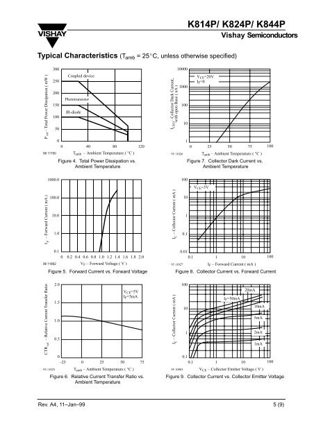
<strong>K814P</strong>/ <strong>K824P</strong>/ <strong>K844P</strong>Vishay SemiconductorsTypical Characteristics (T amb = 25 C, unless otherwise specified)P tot – Total Power Dissipation ( mW )30025020015010096 1170050Coupled device<strong>Phototransistor</strong>IR-diode00 40 80 120T amb – Ambient Temperature ( °C )Figure 4. Total Power Dissipation vs.Ambient TemperatureI CEO – Collector Dark Current,<strong>with</strong> open Base ( nA )1000095 11026100010010V CE =20VI F =010 25 50 75T amb – Ambient Temperature ( °C )Figure 7. Collector Dark Current vs.Ambient Temperature100I F – Forward Current ( mA )1000.0100.010.01.0I C – Collector Current ( mA )1001010.1V CE =5V0.10 0.2 0.4 0.6 0.8 1.0 1.2 1.4 1.6 1.8 2.096 11862V F – Forward Voltage ( V )Figure 5. Forward Current vs. Forward Voltage95 110270.010.1 1 10I F – Forward Current ( mA )100Figure 8. Collector Current vs. Forward CurrentCTR rel – Relative Current Transfer Ratio95 110252.01.51.00.50–25 0 25 50V CE =5VI F =5mAT amb – Ambient Temperature ( °C )Figure 6. Relative Current Transfer Ratio vs.Ambient Temperature75I C – Collector Current ( mA )95 10985100101I F =50mA0.10.1 1 1020mA10mA5mA2mA1mAV CE – Collector Emitter Voltage ( V )100Figure 9. Collector Current vs. Collector Emitter VoltageRev. A4, 11–Jan–99 5 (9)