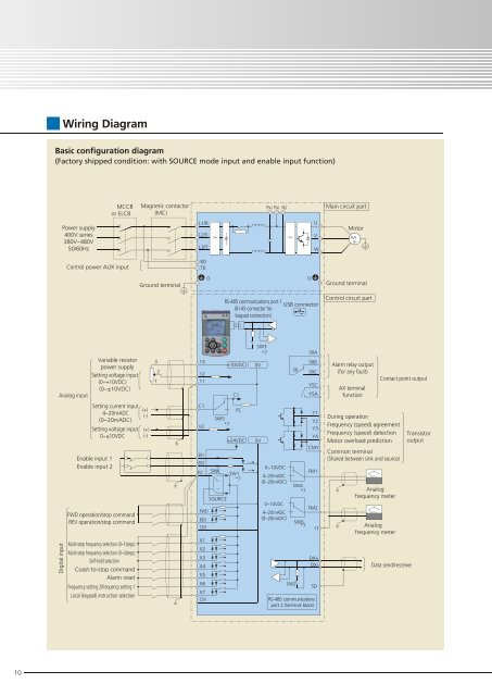
Wiring DiagramBasic configuration diagram(Factory shipped condition: with SOURCE mode input and enable input function)MCCBor ELCBMagnetic contactor(MC)P(+) P(+) N(-)Main circuit partPower supply400V series380V~480V50/60HzL1/RL2/SL3/TUVWMotorM3~Control power AUX inputR0T0Ground terminalGGGround terminalRS-485 communications port 1(RJ-45 connector forkeypad connection)USB connectorControl circuit partAnalog inputVariable resistorpower supplySetting voltage input(0~+10VDC)(0~±10VDC)312131211+10VDCC1SW3*70V3030A30B30CY5CY5AAlarm relay output(for any fault)AX terminalfunctionContact point outputDigital inputSetting current input4~20mADC(0~20mADC)Setting voltage input0~±10VDCEnable input 1Enable input 2FWD operation/stop commandREV operation/stop commandMulti-step frequency selection (0~1steps)Multi-step frequency selection (0~3steps)Self-hold selectionCoast-to-stop commandAlarm resetFrequency setting 2/frequency setting 1Local (keypad) instruction selection(+)(-)(+)(-)C1V2EN1EN2PLCFWDREVCMX1X2X3X4X5X6X7CMSW5*7SINKSOURCEPTC+24VDCSW1*70V0~10VDC4~20mADC(0~20mADC)0~10VDC4~20mADC(0~20mADC)SW2SW4*7SW6*7Y1Y2Y3Y4CMYFM1FM2RS-485 communicationsport 2 (terminal block)11DX+DX-SDDuring operationFrequency (speed) agreementFrequency (speed) detectionMotor overload predictionCommon terminal(Shared between sink and source)Analogfrequency meterAnalogfrequency meterData send/receiveTransistoroutput10
OptionsRelay output interface card (OPC-G1-RY)This is an optional card that converts the transistor output atterminals Y1 to Y4 on the inverter body to relay output (1c). Eachcard has two relay outputs, and four relay outputs are availableby installing two cards.Note: When the card is mounted, the terminals Y1 to Y4 on the inverter bodyRelay output:Signal type:2 circuits built-inContact point capacity: AC250V, 0.3A cos =0.1cDC48V, 0.5A (Resistance load)Relay output interface card (OPC-G1-RYThis optional card allows relay outputs (1a) to be added. Whenused in cascaded control, this card can control the seven motors.* By using the two relay outputs on the inverter body, max. 8 units and one unit(auxiliary pump) can be controlled.Relay output:Signal type:7 circuits built-inContact point capacity: AC250V, 0.3A cos =0.1aDC48V, 0.5A (Resistance load)2)Analog input interface card (OPC-G1-AIO)This card allows analog input and output to be used.Analog input:Analog output: 1 analog voltage output point (0~±10V)No. of connection units:Communications method: CC-Link Ver1.10 and Ver2.0Communications rate:1 analog voltage input point (0~±10V)1 analog current input point (4~20mA)1 analog current output point (4~20mA)CC-Link communications card (OPC-G1-CCL)By connecting this card with the CC-Link master unit, thecommunications rate up to 10Mbps can be supported and thetransmission distance is covered up to 1200 m in total.42 units156kbps~Analog current output interface card (OPC-G1-This card allows two analog current output (4 to 20mA) pointsAO)to be used. The card cannot be used together with OPC-G1-AIO.DeviceNet communications card (OPC-G1-DEV)This card enables operation instruction and frequency commandto be set from the DeviceNet master, allowing operationconditions to be monitored and all the function codes to bechanged and checked.No. of connection nodes: max. 64 units (including the master unit)MAC ID:Insulation:Communications rate:0~63500V DC (photocoupler insulation)500kbps/250kbps/125kbpsNetwork consumed pow: er max. 80mA, 24V DCPROFIBUS DP communications card (OPC-G1-PDP)This card enables operation instruction and frequency commandto be set from the PROFIBUS DP master, allowing operationconditions to be monitored and all the function codes to bechanged and checked.Communications rate: 9.6kbps~12MbpsTransmission distance: ~1,200mConnection connector: 6-pole terminal blockLonWorks communications card (OPC-G1-LNW)Coming soonThis card allows peripheral equipment (including a master unit)that is connected via LonWorks to be connected with theinverter, enabling operation instruction and frequency commandto be set from the master unit.CANopen communications card (OPC-G1-COP)This card enables operation instruction and frequency commandto be set from the CANopen master (such as PC and PLC),allowing all the function codes to be set and checked.No. of connection nod:es 127 unitsCommunications rate:Transmission distance: ~2,500m20k, 50k, 125k, 250k, 500k,800k, 1MbpsEthernet communications card (OPC-G1-ETH)ComingsoonPt100 temperature sensor input card (OPC-G1-PT)ComingsoonExtension cable for remote operation (CB- S)This cable is used in connection between the inverter body andthe keypad.Optional typeCB-5SCB-3SCB-1SLength (m)531Battery (OPK-BP)Used for the real time clock activated while the inverter poweris off. The real time clock can be operated even when no poweris supplied inverter at electric power interruption.11