whitegoods 100 Plaster-in Installation Instructions A3.qxd
whitegoods 100 Plaster-in Installation Instructions A3.qxd
whitegoods 100 Plaster-in Installation Instructions A3.qxd

Create successful ePaper yourself
Turn your PDF publications into a flip-book with our unique Google optimized e-Paper software.
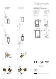
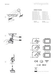
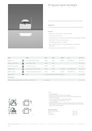
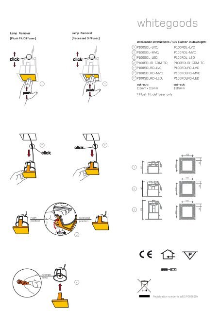
Lamp Removal(Flush Fit Diffuser)Lamp Removalclickclickpush1(Recessed Diffuser)push1<strong>whitegoods</strong><strong>in</strong>stallation <strong>in</strong>structions / <strong>100</strong> plaster-<strong>in</strong> downlight:2 P<strong>100</strong>SDL-LVC; P<strong>100</strong>RDL-LVC2 P<strong>100</strong>SDL-MVC; P<strong>100</strong>RDL-MVC2 P<strong>100</strong>SDL-LED;3* P<strong>100</strong>SDLID-CDM-TC; P<strong>100</strong>RDLID-CDM-TC1* P<strong>100</strong>SDLRD-LVC; P<strong>100</strong>RDLRD-LVC1* P<strong>100</strong>SDLRD-MVC; P<strong>100</strong>RDLRD-MVC1* P<strong>100</strong>SDLRD-LED;cut-out:115mm x 115mm* Flush fit duffuser onlyP<strong>100</strong>RDL-LEDP<strong>100</strong>RDLRD-LEDcut-out:Ø115mm2clickclick2<strong>100</strong>251115<strong>100</strong><strong>100</strong>2145<strong>100</strong>25<strong>100</strong>3180<strong>100</strong>25flushpositionrecessedpositionclick3changelamp4Registration number is WEE/FG0362QY
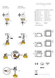
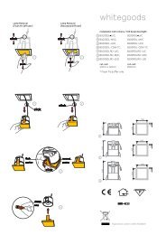
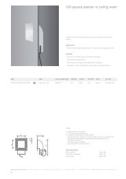
150c. gearBCBCc. gearBCc. gearBCB/CB/CB/CB/Cc. gearc. gearc. gearCLICKCLICKCLICKCLICKc. gearc. gearc. gearc. gear150AAsecutitycablecut-outP<strong>100</strong>SDL-LVC; P<strong>100</strong>RDL-LVC; P<strong>100</strong>SDL-LED; P<strong>100</strong>RDL-LED150AAsecutitycablecut-outP<strong>100</strong>SDL-MVC; P<strong>100</strong>RDL-MVC; P<strong>100</strong>SDLRD-MVC; P<strong>100</strong>RDLRD-MVC150P<strong>100</strong>SDLID-CDM-TC; P<strong>100</strong>RDLID-CDM-TCP<strong>100</strong>SDLRD-LVC; P<strong>100</strong>RDLRD-LVC; P<strong>100</strong>SDLRD-LED; P<strong>100</strong>RDLRD-LEDplasterplasterc. gearAAsecutitycablecut-out150plasterc. gear150150150AAsecutitycablecut-outplaster
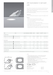
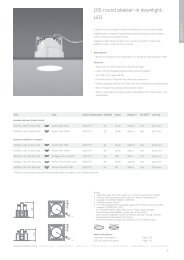
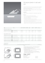
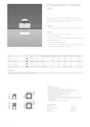
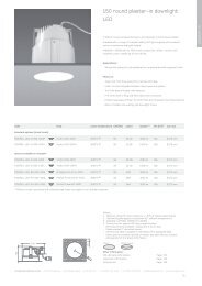
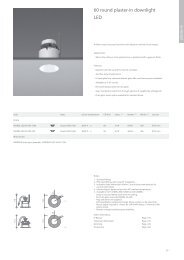
codelamptypeP<strong>100</strong>SDL-LVC; P<strong>100</strong>RDL-LVCLow voltage capsuleQTax-12P<strong>100</strong>SDL-MVC; P<strong>100</strong>RDL-MVCMa<strong>in</strong>s voltage capsuleQT14P<strong>100</strong>SDL-LED; P<strong>100</strong>RDL-LEDLight emitt<strong>in</strong>g diodeLEDP<strong>100</strong>SDLID-CDM-TC; P<strong>100</strong>RDLID-CDM-TC Ceramic discharge metal halide CDM-TCP<strong>100</strong>SDLRD-LVC; P<strong>100</strong>RDLRD-LVCLow voltage capsuleQTax-12P<strong>100</strong>SDLRD-MVC; P<strong>100</strong>RDLRD-MVCMa<strong>in</strong>s voltage capsuleQT14P<strong>100</strong>SDLRD-LED; P<strong>100</strong>RDLRD-LEDLight emitt<strong>in</strong>g diodeLEDbasewattslumencut-outGY6.3520-50 W320-930 lm115 x 115mm; Ø115mmG925-60 W260-820 lm115 x 115mm; Ø115mmTBATBATBA115 x 115mm; Ø115mmG8.5 35 W 2200 lm 115 x 115mm; Ø115mmGY6.3520-50 W320-930 lm115 x115mm; Ø115mmG925-60 W260-820 lm115 x 115mm; Ø115mmTBATBATBA115 x 115mm; Ø115mm
<strong>whitegoods</strong> ltd light<strong>in</strong>g P<strong>100</strong> S-R DL 3/6GB<strong>Installation</strong>Disconnect the ma<strong>in</strong>s supply before <strong>in</strong>stallationThis fixture is to be <strong>in</strong>stalled and ma<strong>in</strong>ta<strong>in</strong>ed by a recognised electrician.Care must be taken when plaster<strong>in</strong>g the hous<strong>in</strong>g that no excess plasteris applied on the <strong>in</strong>side of the lum<strong>in</strong>aire hous<strong>in</strong>g as this is detrimental tothe operation of the lum<strong>in</strong>aire.1. Cut-out the required recess<strong>in</strong>g aperture and screw fix the frame (A) tothe soffit. (as shown) Use a timber batten back<strong>in</strong>g to the soffit if strongerfix<strong>in</strong>g po<strong>in</strong>ts are required.2. Remove any <strong>in</strong>sulation or obstruction with<strong>in</strong> 150mm of the mount<strong>in</strong>gframe.3. <strong>Plaster</strong> the ceil<strong>in</strong>g us<strong>in</strong>g the lip of the frame as a stop bead for theplaster f<strong>in</strong>ish.4. Clean any excess plaster from <strong>in</strong>side the mount<strong>in</strong>g frame as this willhave detrimental effect on the operation of the lum<strong>in</strong>aire.Make the electrical connection as follows:Fitt<strong>in</strong>g Type: P<strong>100</strong>SDL-LVC; P<strong>100</strong>RDL-LVC; P<strong>100</strong>SDLRD-LVC;P<strong>100</strong>RDLRD-LVC;A. Remove the female 230/240v 50/60Hz 2-p<strong>in</strong> connector plug from thelum<strong>in</strong>aire and wire the plug to the secondary side of the transformer.Refer to the transformer for a detailed wir<strong>in</strong>g diagram. Use only Whitegoodssupplied transformers.B. Wire the ma<strong>in</strong>s <strong>in</strong>put to the supplied transformer, refer to thetransformer for a detailed wir<strong>in</strong>g diagram.C. Re-connect the female plug from the ma<strong>in</strong>s transformer to the maleplug attached to the lum<strong>in</strong>aire.Fitt<strong>in</strong>g Type P<strong>100</strong>SDL-MVC; P<strong>100</strong>RDL-MVC; P<strong>100</strong>SDLRD-MVC;P<strong>100</strong>RDLRD-MVCA. Unplug the female 230/240v 50/60Hz 3-p<strong>in</strong> connector from the lamp<strong>in</strong>sert and wire the ma<strong>in</strong>s cable <strong>in</strong>to position.B. Re-connect the female to male plug.Fitt<strong>in</strong>g Type: P<strong>100</strong>SDL-LED; P<strong>100</strong>RDL-LED; TBAFitt<strong>in</strong>g Type: P<strong>100</strong>SDL-CDMTC; P<strong>100</strong>SDL-CDMTC;A. Unplug the female 230/240v 50/60Hz 2-p<strong>in</strong> plug from the lamp <strong>in</strong>sertand wire the control gear secondary side to the plug. Refer to the controlgear for a detailed wir<strong>in</strong>g diagram. Use only Whitegoods supplied controlgear.B. Wire the ma<strong>in</strong>s <strong>in</strong>put to the supplied transformer, refer to thetransformer for a detailed wir<strong>in</strong>g diagram.C. Re-connect the female plug from the ma<strong>in</strong>s transformer to the maleplug attached to the lum<strong>in</strong>aire.5. Insert the specific lamp <strong>in</strong>to the lamp <strong>in</strong>sert as shown.6. Clip the glass stirrup (C) onto the lamp cartridge (B) (The glass stirrupcan be connected <strong>in</strong> a the flush or recessed position, dependant on lamptype)7. Connect the reta<strong>in</strong><strong>in</strong>g cord to the lum<strong>in</strong>aire <strong>in</strong>sert and ‘push-click’ thelamp <strong>in</strong>sert assembly (B/C) <strong>in</strong>to the frame (A)Re-lamp<strong>in</strong>g ProcedureDisconnect the ma<strong>in</strong>s power supply before re-lamp<strong>in</strong>g1. ‘Push-click’ the lamp cartridge assembly (B/C) to release from theframe (A)2. Suspend the assembly on the retention wire3. Remove the glass stirrup (C)4. Replace the lamp with<strong>in</strong> the lamp <strong>in</strong>sert (B), (dispose of lamp accord<strong>in</strong>gto specific regulations)5. Re-fit the glass stirrup to lamp <strong>in</strong>sert (The glass stirrup can beconnected <strong>in</strong> a flush or recessed position as described above)6. ‘Push-click’ the lamp <strong>in</strong>sert assembly (B/C) <strong>in</strong>to the frame (A)FR<strong>Installation</strong>Débrancher la source pr<strong>in</strong>cipale d’alimentation avant de procéder àl’<strong>in</strong>stallation.Cet accessoire doit être <strong>in</strong>stallé et entretenu par un électricien autoriséseulement.Lors du plâtrage de la maison, veiller à ne pas appliquer trop de plâtre àl’<strong>in</strong>tèrieur du logement du lum<strong>in</strong>aire, car cela pourrait compromettre lebon fonctionnement du lum<strong>in</strong>aire.1. Creuser l’ouverture de montage et fixer l’armature (A) au soffitte pardes vis comme <strong>in</strong>diqué.Appliquer une latte de bois au soffitte si despo<strong>in</strong>ts de fixation plus résistants se rendent nécessaires.2. Enlever toute isolation ou obstruction dans les 150 mm autour del’armature de montage.3. Plâtrer le plafond en se servant du bec de l’armature comme po<strong>in</strong>t deréférence pour la f<strong>in</strong>ition du plâtrage.4. Enlever l’excès de plâtre de l'armature de montage, car cela pourraitcompromettre le bon fonctionnement du lum<strong>in</strong>aire.Effectuer les connexions électriques comme suit :Types de raccordement : P<strong>100</strong>SDL-LVC; P<strong>100</strong>RDL-LVC;P<strong>100</strong>SDLRD-LVC; P<strong>100</strong>RDLRD-LVC;A. Débrancher le connecteur femelle 230/240v 50/60 Hz à 2 broches dulum<strong>in</strong>aire et connecter la prise au côté secondaire du transformateur.Consulter le schéma de câblage détaillé fourni avec le transformateur.N’utiliser que les transformateurs fournis par Whitegoods.B. Connecter l'entrée pr<strong>in</strong>cipale au transformateur fourni. Consulter leschéma de câblage détaillé fourni avec le transformateur.C. Rebrancher la prise femelle du tranformateur pr<strong>in</strong>cipal à la prise mâlecôté lum<strong>in</strong>aire.Types de raccordement : P<strong>100</strong>SDL-MVC; P<strong>100</strong>RDL-MVC;P<strong>100</strong>SDLRD-MVC; P<strong>100</strong>RDLRD-MVCA. Débranchez le connecteur femelle 230/240 v 50/60 Hz à 3 brochesdu porte-ampoule et connecter les câbles pr<strong>in</strong>cipaux en position.B. Rebrancher la prise femelle à la prise mâle.Types de raccordement : P<strong>100</strong>SDL-LED; P<strong>100</strong>RDL-LED; (ENPHASE CONCEPTUELLE)Types de raccordement : P<strong>100</strong>SDL-CDMTC; P<strong>100</strong>SDL-CDMTC;A. Débrancher la prise femelle 230/240 v 50/60 Hz à 2 broches duporte-ampoule et connecter la prise au côté secondaire de lacommande de réglage à distance. Consulter le schéma de câblagedétaillé fourni avec la commande de réglage à distance. N’utiliser queles commandes de réglage à distance fournies par Whitegoods.B. Connecter l'entrée pr<strong>in</strong>cipale au transformateur fourni. Consulter leschéma de câblage détaillé fourni avec le transformateur.C. Rebrancher la prise femelle du tranformateur pr<strong>in</strong>cipal à la prise mâlecôté lum<strong>in</strong>aire.5. Insérer la lampe dans son porte-ampoule comme <strong>in</strong>diqué.6. Fixer l’étrier du diffuseur (C) sur le porte-ampoule (B). (L’étrier dudiffuseur peut être <strong>in</strong>séré dans l'encastrement ou être enfoncé selon letype de lampe).7. Connecter le fil de rétention à l’armature du lum<strong>in</strong>aire et ensuitebloquer le porte-ampoule (B/C) dans l’armature (A).Remplacement de l’ampouleDébrancher la source pr<strong>in</strong>cipale d’alimentation avant de remplacerl’ampoule.1. Excercer une pression sur le porte-ampoule (B/C) pour le libérer del’armature (A).2. Suspendre l’ensemble par le fil de rétention.3. Enlever l’étrier du diffuseur (C)4. Remplacer l’ampoule qui se trouve dans le porte-ampoule (B).Elim<strong>in</strong>er l'ampoule conformément aux normes en vigueur dans cedoma<strong>in</strong>e.5. Repositionner l’étrier du diffuseur sur le porte-ampoule. (L’étrier dudiffuseur peut être <strong>in</strong>séré dans l'encastrement ou être enfoncé comme<strong>in</strong>diqué ci-dessus).6. Excercer une pression sur le porte-ampoule (B/C) pour qu’il sebloque dans l’armature (A).SPInstalaciónDesconecte la alimentación eléctrica antes de llevar a cabo a<strong>in</strong>stalación.Esta lum<strong>in</strong>aria debe ser <strong>in</strong>stalada y mantenida por un electricistaautorizado.Prestar atención al colocar el emplaste en la caja, tratando de que elexceso de emplaste no entre en el <strong>in</strong>terior de la caja de la lum<strong>in</strong>aria;esto es perjudicial para el funcionamiento de la lum<strong>in</strong>aria.1. Corte la abertura necesaria para empotrar la lum<strong>in</strong>aria y fije elbastidor (A) al falso techo. (como se muestra). Si se requiere una
<strong>whitegoods</strong> ltd light<strong>in</strong>g P<strong>100</strong> S-R DL 4/6fijación más segura utilice un listón de madera para reforzar el falsotecho.2. Retire el material aislante o cualquier otro obstáculo que se encuentrea una distancia de 150 mm del bastidor.3. Coloque emplaste al cieloraso según se necesite usando el rebordedel bastidor como tope para el acabado de emplaste.4. Limpie el exceso de emplaste desde el <strong>in</strong>terior del bastidor para evitarefectos perjudiciales en el funcionamiento de la lum<strong>in</strong>aria.Haga las conexiones eléctricas como se <strong>in</strong>dica a cont<strong>in</strong>uación:Acoplamientos de tipo: P<strong>100</strong>SDL-LVC; P<strong>100</strong>RDL-LVC;P<strong>100</strong>SDLRD-LVC; P<strong>100</strong>RDLRD-LVC;A. Desenchufe el conector hembra de dos patillas 230/240v 50/60Hz,de la lum<strong>in</strong>aria y empalme el toma al lado secundario del transformador.Vease el transformador para un diagrama detallado del cableado.Utilice sólo los transformadores Whitegoods sum<strong>in</strong>istrados.B. Empalme la entrada de corriente al transformador sum<strong>in</strong>istrado,vease el transformador para un diagrama detallado del cableado.C. Vuelva a conectar el toma hembra desde la alimentación del transformadoral toma macho unido a la lum<strong>in</strong>aria.Acoplamientos de tipo: P<strong>100</strong>SDL-MVC; P<strong>100</strong>RDL-MVC;P<strong>100</strong>SDLRD-MVC; P<strong>100</strong>RDLRD-MVCA. Desenchufe el conector hembra de tres patillas, 230/240v 50/60Hz,del casquillo de la bombilla y conecte en su posición el cable de entradade corriente.B. Vuelva a conectar el conector hembra al toma machoAcoplamientos de tipo: P<strong>100</strong>SDL-LED; P<strong>100</strong>RDL-LED; TBAAcoplamientos de tipo: P<strong>100</strong>SDL-CDMTC; P<strong>100</strong>SDL-CDMTC;A. Desenchufe el conector hembra de 2 patillas, 230/240v 50/60Hz, delcasquillo de la bombilla y conecte el lado secundario del aparellaje altoma. Vease el aparellaje para un diagrama detallado del cableado.Utilice sólo aparellajes sum<strong>in</strong>istrados por Whitegoods.B. Empalme la entrada de corriente al transformador sum<strong>in</strong>istrado,vease el transformador para un diagrama detallado del cableado.C. Vuelva a conectar el toma hembra desde la alimentación del transformadoral toma macho unido a la lum<strong>in</strong>aria.5. Coloque la bombilla específica en el encastre de la bombilla como semuestra.6. Enganche el estribo de vidrio (C) al casquillo de la bombilla (B) (Elestribo de vidrio se puede acoplar en la posición enrasada o empotrada,dependiendo del tipo de bombilla).7. Conecte la alimentación al casquillo y al cable de retención ypresione el conjunto de casquillo (B/C) en el bastidor (A).Cambio de la bombillaAntes de cambiar la bombilla desconecte la alimentación eléctrica.1. Presione el conjunto del casquillo (B/C) para desencajarlo delbastidor (A).2. Deje el conjunto colgando del cable de retención.3. Retire el estribo de vidrio ©.4. Cambie la bombilla dentro del casquillo (B), (deshágase de labombilla según las normas específicas).5. Vuelva a acoplar el estribo de vidrio al casquillo. (El estribo de vidriose puede acoplar en la posición rasada o empotrada).6. Resione el conjunto del casquillo (B/C) en el bastidor (A).ITAInstallazionePrima dell’<strong>in</strong>stallazione staccare le corrente.L’<strong>in</strong>stallazione e qualsiasi <strong>in</strong>tervento deve essere effettuato da unelettricista autorizzato.Fare attenzione che al momento della posa dell’<strong>in</strong>tonaco parte di questonon f<strong>in</strong>isca all’<strong>in</strong>terno del sistema di illum<strong>in</strong>azione.1. Ritagliare un’apertura e fissare il telaio (A) con delle viti al soffitto(come mostrato). Utilizzare un r<strong>in</strong>forzo <strong>in</strong> legno qualora siano necessaridei punti di fissaggio piu’ solidi.2. Rimuovere il materiale isolante o eventuali altri ostacoli nel raggio di150mm dal telaio.3. Intonacare il soffitto f<strong>in</strong>o a bordo del telaio4. Rimuovere l’eccesso di <strong>in</strong>tonaco all’<strong>in</strong>terno del telaio che altrimenticomprometterebbe un regolare funzionamento del sistema di illum<strong>in</strong>azione.Effettuare il collegamento elettrico come seguePer i modelli: P<strong>100</strong>SDL-LVC; P<strong>100</strong>RDL-LVC; P<strong>100</strong>SDLRD-LVC;P<strong>100</strong>RDLRD-LVC;A. Scollegare le presa femm<strong>in</strong>a a due sp<strong>in</strong>otti 230/240v 50/60Hz dalportalampada e cablare la presa al trasformatore.B. Collegare la corrente pr<strong>in</strong>cipale al trasformatore. Per un diagrammadi cablaggio piu’ dettagliato fare riferimento alle <strong>in</strong>dicazioni sul trasformatore.Utilizzare solo i trasformatori forniti da Whitegoods.C. Riconnettere le presa della lampada alla presa del trasformatore.Per i modelli: P<strong>100</strong>SDL-MVC; P<strong>100</strong>RDL-MVC; P<strong>100</strong>SDLRD-MVC;P<strong>100</strong>RDLRD-MVCA. Scollegare la presa femm<strong>in</strong>a a tre sp<strong>in</strong>otti 230/240v 50/60Hz dalportalampada e cablare il cavo pr<strong>in</strong>cipale nella sua posizione.B. Riconnettere le prese maschio e femm<strong>in</strong>a tra di loro.Per i modelli: P<strong>100</strong>SDL-LED; P<strong>100</strong>RDL-LED; (<strong>in</strong> fase di progettazione)Per i modelli: P<strong>100</strong>SDL-CDMTC; P<strong>100</strong>SDL-CDMTC;A. Scollegare le presa femm<strong>in</strong>a a due sp<strong>in</strong>otti 230/240v 50/60Hz dalportalampada e cablare la presa al trasformatore.B. Collegare la corrente pr<strong>in</strong>cipale al trasformatore. Per un diagrammadi cablaggio piu’ dettagliato fare riferimento alle <strong>in</strong>dicazioni sul trasformatore.Utilizzare solo i trasformatori forniti da Whitegoods5. Inserire la lampad<strong>in</strong>a adeguata all’<strong>in</strong>terno del portalampada (B)(come mostrato <strong>in</strong> figura).6. Incastrare la montatura del vetro (C) nell’apposito b<strong>in</strong>ario delportalampada (B) come mostrato <strong>in</strong> figura (puo’ essere montato a filo delsoffitto o <strong>in</strong> posizione rientrante <strong>in</strong> dipendenza anche del tipo dilampada)7. Connettere il cavo di sicurezza al portalampada e sp<strong>in</strong>gere(“push-click”) le parti assemblate (B/C) all’<strong>in</strong>terno del telaio (A).Sostituzione della lampad<strong>in</strong>aStaccare la corrente prima di sostituire la lampad<strong>in</strong>a.1. Sp<strong>in</strong>gere (“push-click”) il portalampada assemblato (B/C) perche’venga rilasciato dal telaio (A).2. Lascire pendere il portalampada utilizzando la corda di sicurezza.3. Rimuovere la montatura del vetro (C) dall’<strong>in</strong>castro.4. Sostituire la lampad<strong>in</strong>a all’<strong>in</strong>terno del portalampada (B)(utilizzare anorma con il sistema di illum<strong>in</strong>azione)5. Incastrare la montatura del vetro (C) nell’apposito b<strong>in</strong>ario delportalampada come mostrato <strong>in</strong> figura (puo’ essere montato a filo delsoffitto o <strong>in</strong> posizione rientrante <strong>in</strong> dipendenza anche del tipo dilampada)6. Connettere il cavo di sicurezza al portalampada e sp<strong>in</strong>gere(“push-click”) le parti assemblate (B/C) all’<strong>in</strong>terno del telaio (A).
important <strong>in</strong>formationterms & conditionsgeneral <strong>in</strong>stallation <strong>in</strong>formationWEEE directiveThe <strong>in</strong>stallation of these products should only be carried out by a suitably qualified electrician<strong>in</strong> accordance with the <strong>in</strong>structions supplied with the product.The draw<strong>in</strong>gs, dimensions and f<strong>in</strong>ishes of the products <strong>in</strong> this catalogue and any accompany<strong>in</strong>g<strong>in</strong>formation are purely <strong>in</strong>dicative.In order that we can cont<strong>in</strong>ue to develop <strong>in</strong>novative quality products, we believe it is of criticalimportance that we protect our ideas and visions. Therefore any <strong>in</strong>fr<strong>in</strong>gement of our <strong>in</strong>tellectualproperty will be vigorously pursued.Great care is taken to provide up to date <strong>in</strong>formation <strong>in</strong> this publication, however, due to acont<strong>in</strong>u<strong>in</strong>g programme of design and development, we reserve the right to change thesedimensions without prior notice. All dimensions for tailored and custom designed productsare as the production draw<strong>in</strong>gs and/or a pre-production sample, produced for the project andsigned off “as correct” by the client/customer. Whitegoods reserves the right to discont<strong>in</strong>ueany product <strong>in</strong> this publication at any time without prior notice. Throughout this publication,cut-out sizes refer to the aperture required when fitt<strong>in</strong>gs are mounted <strong>in</strong> soft plasterboard.For fibrous tiles, timber, metal tiles and cast-<strong>in</strong> construction, check dimensions on site, or askfor a sample. It is the customer’s responsibility to ensure compliance with specifications thatthey are contractually obliged to meet. Whitegoods does not accept liability for compliancewith any specification other than those generated by Whitegoods. Our specification, or anydata supplied <strong>in</strong> this book or other materials or data supplied by Whitegoods will be deemed asthe <strong>in</strong> force specification of that product regardless of any specification material producedby others. All photometric data supplied is taken from a standard production lum<strong>in</strong>aire testedunder ideal laboratory conditions and may vary from data taken <strong>in</strong> alternative conditions. Allcalculated light levels and/or light<strong>in</strong>g plots provided are offered for guidance only. Thecustomer must satisfy themselves that lum<strong>in</strong>aires proposed are suitable for the application<strong>in</strong>tended <strong>in</strong> all performance and physical criteria.All products are tested with stated lamp wattage. Incorrect lamp types and wattages mayeffect efficiency, create glare and seriously overheat the lum<strong>in</strong>aire.All fitt<strong>in</strong>gs are designed for normal dry <strong>in</strong>teriors, and are not recommended for use <strong>in</strong> damp orcorrosive situations, unless otherwise stated. Adequate ventilation and free air space aroundfitt<strong>in</strong>gs (<strong>in</strong> accordance with the <strong>in</strong>stallation <strong>in</strong>structions supplied with the product) will benecessary when used <strong>in</strong> conf<strong>in</strong>ed spaces where elevated temperatures will occur. Any detail ofprice or delivery lead time will be an estimate only and cannot be guaranteed. For areas requir<strong>in</strong>glum<strong>in</strong>aires of a specific <strong>in</strong>gress protection (for eg IP64) use only lum<strong>in</strong>aries stated to havethis rat<strong>in</strong>g or higher (i.e IP64 or IP65) and use <strong>in</strong> accordance with the <strong>in</strong>stallation <strong>in</strong>structions.All ‘short shipped’ or ‘damaged’ items must be advised to us with<strong>in</strong> 24 hours of delivery. Whitegoodswill not accept responsibility for claims after this time. All goods travel at thecustomer’s risk and peril. Any export<strong>in</strong>g of goods purchased must be authorised <strong>in</strong> advance <strong>in</strong>writ<strong>in</strong>g by Whitegoods. We cannot offer refunds on Custom or Tailored products, Standardproduct may be eligible for re-stock<strong>in</strong>g with<strong>in</strong> 3 months of orig<strong>in</strong>al purchase date, subject toa 30% handl<strong>in</strong>g charge. All orig<strong>in</strong>al packag<strong>in</strong>g and documentation must be present and goodsmust be <strong>in</strong> orig<strong>in</strong>al condition. No variations to these Terms shall be b<strong>in</strong>d<strong>in</strong>g unless agreed <strong>in</strong>writ<strong>in</strong>g between the authorised representatives of the Buyer and the Seller.Whitegoods will endeavour to fulfil all orders as quickly as possible and treat all customerswith the highest regard. For further <strong>in</strong>formation about Whitegoods products and services,please visit www.<strong>whitegoods</strong>.com.Ceil<strong>in</strong>g void depths for recessed downlighters and l<strong>in</strong>ear lum<strong>in</strong>aires. The Ceil<strong>in</strong>g void depthshould ideally be 25mm deeper than the overall height of the lum<strong>in</strong>aire. When a fire-hoodand/or a remote emergency pack is to be used, the void depth and space surround<strong>in</strong>g thelum<strong>in</strong>aire will need to be <strong>in</strong>creased.When <strong>in</strong>stall<strong>in</strong>g Downlighters types 60, <strong>100</strong> 150, fitted with a bezel, <strong>in</strong>to metal tile ceil<strong>in</strong>gs,please contact the Technical Department of Whitegoods for detailed <strong>in</strong>stallation <strong>in</strong>formationand <strong>in</strong>structions.The Waste Electrical and Electronic Equipment Directive (WEEE Directive) is the EuropeanCommunity directive 2002/96/EC on waste electrical and electronic equipment, together withthe RoHS Directive 2002/95/EC which became European Law <strong>in</strong> February 2003, sett<strong>in</strong>g collection,recycl<strong>in</strong>g and recovery targets for all types of electrical goods. This imposes responsibilityfor the disposal of waste electrical and electronic equipment (WEEE) on the manufacturersof such equipment. To meet these targets Whitegoods has become a member of Lumicomto allow us to meet the current and future directives. For further <strong>in</strong>formation on the WEEEdirective please contact our offices.Registration number is WEE/FG0362QY