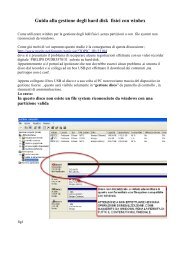
TDA8139 - Mari TV Elettronica
TDA8139 - Mari TV Elettronica
TDA8139 - Mari TV Elettronica

You also want an ePaper? Increase the reach of your titles
YUMPU automatically turns print PDFs into web optimized ePapers that Google loves.
k field, A central simple algebra over k.n ≤ 2: SK n (A) = Ker(K n (A) Nrd−→ K n (k)).Nrd = reduced norm (for n = 2, defined by Suslin via the Merkurjev-Suslin theorem).
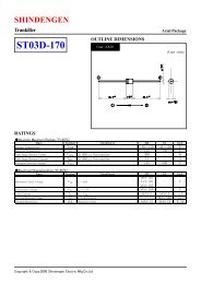
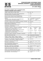
<strong>TDA8139</strong>ELECTRICAL CHARACTERISTICS ( VIN = 7V ; Tj = 25 o C unless otherwise specified)Symbol Parameter Test Conditions Min. Typ. Max. UnitVRL Saturation Volt. at Pin 6 in Reset Condition I5 = 5mA 0.4 VI RH Leakage Current at Pin 6 in Normal Condition V 5 = 10V 10 µAKO1,2 Output Volt. Thermal Drift∆Vo ⋅ 106100 ppm/°CK 0 =∆T ⋅ V OTj = 0 to + 125°CI O1,2 sc Short Circ. Ouput Current V IN = 7V 1.6 AV IN = 16V, (see note 1) 1 AV DISH Disable Volt. at Pin 4 High (out 2 active) 2 VV DISL Disable Volt. at Pin 4 Low (out 2 disabled) 0.8 VI DIS Disable Bias Current at Pin 4 0V < V DIS < 7V -100 2 µAV ref Pin 7 2.5 VT jsd Junction Temp. for Thermal Shut Down 145 °CNote 1 : The output short circuit currents are tested one channel at time.During a short circuit a large consumption of power occurs, but the thermal protection circuit prevents any excessive temperature.Safe permanent short-circuit is only guaranteed for input voltages up to 16V.Figure 18139-04.TBL10µAOUT 19REF2.5V+-a503-+bRESET6REGC e2.5V 0.6V8139-03.EPSFigure 25.1V4.9V4.85V∆VOUT LOWRESETT DT D8139-04.EPS3/5
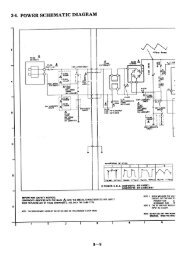
<strong>TDA8139</strong>CIRCUIT DESCRIPTIONThe <strong>TDA8139</strong> is a dual voltage regulator with Resetand Disable.The two regulation parts are supplied from onevoltage reference circuit trimmed by zener zapduring EWS test. Since the supply voltage of thislast is connected at Pin 1 (V IN1), the regulator 2 willnot work if the Pin 1 is not supplied.The outputs stages have been realized in darlingtonconfiguration with a drop typical of 1.2V.The disable circuit, switch-off the output 2 if avoltage lower than 0.8V is applied at pin 4.The Reset circuit checks the voltage at the output1. If this one goes below V OUT - 0.25V (4.85V Typ.),the comparator "a" (see Figure 1) discharges rapidlythe capacitor Ce and the reset output goes atonce low. When the voltage at the OUT 1 risesabove V OUT -0.2V (4.9V Typ.), the voltage V Ceincreases linearly to 2.5V corresponding to a delayCe ⋅ 2.5Vt d following the low : t d = (see figure 2),10µAthen the reset output goes high again. To avoidglitches in the reset output, the second comparator"b" has a large hysteresis (1.9V).TYPICAL APPLICATIONRESETCe0.1µFR1 + R2V O2 = V REFR 1typ. val R1 = 2.2Ω6 3V IN1V IN212<strong>TDA8139</strong>98V O1V O25 4 7C1 C2 C3C4R2DISABLER1C1 to C4 = 10µF8139-05.EPS4/5
<strong>TDA8139</strong>PACKAGE MECHANICAL DATA9 PINS - PLASTIC SIPDL3c2CL1NMLL2Ad1a11 9e3Bb3b1ec1PM-SIP9.EPSDimensionsMillimetersInchesMin. Typ. Max. Min. Typ. Max.A 7.1 0.280a1 2.7 3 0.106 0.118B 24.8 0.976b1 0.5 0.020b3 0.85 1.6 0.033 0.063C 3.3 0.130c1 0.43 0.017c2 1.32 0.052D 21.2 0.835d1 14.5 0.571e 2.54 0.100e3 20.32 0.800L 3.1 0.122L1 3 0.118L2 17.6 0.693L3 0.25 0.010M 3.2 0.126N 1 0.039SIP9.TBLInformation furnished is believed to be accurate and reliable. However, SGS-THOMSON Microelectronics assumes no responsibilityfor the consequences of use of such information nor for any infringement of patents or other rights of third parties which may resultfrom its use. No licence is granted by implication or otherwise under any patent or patent rights of SGS-THOMSON Microelectronics.Specifications mentioned in this publication are subject to change without notice. This publication supersedes and replaces allinformation previously supplied. SGS-THOMSON Microelectronics products are not authorized for use as critical components in lifesupport devices or systems without express written approval of SGS-THOMSON Microelectronics.© 1994 SGS-THOMSON Microelectronics - All Rights ReservedPurchase of I 2 C Components of SGS-THOMSON Microelectronics, conveys a license under the PhilipsI 2 C Patent. Rights to use these components in a I 2 C system, is granted provided that the system conforms tothe I 2 C Standard Specifications as defined by Philips.SGS-THOMSON Microelectronics GROUP OF COMPANIESAustralia - Brazil - China - France - Germany - Hong Kong - Italy - Japan - Korea - Malaysia - Malta - MoroccoThe Netherlands - Singapore - Spain - Sweden - Switzerland - Taiwan - Thailand - United Kingdom - U.S.A.5/5