Ï Ï Ï Ï Ï Ï Ï Ï Ï ÏLj
Ï Ï Ï Ï Ï Ï Ï Ï Ï ÏLj
Ï Ï Ï Ï Ï Ï Ï Ï Ï ÏLj

Create successful ePaper yourself
Turn your PDF publications into a flip-book with our unique Google optimized e-Paper software.
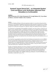
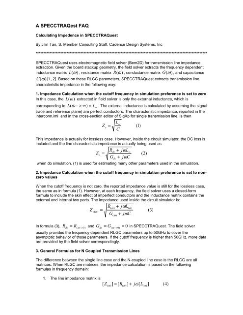
A SPECCTRAQest FAQCalculating Impedence in SPECCTRAQuestBy Jilin Tan, S. Member Consulting Staff, Cadence Design Systems, Inc***************************************************************************************************************SPECCTRAQuest uses electromagnetic field solver (Bem2D) for transmission line impedanceextraction. Given the board stackup geometry, the field solver extracts the frequency dependentinductance matrix L (ω ) , resistance matrix R (ω ) , conductance matrix G (ω ) , and capacitanceC (ω)[1, 2]. Based on these RLCG parameters, SPECCTRAQuest extracts transmission linecharacteristic impedance in the following way:1. Impedance Calculation when the cutoff frequency in simulation preference is set to zeroIn this case, the L(ω ) extracted in field solver is only the external inductance, which iscorresponding to L( ω − > ∞)= L∞. The external inductance is calculated by assuming the signaltrace and reference plane) are perfect conductors. The characteristic impedance, reported in theinterconn.iml and in the cross-section editor of SigXp for single transmission line, is thenL∞Z c=(1)CThis impedance is actually for lossless case. However, inside the circuit simulator, the DC loss isincluded and the line characteristic impedance is actually being used asRdc+ jωL∞Zc=(2)G + jωCdcwhen do simulation. (1) is used for estimating many other parameters used in the simulation.2. Impedance Calculation when the cutoff frequency in simulation preference is set to nonzerovaluesWhen the cutoff frequency is not zero, the reported impedance value is still for the lossless case,the same as in formula (1). However, at each frequency, the field solver uses a closed-formformula to include the skin effect of imperfect conductors and the inductance matrix contains theexternal and internal two parts. The impedance used inside the circuit simulator is:R(ω )+ jωL(ω )Z c ( ω )=(3)G + j ω C= R( ω − >0)( ω )R dc0dc= G( ω − > 0)=In formula (3), and G in SPECCTRAQuest. The field solverusually provides the frequency dependent RLGC parameters up to 50GHz to cover theasymptotic behavior of those parameters. If the cutoff frequency is higher than 50GHz, more dataare provided by the field solver correspondingly.3. General Formulas for N Coupled Transmission LinesThe difference between the single line case and the N-coupled line case is the RLCG are allmatrices. When RLGC are matrices, the impedance calculation is based on the followingformulas in frequency domain:1. The line impedance matrix is[ Z( ω )]= [ R(ω )]+ jω[L(ω )](4)
2. The line admittance matrix is[ Y( ω )]= [ G(ω )]+ jω[C(ω )]3. Find a similarity transformation matrix such that⎡zm(1,1)0 L 0 ⎤ ⎡Z(ω )1,1Z⎢0 z⎥ ⎢(2,2)Z()2,1ZZm ⎢mO M⎥ tT ⎢ ω==⎢ M O O 0 ⎥ ⎢ M M⎢⎥ ⎢⎢⎣0 L 0 zm(n,n)⎥⎦⎢⎣Z(ω ) n,1Zand( ω )1,2( ω )2,2( ω )2, n[ ] [ ] ⎥[ T ] (6)⎡y⎢0m(1,1)y0LO0( ω )1,1( ω ) n,2( ω )1,2(5)LLOLZZZ( ω )1, nM( ω ) n,nm(2,2)1 ( )2,1 ( )2,2( )2, n t[ Ym] ⎢⎥ −[ T ] ⎢ ω ωω ⎥ −==[ T ] (7)⎡Y⎢Y⎢ M O O 0 ⎥ ⎢ M M⎢⎥ ⎢⎢⎣0 L 0 ym(n,n)⎥⎦⎢⎣Y(ω ) n,1Y4. Find the complex propagation factor matrix2⎡γ10 L 0 ⎤⎢ 2 ⎥2 00[ ] ⎢ γ LΓ1m=⎥ = [ Zm][ Ym] (8)⎢ M M O M ⎥⎢2⎥⎢⎣0 0 L γ1 ⎥⎦5. Finally, the characteristic impedance can be calculated from:−1−1Zc = [ Z ][ T ] Γ T (9M⎤⎥[ ] [ ] [ ] )( ω )mYY( ω ) n,2LLOLYYY( ω )1, nM( ω ) n,nThe accuracy of the transmission line impedance so calculated depends on very much the RLCGmatrices extracted in the BEM2D field solver. This field solver, basically is under staticassumption and the skin effect is included under Quasi-tem Approximation of a single line modelin a closed form[2].4. References1. K. Oh, D. Kuznetsov, and J. Schutt-Aine, “Capacitance Computation in a MutilayeredDielectric Medium Using Closed-Form Spatial Green’s Functions,” IEEE, MTT, Vol.42, No. 8, pp. 1443-1453, August, 1994.2. A. Djordjevic and T. Sarkar, “Closed-Form Formulas for Frequency-DependentResistance and Inductance per Unit Length of Microstrip and Strip TransmissionLines,” IEEE, MTT, Vol. 42, No. 2, pp. 241-248, Feb., 1994.⎤⎥⎥⎥⎥⎦⎤⎥⎥⎥⎥⎦