TMP1700/090 DATASHEET - Telesis Technologies, Inc.
TMP1700/090 DATASHEET - Telesis Technologies, Inc.
TMP1700/090 DATASHEET - Telesis Technologies, Inc.

Create successful ePaper yourself
Turn your PDF publications into a flip-book with our unique Google optimized e-Paper software.
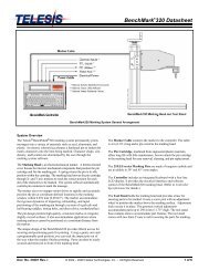
Merlin II Visual Design Software<br />
The marking system software runs on the system PC and connects to<br />
the controller via the USB port. It provides a 32-bit user interface to<br />
design pattern files and to operate the marker. The software is an<br />
easy-to-use, graphical-design application that provides tools for<br />
creating, saving, loading, and editing user-defined patterns. Each<br />
pattern contains one or more fields; each field defines a single object.<br />
Printable objects may be created to define text strings, arc-text<br />
strings, geometric shapes , graphics, and machine-readable data<br />
matrix symbols. Non-printable objects may be defined to specific<br />
commands to the marker (e.g., Pause, Go to, Input, or Output).<br />
Printable text fields may include alphanumeric characters, symbols,<br />
and special message flags. Message flags automatically insert data<br />
into the text string, such as serial numbers, times, dates and userdefined<br />
codes.<br />
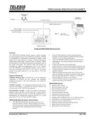
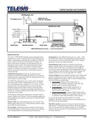
I/O Control Signals. The TMC<strong>090</strong> is configured for DC I/O only.<br />
The TTL Input port may be used to connect a remote push button<br />
control for sending Start Print and Abort commands to the marker.<br />
The I/O port may be used to connect a PLC or other DC I/O source.<br />
The I/O port allows remote control of printing, aborting, placing<br />
the marker online, and monitoring of the Ready and Done output<br />
signals. Additionally, the I/O port allows for remote pattern<br />
selection. The marking system can monitor four separate input<br />
signals and, based on the on/off state of those signals, will select<br />
and open a specific pattern stored on the PC.<br />
Cable connectors and connector pins are supplied with the controller<br />
for constructing appropriate interface cables.<br />
START PRINT Input signal: begin print cycle<br />
SEL_0, 1, 2, 3 Input signals: pattern selection<br />
ABORT Input signal: abort print cycle<br />
INPUT COMM For all inputs (+ or – supply)<br />
READY Output signal: ready for message or start print<br />
DONE Output signal: print cycle complete<br />
OUTPUT COMM For all outputs (+ or – supply)<br />
<strong>TMP1700</strong>/<strong>090</strong> <strong>DATASHEET</strong><br />
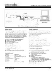
Host Communications. The marking system software allows you to<br />
configure communication parameters to transmit and receive data to<br />
and from a host computer or a remote I/O device. The host<br />
communicates with the marking system software via the host<br />
interface on the system PC. The software passes information to and<br />
from the marking equipment via the controller USB interface. To<br />
provide maximum integration flexibility, the system software<br />
supports Ethernet (TCP/IP) interfaces and serial (RS-232) interfaces.<br />
It also provides two protocol choices: Programmable Protocol and<br />
Extended Protocol.<br />
TCP/IP Interface. The Ethernet (TCP/IP) interface is most often<br />
used with host computers communicating over a local area network<br />
(LAN). With this type of interface, you may use either Extended<br />
Protocol or Programmable Protocol.<br />
The Port parameter identifies the host computer socket that is<br />
assigned to the marking system. If more than one marking system<br />
is installed in a network configuration, each system must use a<br />
separate and unique port number. The Address parameter identifies<br />
the IP (Internet Protocol) address of the host computer. The<br />
marking system software supports both fixed addressing and<br />
dynamic addressing.<br />
RS-232 Interface. The serial (RS-232) communications interface<br />
is most often used with remote devices such as host computers,<br />
terminals, or bar code scanners. The RS-232 interface supports both<br />
Extended Protocol and Programmable Protocol.<br />
The following describes the serial data character format on all<br />
transmissions to and from the TMC<strong>090</strong> controller.<br />
• Asynchronous<br />
• 300, 600, 1200, 2400, 4800, 9600, 19200, 38400,<br />
57600, or 115200 Baud<br />
• 1, 1.5, or 2 Stop Bits<br />
• 5, 6, 7, or 8 Data Bits<br />
• None, Even or Odd Parity<br />
Doc. No. 33522 Rev. H 6 of 7