Terabit/Second Modulation Format Independent Optical Transmitter ...
Terabit/Second Modulation Format Independent Optical Transmitter ...
Terabit/Second Modulation Format Independent Optical Transmitter ...

You also want an ePaper? Increase the reach of your titles
YUMPU automatically turns print PDFs into web optimized ePapers that Google loves.
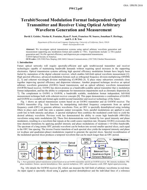
PWC2.pdfa392_1.pdfOSA / IPR/PS 2010<strong>Terabit</strong>/<strong>Second</strong> <strong>Modulation</strong> <strong>Format</strong> <strong>Independent</strong> <strong>Optical</strong><strong>Transmitter</strong> and Receiver Using <strong>Optical</strong> ArbitraryWaveform Generation and MeasurementDavid J. Geisler, Nicolas K. Fontaine, Ryan P. Scott, Francisco M. Soares, Jonathan P. Heritage,and S. J. B. YooDepartment of Electrical and Computer Engineering, University of California, Davis, 95616Email: sbyoo@ucdavis.eduAbstract: We investigate optical transmission systems using optical arbitrary waveform generation andmeasurement supporting any modulation format and scalable to >Tb/s. Experiments include 1.2 Tb/s packetgeneration and 3 b/s/Hz spectral efficiency and dispersion pre-compensated transmission.©2010 <strong>Optical</strong> Society of AmericaOCIS codes: (320.5540) Pulse Shaping; (060.1660) Coherent Communications; (320.7100) Ultrafast Measurements.1. IntroductionFuture optical networks will require spectrally-efficient and agile terabit/second transmitter and receivertechnologies capable of maintaining bandwidth demands without requiring speed increases in the supportingelectronics. <strong>Optical</strong> transmission systems utilizing high spectral efficiency modulation formats have largely beenfueled by maturation of the digital coherent receiver, which enables full-field optical waveform measurement [1].High spectral efficiency, advanced modulation formats such as orthogonal frequency division multiplexing (OFDM)[2, 3] and coherent wavelength division multiplexing (CoWDM) [4, 5] place many subcarriers extremely closetogether improving spectral efficiency and dispersion tolerance. Another proposed technique involves an opticalarbitrary waveform generation (OAWG) based transmission, and an optical arbitrary waveform measurement(OAWM) based receiver. OAWG has shown promise as a bandwidth-scalable optical transmitter that is modulationformat independent, and has the ability to compensate for transmission impairments such as chromatic dispersion [6,7]. The complement to OAWG is OAWM, a bandwidth scalable, modulation format independent, full-fieldmeasurement technique built with coherent receiver concepts [8]. This paper demonstrates a combination of OAWGand OAWM as a scalable and format-agile terabit/second transmitter and receiver technology of the future.Fig. 1 shows an optical transmission system based on an OAWG transmitter and an OAWM receiver. TheOAWG transmitter (Fig. 1(a)) functions by manipulating individual frequency components from an opticalfrequency comb (OFC) to generate arbitrary waveforms. First, an OFC is spectrally demultiplexed using isolatingfilters to place each comb line onto a separate output waveguide. Next, parallel modulations are applied to eachcomb line in both intensity and phase. A spectral multiplexer then combines the modulated comb lines to yield thedesired arbitrary waveform. Previous work has demonstrated the ability to create high bandwidth (400 GHz)waveforms using static modulations [6]. These first demonstrations were limited by low speed intensity and phasemodulators, resulting in a waveform that repeats at the comb source repetition rate. Dynamic OAWG overcomes thistime duration limitations by applying parallel intensity and phase modulations of moderate (~10 GHz) bandwidth.The spectrum of a long (many OFC periods) waveform can be broken into several smaller spectral slices, each equalto the OFC line spacing. The inverse Fourier transform of each spectral slice yields the temporal intensity and phase(or in-phase and quadrature-phase) modulations required to generate the spectral slices. Spectral recombination ofthe modulated spectral slices produces a temporal waveform that can be much longer than an OFC period.DemuxMuxDemuxFig. 1. Next generation optical transmission system based on (a) an OAWG transmitter and (b) an OAWM receiver. IM: intensity modulator. PM:phase modulator. Demux: spectral demultiplexer. Mux: spectral multiplexer. OFC: optical frequency comb. DSP: digital signal processing.Fig. 1(b) details the OAWM receiver [8], which can measure the full field of arbitrary waveforms in real-time.An input signal is spectrally sliced using a gapless spectral demultiplexer and the individual lines of a reference
PWC2.pdfa392_1.pdfOSA / IPR/PS 2010OFC are isolated using a second spectral demultiplexer. In a parallel operation, each spectral slice is demodulated tothe baseband using a single reference OFC line and a balanced four-quadrature coherent receiver based on a 90ºdegree optical hybrid. Sampling the in-phase and quadrature components of the resultant electrical signals above theNyquist rate enables full field characterization of each spectral slice. DSP then combines the spectral slices togetheryielding the complete waveform. Fontaine et al. successfully demonstrated measurements of a 160 GHz arbitrarywaveform measurement with a 2 s record length with potential for continuous measurement.2. ExperimentFig. 2 shows a 1.2 Tb/s 16QAM shaped waveform packet with a spectral efficiency of 3 b/s/Hz generated usingstatic OAWG methodology (repetitive waveform generation). Measurements were taken using frequency resolvedoptical gating, an averaged measurement technique [9]. A 40 comb line, 10 GHz OFC provided the input to the 64channel, 10 GHz spacing silica OAWG device. The digital signal process (DSP) controller determined the intensityand phase values corresponding to the target 16QAM waveform. First, the DSP creates a series of delta functionscentered at each symbol location. Next, the intensity and phase value corresponding to the desired symbol (4-bits) isapplied to each delta function. The symbol train is band-limited using a raised cosine modulation filter with a -rolloff factor of 0.5, as a compromise between spectral efficiency and waveform fidelity. At this point, optionalchromatic dispersion compensation can be incorporated into the target signal by adjusting the spectral phase anamount inverse to the link transmission function.Fig. 2(a) shows the rapid variations in intensity and phase between comb lines. The corresponding time domain(Fig. 2(b)) has 16 possible modulation format symbols, which need to be accurately specified at the transmitter.Spectral shaping errors due to optical and thermal crosstalk in the device are apparent from the slight mismatchbetween the target and measured data. Fig. 2(c,d) show the target and measured constellation diagrams. Waveformshaping error caused some of the measured constellation points to blur causing errors. Fig. 2(e) shows the measuredconstellation diagram after correcting for all spectral phase errors, which eliminates the symbol errors. OAWGdevices with reduced optical and thermal crosstalk foreshadows the potential for an OAWG transmitter to generatewaveforms at single channel data rates >1 Tb/s.Quadrature-phaseQuadrature-phaseQuadrature-phaseIntensity (5 dB/div)Phase (1 rad/div)Intensity (a.u.)Phase (1 rad/div)Fig. 2. 120 bit 1.2 Tb/s NRZ-QAM packet. (a) Spectral intensity (blue stems) and phase (red circles) with targets indicated by blue (intensity) andred (phase) ‘x’ symbols. (b) Time domain optical field intensity (solid blue line) and phase (red dots). Target intensity and phase indicated byblue and red dashed lines, respectively. Constellation diagrams of (c) target data, (d) measured data and (e) measured data with spectral phasecorrection. [6]Advancing to dynamic OAWG requires optical modulators capable of modulations on the order of the combsource spacing. The OAWG technology utilizes many (~100 ch) lower speed (~10 GHz) electronics to achieve highcapacity (~1 Tb/s). Due to the complexity and crosstalk from conventional electronic interconnections, the ~ 1 Tb/sOAWG will exploit optically-interconnected cross phase modulation (XPM) of InP based Michelson devices (~100ch) monolithically integrated on the InP photonic integrated circuit (PIC) platform. Fig. 3(a) shows the schematic ofa reflection based OAWG device with Michelson structures on each output channel and Fig. 3 (b) shows recentlyfabricated 2-inch InP monolithic PIC containing 100 ch x 10 GHz arrayed waveguide grating (AWG) and 100 chMichelson XPM devices. In Fig 3(a), the highly-reflective (HR) surface allows folding of the architecture in Fig 1(a) to use one AWG for both Demux and Mux of 100 channels, and also allows amplitude and phase modulation byXPM in Michelson devices. In this case, the 1550 nm phase modulation on each arm is caused by excess carriers
PWC2.pdfa392_1.pdfOSA / IPR/PS 2010introduced from the absorption of 1064 nm light. The highly reflective surface reflects the 1550 nm light, while alsominimizing reflection for 1064 nm light. Amplitude modulation is achieved by modulating only one Michelson armwhile phase modulation requires simultaneous modulation of both arms. Future devices based a nested Michelsonstructure will enable in-phase and quadrature-phase (IQ) modulations of each comb line, which reduces the opticalbandwidth requirement on each modulator to 5 GHz to construct a 10 GHz spectrum.Fig. 3(b) shows the experimental arrangement for measuring the dynamic XPM of the reflection basedMichelson structure. A reverse bias voltage was used to set the modulation point on the sinusoidal squaredMichelson transfer function. A variable rf source directly modulated the 1064 nm laser. For each rf source frequency,a heterodyne optical spectrum analyzer was used to measure the 1550 nm Michelson response. The frequencyresponse of the Michelson structure at various bias voltages. Increasing the magnitude of the bias voltage to -10 Vthe Michelson structure allowed relatively flat frequency response of the absorption induced XPM to ~5 GHz. Thefull 100 ch x 10 GHz dynamic OAWG based terabit/second experiment is in progress.(c)Fig. 3. (a) Schematic of reflection based OAWG device based on Michelson modulators. (b) Experimental arrangement for dynamic cross phasemodulation of InP reflection based Michelson structure. (c) 2-inch 100 ch x 10 GHz InP OAWG chip for > 1Tb/s transmitter. Colors indicatereverse bias voltages. Demux: spectral demultiplexer.3. ConclusionStatic OAWG transmission of a 120-bit, 1.2 Tb/s 16QAM waveform indicates the potential for >1 Tb/s transmissionsystems. Our recent results show the potential for monolithically integrated >1 Tb/s dynamic OAWG chipcontaining 100ch x 10 GHz AWG and 100 ch XPM Michelson optical modulators. Additionally, we have proposedutilizing the bandwidth-scalable OAWG transmitter and OAWM receiver for future optical networks.References[1] E. Ip, A. P. T. Lau, D. J. F. Barros, and J. M. Kahn, "Coherent detection in optical fiber systems," Opt. Express, vol. 16, pp. 753-791,2008.[2] S. L. Jansen, I. Morita, T. C. W. Schenk, N. Takeda, and H. Tanaka, "Coherent optical 25.8-Gb/s OFDM transmission over 4160-kmSSMF," J. Lightw. Technol., vol. 26, pp. 6-15, 2008.[3] Q. Yang, Y. Yang, Y. Ma, and W. Shieh, "Experimental Demonstration and Numerical Simulation of 107-Gb/s High SpectralEfficiency Coherent <strong>Optical</strong> OFDM," J. Lightw. Technol., vol. 27, pp. 168-176, 2009.[4] A. D. Ellis and F. C. G. Gunning, "Spectral density enhancement using coherent WDM," IEEE Photon. Technol. Lett., vol. 17, pp.504-506, 2005.[5] F. C. G. Gunning, T. Healy, and A. D. Ellis, "Dispersion tolerance of coherent WDM," IEEE Photon. Technol. Lett., vol. 18, pp.1338-1340, 2006.[6] D. J. Geisler, N. K. Fontaine, T. He, R. P. Scott, L. Paraschis, J. P. Heritage, and S. J. B. Yoo, "<strong>Modulation</strong>-format agile,reconfigurable Tb/s transmitter based optical arbitrary waveform generation," Opt. Express, vol. 17, pp. 1-15, 2009.[7] D. J. Geisler, N. K. Fontaine, R. P. Scott, T. He, J. P. Heritage, and S. J. B. Yoo, "Single Channel, 200 Gb/s, Chromatic DispersionPrecompensated 100 km Transmission Using an <strong>Optical</strong> Arbitrary Waveform Generation Based <strong>Optical</strong> <strong>Transmitter</strong>," in Proc. of OFC2010, Mar. 21-25, 2010, paper OWO4.[8] N. K. Fontaine, R. P. Scott, L. Zhou, F. M. Soares, J. P. Heritage, and S. J. B. Yoo, "Real-time full-field arbitrary optical waveformmeasurement," accepted for publication in Nature Photon., 2010.[9] R. P. Scott, N. K. Fontaine, J. Cao, K. Okamoto, B. H. Kolner, J. P. Heritage, and S. J. B. Yoo, "High-fidelity line-by-line opticalwaveform generation and complete characterization using FROG," Opt. Express, vol. 15, pp. 9977-9988, 2007.[10] F. M. Soares 1 , J. H. Baek 1 , N. K. Fontaine 1 , C. Junesand 2 , S. Lourdudoss 2 , K.Y. Liou 3 , R. A. Hamm 3 , W. Wang 3 , B. Patel 3 , W.S.Hobson 3 , J. R. Lothian 3 , S. Vatanapradit 3 , L. A. Gruezke 3 , W. T. Tsang 3 , and S. J. B. Yoo 1 , "Monolithically Integrated InP Wafer-Scale 100-Channel 10-GHz AWG and Michelson Interferometers for 1-THz-Bandwidth <strong>Optical</strong> Arbitrary Waveform Generation,"to appear in Technical Digest, <strong>Optical</strong> Fiber Communication Conference 2010, Paper ThS1.This work was supported in part by the DARPA DSO and SPAWAR under OAWG contract HR0011-05-C-0155.