EMI filters - dovercmp.com
EMI filters - dovercmp.com
EMI filters - dovercmp.com

You also want an ePaper? Increase the reach of your titles
YUMPU automatically turns print PDFs into web optimized ePapers that Google loves.
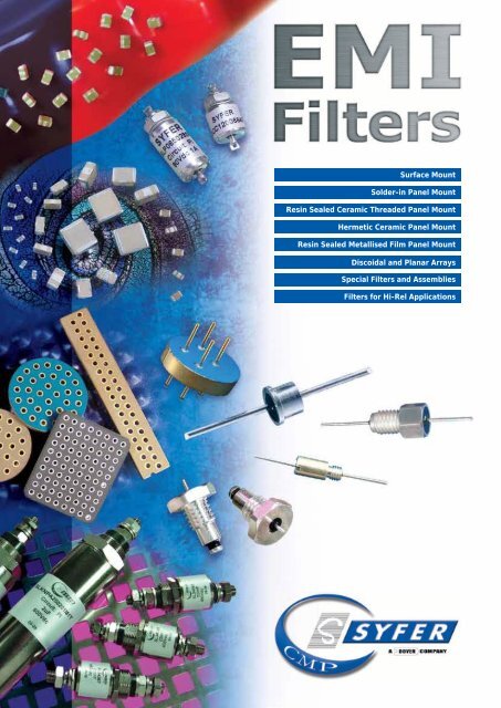
Surface MountSolder-in Panel MountResin Sealed Ceramic Threaded Panel MountHermetic Ceramic Panel MountResin Sealed Metallised Film Panel MountDiscoidal and Planar ArraysSpecial Filters and AssembliesFilters for Hi-Rel Applications
Introduction to Syfer TechnologySyfer Technology Limited is a global <strong>com</strong>pany dedicated tothe manufacture of ceramic based electronic <strong>com</strong>ponents.Syfer has been producing Multilayer Ceramic Capacitors forover 25 years and its employees are <strong>com</strong>mitted to providingcustomers with high quality products together with a fast,friendly and flexible service from a state-of-the-art facility.Production processAt the core of Syfer’s ceramic manufacturing technology isthe ‘Wet Process’. This fully integrated <strong>com</strong>puter-controlledmanufacturing operation is in a clean room environment,and offers unique advantages in the manufacture of filterproducts. This has resulted in Syfer being a world leaderin the manufacture of <strong>EMI</strong> <strong>filters</strong>, discoidal capacitors andplanar arrays. Our multilayer ceramic manufacturing facilityand filter assembly facility holds a number of internationallyrecognised approvals including ISO 9001:2008, IS014001:2004 and OHSAS 18001:2007. Syfer is also an ESA(European Space Agency) and NASA approved source.Specific product approvals/qualifications include IECQ CECC,UL, TÜV and AEC-Q200.ProductsSyfer’s excellence in ceramic materials technology, <strong>com</strong>binedwith <strong>EMI</strong> filter expertise, has enabled us to offer anunrivalled range of <strong>EMI</strong> filter products including:● Surface Mount <strong>filters</strong> including:Feedthrough Chip capacitorsSurface Mount C <strong>filters</strong>Surface Mount Pi <strong>filters</strong>X2Y - Integrated Passive Components● Solder-in Panel Mount <strong>filters</strong>● Resin Sealed Ceramic Threaded Panel Mount <strong>filters</strong>● Hermetic Ceramic Panel Mount <strong>filters</strong>● Resin Sealed Metallised Film Panel Mount <strong>filters</strong>● Discoidal capacitors● Planar capacitor and Planar Varistor Arrays● Special filter assembly capabilityBenefitsSurface Mount <strong>EMI</strong> <strong>filters</strong>● High capacitance, high voltage, high current Pi <strong>filters</strong>● FlexiCap termination an option● AEC-Q200 qualificationsPanel Mount <strong>EMI</strong> <strong>filters</strong>● Use of X7R and C0G/NP0 ceramics - no Z5U● High capacitance values, high voltage● Use of self-healing plastic film material● High frequency performance to 10GHzX2Y● Available with FlexiCap termination● AEC-Q200 and medical implantable● Available in surface mount, panel mount and planararray versionsDiscoidal capacitors● Small sizes, high capacitance values, high voltagecapability● Custom sizes available● Varistor discoidal optionsPlanar arrays● Mechanical superiority, tighter mechanical tolerances● High voltage capability, mixed capacitance values● NASA approved● Available in capacitor, varistor, inductor and X2Y formatsMultiway filter assemblies● Can use either discoidal capacitor elements orplanar arrays● Full custom design facilityOther Syfer products● Multilayer ceramic chip capacitors● High voltage MLCCs● ProtectiCap capacitors● FlexiCap capacitors with flexible terminations● StackiCap capacitors● Class ‘X’ and ‘Y’ SMD Safety Certified capacitors● Radial leaded capacitors● AEC-Q200 qualified capacitors● IECQ CECC approved capacitors● Capacitors for space applications● High Q capacitors● Non-magnetic capacitors● 3 terminal <strong>EMI</strong> chips● X2Y Integrated Passive Components● Ultra-low ESR capacitors
ContentsSyfer - The <strong>EMI</strong> Filter SpecialistIntroduction to<strong>EMI</strong> FiltersGeneral introductionQuick Reference GuideThe need for <strong>EMI</strong> <strong>filters</strong>Explanation of <strong>com</strong>mon termsFactors affecting Insertion LossChoice of ceramic dielectric materialPanel mount <strong>EMI</strong> <strong>filters</strong> - Application considerationsMIL-STD-461 and <strong>EMI</strong> Filters - Common misconceptionsInstallation of <strong>filters</strong>Surface Mount <strong>EMI</strong> <strong>filters</strong>IntroductionInsertion LossE01 and E07 feedthrough capacitorsC and Pi filter rangesX2Y Integrated Passive ComponentPackaging informationPanel Mount <strong>EMI</strong> <strong>filters</strong>Introduction to Panel Mount <strong>EMI</strong> <strong>filters</strong>Insertion LossSolder-in Panel Mount <strong>EMI</strong> <strong>filters</strong>Resin Sealed Ceramic Threaded Panel Mount <strong>EMI</strong> <strong>filters</strong>4-56789101112-131415-1617-1819-2324-2526-2728-293031-3435-79Surface MountSolder-inPanel MountResin SealedCeramic ThreadedPanel MountHermetic CeramicPanel MountResin SealedMetallised FilmPanel MountHermetic Ceramic Panel Mount <strong>EMI</strong> <strong>filters</strong>L-C and Pi <strong>filters</strong> 80-81Resin Sealed Metallised Film Panel Mount <strong>EMI</strong> <strong>filters</strong>C, L-C, T and Pi configurationsFeedthrough capacitors82-8586-87Discoidal and Planar Arrays 88-90Special <strong>filters</strong> and Assemblies 91-92Filters for Hi-Rel applications 93Additional Resources 94Product Safety Information 95AdditionalResourcesDiscoidal andPlanar ArraysSpecial <strong>filters</strong> andAssembliesFilters for Hi-RelApplications
Quick Reference GuideResin Sealed Ceramic ThreadedIntroduction to<strong>EMI</strong> FiltersRange Mounting DescriptionCircuitTypeCapacitanceRangePageSFBMP M5 x 0.8 - 6g thread 4.75mm hexagonal head / 6.35mm flange Pi 20pF - 300nF 55SFBMT M5 x 0.8 - 6g thread 4.75mm hexagonal head / 6.35mm flange T 10pF - 150nF 56SFCDC 12-32 UNEF Class 2A thread 6.35mm hexagonal head C 10pF - 680nF 57SFCDL 12-32 UNEF Class 2A thread 6.35mm hexagonal head L-C 10pF - 680nF 58SFCDP 12-32 UNEF Class 2A thread 6.35mm hexagonal head Pi 20pF - 300nF 59SFCMC M5 x 0.8 - 6g thread 6.35mm hexagonal head C 10pF - 680nF 60SFCML M5 x 0.8 - 6g thread 6.35mm hexagonal head L-C 10pF - 680nF 61SFDPP M8 x 0.75 - 6g thread 10mm hexagonal head Pi 9.4nF - 940nF 62SFJGC ¼-28 UNF Class 2A thread 9.8mm round head C 100pF - 3.3µF 63SFJGL ¼-28 UNF Class 2A thread 9.8mm round head L-C 100pF - 3.3µF 64SFJGP ¼-28 UNF Class 2A thread 9.8mm round head Pi 660pF - 6.6µF 65SFJNC M6 x 0.75 - 6g thread 9.8mm round head C 100pF - 3.3µF 66SFJNL M6 x 0.75 - 6g thread 9.8mm round head L-C 100pF - 3.3µF 67SFKBC 6-32 UNC Class 2A thread 4.4mm round head C 10pF - 150nF 68SFKBL 6-32 UNC Class 2A thread 4.4mm round head L-C 10pF - 150nF 69SFKKC M3.5 x 0.6 - 6g thread 4.4mm round head C 10pF - 150nF 70SFKKL M3.5 x 0.6 - 6g thread 4.4mm round head L-C 10pF - 150nF 71SFKKT M3.5 x 0.6 - 6g thread 4.4mm round head T 10pF - 150nF 72SFLMC M5 x 0.8 - 6g thread 6.0mm round head C 10pF - 150nF 73SFLML M5 x 0.8 - 6g thread 6.0mm round head L-C 10pF - 150nF 74SFLMP M5 x 0.8 - 6g thread 6.0mm round head Pi 20pF - 300nF 75SFLMT M5 x 0.8 - 6g thread 6.0mm round head T 10pF - 150nF 76SFTMC M5 x 0.8 - 6g thread 6.35mm hexagonal head C 10pF - 150nF 77SFUMC M5 x 0.8 - 6g thread 6.0mm round head C 10pF - 150nF 78SFJEB ¼-28 UNF Class 2A thread Balanced Line <strong>EMI</strong> Filter X2Y 4.7nF - 100nF 79Hermetic Ceramic Panel MountRange Mounting DescriptionCircuitTypeCapacitanceRangePageSLS*P ¼-28 UNF Class 2A thread (5.08mm A/F) 9.78mm round head Pi 2.8µF 80SLO** ¼-28 UNF Class 2A thread (5.75mm A/F) 8.33mm round head L-C & Pi 20nF - 200nF 81Resin Sealed Metallised Film Panel MountRange Mounting DescriptionCircuitTypeCapacitanceRangePageSLDL* M12 x 1 thread : 17mm fixing nut 32A. 20mm round head : M4 spindle C & Pi 4.7nF - 14µF 82SLG** M16 x 1 thread : 22mm fixing nut 63/100A. 25mm round head : M6 spindle C & Pi 10nF - 22µF 83SLKN* M20 x 1 thread : 27mm fixing nut 100A. 32mm round head : M8 spindle C & Pi 47nF - 40µF 84SLVR* M24 x 1 thread : 27mm fixing nut 200A. 38mm round head : M10 spindle C & Pi 100nF - 65µF 85SLEKC M16 x 1 thread : 19mm fixing nut 20A. 15mm round head : M3 C 5nF - 12µF 86SLMNC M25 x 1 thread : 30mm fixing nut 100A. 26mm round head : M6 C 100nF - 40µF 87| Quick Reference Guide |5
Introduction to<strong>EMI</strong> FiltersThe need for <strong>EMI</strong> FiltersThe use of electronic equipment is ever-increasing,with greater likelihood of interference from otherpieces of equipment. Added to this, circuits with lowerpower levels that are more easily disturbed means thatequipment is increasingly in need of protection from<strong>EMI</strong> (electromagnetic interference). To meet legislationsuch as the EU Directive on EMC, in addition to otherinternational regulations such as FCC, <strong>EMI</strong> filteringis now an essential element of equipment design.Introducing screening measures, eg to the case orcables, may suffice in many instances, but some form oflow-pass filtering will often be required.Faraday CageFaraday Cage protects againstradiated interference Fig 12CircuitRadiatedinterferenceFaraday CageThe ideal way of protecting a piece of equipment or circuit from<strong>EMI</strong> is to totally enclose it in a metal (or conductive) box. Thisscreened enclosure is called a ‘Faraday Cage’. Radiated interferenceis thus prevented from adversely affecting it (Fig 1).<strong>EMI</strong> source413Equipmentaffected by<strong>EMI</strong>Input/output cablingIn reality however, most pieces of equipment require input and/or output connections, perhaps power cables or signal and controllines. The cables providing these connections can act as antennae,able to pick up interference and also to radiate it (Fig 2). Anycable or wire going in through the equipment case can introduceelectrical noise, and also radiate it internally onto other wires andcircuits. Similarly, it can provide a path to the outside from anynoise generated internally, which can also then be radiated and mayin turn adversely affect other equipment.1. Interference can enter a piece of equipment directly throughthe cabling (conducted interference).2. Radiated interference can travel directly to the affectedequipment.3. Interference can exit an <strong>EMI</strong> source via a cable, subsequentlyto be radiated from the cable and to the affected equipment.4. Interference can be radiated from an <strong>EMI</strong> source and thenpicked up by a cable entering the affected equipment.Filter location - Panel Mount <strong>filters</strong>To prevent interference entering or leaving a piece of equipment,feedthrough <strong>EMI</strong> <strong>filters</strong> can be mounted in the wall of a shieldedcase. Any in<strong>com</strong>ing or outgoing cables would then pass through the<strong>filters</strong>. Power or wanted signals pass through the <strong>filters</strong> unaffected,whilst higher frequency interference is removed. While the screenedcase protects against radiated interference, the feedthrough<strong>filters</strong> protect against conducted interference. The integrity of theequipment is thus assured (Fig 3).Filter location - Surface Mount <strong>filters</strong>Where there is no suitable bulkhead for mounting the <strong>filters</strong>,pcb types can be used (Fig 4). While this can be an effectivemethod of filtering, it should be noted that in general the insertionloss performance can be reduced at higher frequencies, unlessadditional screening measures are taken.Good design practices such as short tracks, short connections, closeproximity to input and good grounding will help improve insertionloss performance.Modes of propagation of <strong>EMI</strong>Conducted interferencePanel mountingfeedthrough <strong>filters</strong> orfilter connectorConducted interferenceinputRadiated interferenceFeedthrough <strong>filters</strong> remove conducted interferenceand provide ultimate performanceRadiatedinterferenceoutputPcb mounting <strong>filters</strong>Surface mount <strong>filters</strong> remove conducted interference,performance reduced due to radiated interferenceFig 2Fig 3Fig 46| The need for <strong>EMI</strong> Filters |
Explanation of <strong>com</strong>mon termsConducted InterferenceInterference transmitted along a conductor/cable.Protection is provided by a series <strong>com</strong>ponent. If a feedthroughfilter is used to remove conducted interference, and mounted in thewall of a shielded <strong>com</strong>partment, it provides effective filtering whilemaintaining the screening integrity. It should be noted that thefilter will reduce both emissions and susceptibility.Cut-off Frequency/3dB pointThe frequency at which <strong>filters</strong> start to be<strong>com</strong>e effective.Generally taken to be at the 3dB point of the attenuation curve.Anything on the line below this frequency will be unaffected. Thehigher the capacitance of the filter the lower the cut-off, and viceversa. It will also vary depending on source and load impedances.Low-pass FilterA filter that lets through dc and low frequency signals,while attenuating (unwanted) high frequency noise.Panel Mount FilterA panel mounted filter that will pass the signal from oneside of the wall of a shielded box (or ‘Faraday Cage’) to theother (it feeds the signal through the panel).For effective operation, the filter input and output should bescreened from each other, ie there should ideally be no apertures inthe panel.Introduction to<strong>EMI</strong> FiltersEMCElectroMagnetic <strong>com</strong>patibility.A situation wherein two pieces of electrical or electronic equipmentare able to function in the same environment without adverselyaffecting, or being affected by, each other.<strong>EMI</strong>ElectroMagnetic interference.A broad term covering a wide range of electrical disturbances,natural and man-made, from dc to GHz frequencies and beyond.Sources of disturbance may include radar transmitters, motors,<strong>com</strong>puter clocks, lightning, electrostatic discharge and many otherphenomena.Conducted EmissionsSignals, unwanted (interference) or otherwise from a pieceof equipment.Radiated InterferenceInterference transmitted in free air.Protection is provided by shielding, but if <strong>filters</strong> are not used toprotect against conducted emissions, the unfiltered lines can act asaerials radiating interference outside the shielded cage.Panel mountingfeedthrough <strong>filters</strong>Surface Mount FilterA filter that is suitable for surface mounting on PCBs.It offers improved filtering <strong>com</strong>pared to standard MLCCs, ease ofassembly and savings on board space <strong>com</strong>pared to a <strong>com</strong>binationof discrete filter elements. Filter performance at higher frequenciesis reduced <strong>com</strong>pared to panel mount types, unless additionalshielding measures are taken (see page 10).SusceptibilityThe extent to which a piece of equipment is vulnerable tointerference emitted from another piece of equipment.ESDElectrostatic discharge.ESD can result in damage through excessive voltage spikes. We canoffer assistance on whether our products can meet specific ESD testrequirements.Insertion LossAt a given frequency, the insertion loss of a feedthroughsuppression capacitor or filter connected into a giventransmission system.Working VoltageContinuous operating voltage.This can potentially be across the entire operating temperaturerange.X2Y FilterIntegrated passive <strong>com</strong>ponent with extremely low selfinductance for filtering and de-coupling.For filtering applications:Defined as the ratio of voltages appearing across the lineimmediately beyond the point of insertion, before and afterinsertion. As measured herein, insertion loss is represented as theratio of input voltage required to obtain constant output voltage,with and without the <strong>com</strong>ponent, in the specified 50W system. Thisratio is expressed in decibels (dB) as follows:AC1C1C2AInsertion loss = 20 log E 1E 2BBWhere:E 1 = The output voltage of the signal generatorwith the <strong>com</strong>ponent in the circuit.E 2 = The output voltage of the signal generatorwith the <strong>com</strong>ponent not in the circuit.When testing is conducted with a network/spectrum analyser, theequipment usually maintains a constant output voltage and can beset to record the output to input voltage ratio in decibels.For de-coupling applications:SIGNALC1RETURNC1| Explanation of <strong>com</strong>mon terms |7
Introduction to<strong>EMI</strong> FiltersFactors affecting Insertion LossThe insertion loss performance is used to aid <strong>filters</strong>election by showing signal attenuation at any givenfrequency. However, it can only ever be a guide asactual performance in service will vary depending onthe overall circuit characteristics.Insertion loss is determined by:● Electrical configuration● Source/load impedances● The load current (which can cause ferrite saturation)● Ceramic dielectric materials. The capacitance change will beaffected by applied voltage, temperature and the age of the part● Earthing impedance● Shielding integrityElectrical ConfigurationA number of different electrical configurations are available infeedthrough <strong>filters</strong>, including the <strong>com</strong>mon types shown opposite.A single element filter (a capacitor or an inductor) theoreticallyprovides an insertion loss characteristic of 20dB per decade, adual element filter (capacitor/inductor) 40dB per decade whilst atriple element filter (Pi or T configuration) theoretically yields 60dBper decade. In practise, the insertion loss curves do not exactlymatch the predictions, and the data sheets should be consultedfor the realistic figure. The choice of electrical configuration ismade primarily on the source and load impedances and mayalso be influenced by the level of attenuation required at variousfrequencies.C FilterThis is a feedthrough capacitor with low self inductance. It shuntshigh frequency noise to ground and is suitable for use with a highimpedance source and load.L-C FilterThis is a feedthrough filter with an inductive element in <strong>com</strong>binationwith a capacitor. It is <strong>com</strong>monly used in a circuit with a lowimpedance source and a high impedance load (or vice versa). Theinductive element should face the low impedance.CPiTHREADL-CC-LPi FilterThis is a feedthrough filter with 2 capacitors and an inductiveelement between them. Ideally, it should be used where bothsource and load impedances are high.T FilterThis is a feedthrough filter with 2 series inductive elementsseparated by one feedthrough capacitor. It is suitable for use whereboth source and load impedances are low.Multi-element <strong>filters</strong>These <strong>filters</strong> contain more than 3 elements, for example L-C-L-C-L<strong>filters</strong>. The addition of further elements increases the steepness ofthe insertion loss curve.TTHREADSource and Load ImpedancesInsertion loss figures are normally published for a 50W source and50W load circuit. In practise the impedance values will probablybe very different, which could result in either an increase ordecrease in insertion loss. The electrical configuration of the filter(the capacitor/inductor <strong>com</strong>bination) should be chosen to optimisethe filter performance for that particular source/load impedancesituation. An estimate of insertion loss for source and loadimpedances other than 50Ω may be possible. Please contact ourSales Office.Load CurrentFor <strong>filters</strong> which include ferrite inductors, the insertion loss underload current may be less than that with no load. This is becausethe ferrite material saturates with current. The reduction ininsertion loss depends on the current and the characteristics of theparticular ferrite material. In extreme cases the ferrite will be<strong>com</strong>eineffective and insertion loss will appear to be the same as for a Cfilter. For further information contact the Sales Office.Attenuation CurveA plot of insertionloss versus frequencyon a logarithmicscale.Insertion Loss (dB)0-10-20-30-40-50-60-70-800.3 110100 1000 3000Frequency (MHz)8| Factors affecting Insertion Loss |
Choice of ceramic dielectric materialWhen choosing a filter, it is important to be aware ofthe different performance characteristics that may beavailable from different categories of ceramic materialsemployed in their capacitors. Generally, stability ofdielectric constant (and therefore filter capacitancevalue), with respect to some operational andenvironmental parameters, deteriorates with increasingdielectric constant. Specific factors which affectdielectric constant are temperature, voltage, frequencyand time (ageing).The three main classifications of ceramic dielectricemployed in the manufacture of <strong>EMI</strong> <strong>filters</strong> aregenerally referred to as ultra stable (C0G/NP0), stable(X7R) and general purpose (Z5U, Y5V or X7W).C0G/NP0Most parameters for materials in this dielectric classification remainunaffected by temperature, voltage, frequency or time. Stabilitiesare measured in terms of parts per million but dielectric constantsare relatively low (10 to 100).X7RThis is a classification for materials which are relatively stablewith respect to temperature, voltage, frequency and time. Typicaldielectric constants would be of the order 2,000 to 4,000, enablingthe achievement of far higher capacitance values for a given size ofcapacitor than can be gained from C0G/NP0 materials.If the voltage coefficient (VC) is critical, Syfer are also able to offerparts with BX (2X1) and BZ (2C1) VC characteristics. Refer to thefactory for further details.Z5U/Y5V/X7WThese are classifications for materials which are severely restrictedand performance under applied voltage may be seriously<strong>com</strong>promised.A summary of the specifications of these materials follows. Pleasenote that Syfer uses only the higher performance C0G/NP0 and X7Rin its standard ranges.Introduction to<strong>EMI</strong> FiltersSummary of ceramic dielectric characteristicsC0G/NP0 X7R Z5U Y5V X7WEIA dielectric classification Ultra stable Stable General purposeRated temperature range -55ºC to +125ºC -55ºC to +125ºCMaximum capacitance changeover temperature range (novoltage applied)Ageing characteristics-10ºC to+85ºC-30ºC to+85ºC-55ºC to+125ºC0 ±30 ppm/°C ±15% +22-56% +22-56% +40-90%Zero
Introduction to<strong>EMI</strong> FiltersPanel Mount <strong>EMI</strong> Filters - Application considerationsThread size or head size? What’s the crucial factorin spacingThe thread size has no relevance to the mounting pitch, but caninfluence cost. Very small threads are harder to work with, but offerlittle or no gain over larger thread sizes.If close mounting pitch is important, change instead to a roundbody style. Mounted using modified screwdriver blades, this style of<strong>com</strong>ponent removes the need to allow space for mounting socketsand allow <strong>com</strong>ponents to be mounted almost touching each other.Syfer offer a full range of round head filter types - SFKB, SFKK,SFLM and SFUM. Special requirements can also be considered.Schematic showing the pitch improvement that can be gained withround head <strong>filters</strong> <strong>com</strong>pared to traditional hexagon heads.Hermetic seals vs resin sealsResin sealed <strong>filters</strong> have epoxy encapsulants injected into thecavities either side of the filter elements. The purpose of the resinis to ‘ruggedise’ the assembly, supporting the pins and sealingthe ceramic to prevent reliability issues such as moisture ingress.Poor encapsulants can be susceptible to cracking away fromthe metalwork due to temperature change. This can then allowmoisture ingress which can result in reliability concerns. Theycan also exert a force on the ceramic which can result in crackingcausing electrical failure. MIL or Space specifications generallydo not demand resin sealed <strong>filters</strong> be tested for immersion oraccelerated damp heat testing.Syfer resin sealed <strong>filters</strong> use a very high purity, highly filled, epoxyencapsulant with a very low co-efficient of thermal expansion –very closely matched to the expansion co-efficient of the ceramicand other materials used in the construction. These characteristicsenable Syfer <strong>filters</strong> to be thermally cycled with very little stressbeing applied to the ceramic elements and with reduced riskof cracking allowing moisture ingress. Certain Syfer <strong>filters</strong> havesuccessfully passed immersion and accelerated damp heat testing.Screw mount ‘hermetic’ <strong>filters</strong> generally have glass to metal sealssoldered into place instead of conventional resin seals. They arebetter than resin sealed <strong>filters</strong> in applications where outgassingis critical, or where the environment is particularly harsh. MILor Space specifications generally do require hermetically sealed<strong>filters</strong> be tested for immersion or accelerated damp heat testing.Unless fitted with sealing rings, they will not normally provide agas seal between either side of the mounting bulkhead – the sealis to protect the internal capacitor elements. Care must be takenwhen using the <strong>filters</strong>, as the exposed solder joints can reflow,<strong>com</strong>promising the seal effectiveness, if too high a temperature isapplied to the end terminals.Solder mount hermetic <strong>filters</strong> may create a gas seal betweeneither side of the bulkhead, but this is more dependent on thesealing capabilities of the solder joint mounting the filter ratherthan the filter seal. Usually, solder mount <strong>filters</strong> only have a glassseal on one side of the filter body, with the other end resin sealed.Test plans are normally the same as those for resin sealed <strong>filters</strong>.Hermetically sealed solder mount <strong>filters</strong> are only normally requiredin applications where one end of the filter will be exposed to harshenvironments, or where outgassing is critical on one side of thepanel.Discoidal capacitor vs tubular capacitorThe original panel mount <strong>filters</strong> used single layer tubular capacitors.There is one major advantage of this type of capacitor - it lendsitself to very easy Pi filter construction. For this reason, Pi <strong>filters</strong>have tended to be considered the optimum filter configuration.As performance demands increased, higher capacitance valueswere required. High K, unstable (Z5U / Y5V see page 7) dielectricsand multilayer tubes began to be used. These use buried layerelectrodes within the tube walls, but the reduced dielectricthickness resulted in lower voltage withstand capability. Theunstable dielectrics result in poor performance over the voltage andtemperature ranges.Tubular capacitors have one major flaw - the thin ceramic wallsmake them very prone to cracking causing electrical failures.As MLCC chip capabilities developed, the discoidal capacitorappeared in <strong>filters</strong>. These devices use MLCC chip technology toproduce a very low inductance (low ESL / low ESR) capacitor givingimproved performance and higher capacitance and voltage ranges(higher capacitance per unit voltage). They are physically muchstronger and robust than tubes.Most Syfer panel mount <strong>filters</strong> use discoidal capacitors for optimummechanical strength and high quality X7R or C0G/NP0 dielectricmaterials for optimum electrical performance. However, there areother dielectric materials used in the manufacture of <strong>filters</strong>.Tubebased<strong>filters</strong>Discbased<strong>filters</strong>Tubular capacitorAdvantagesCheap.Suited to Pi filtermanufacture.Robust.High capacitance.C, L-C, & T circuits easy.Very high capacitancePi <strong>filters</strong> possible.Tight tolerance possible.Vc characteristics possible.Multilayer discoidal capacitorSealSealDisadvantagesLow capacitance only,not robust – easily crackedmultilayer tubes = highercapacitance but low voltage.Low capacitance Pi <strong>filters</strong>,relatively expensive.Typical construction of a Pi filterusing tubular capacitors.SealTypical construction of a Pi filterusing multilayer discoidal capacitors.Seal10 | Panel Mount <strong>EMI</strong> Filters - Application considerations |
MIL-STD-461 and <strong>EMI</strong> Filters - Common misconceptionsWe routinely get filter enquiries that are typicallyquoting “<strong>filters</strong> must meet the requirements MIL-STD-461” or “<strong>filters</strong> must <strong>com</strong>ply with MIL-STD-461”.This is a <strong>com</strong>plete mis-understanding of MIL-STD-461and needs to be clarified with the customer.The following might be useful.The US MIL-STD-461 specification sets regulations for the controlof electromagnetic interference emissions and susceptibilityof equipment. It sets requirements for the levels of emissionsallowed to be exported from electrical equipment and it also setsrequirements as to the susceptibility levels of equipment fromexternal noise sources. In addition it gives guidelines on measuringthose features of the equipment.A piece of electrical equipment behaves as a “source” and willgenerate <strong>EMI</strong>. That <strong>EMI</strong> will be transmitted by conduction andradiation, and be incident upon a receiver (which may be anotherpiece of electrical equipment or a test fixture). The level of theelectromagnetic signature of the conducted emissions is determinedby the characteristics of the equipment; e.g. SMPS’s may be “noisy”,filament lights may be “quiet”.If the levels of emissions from the equipment exceed the limits setin MIL-STD-461, then they need to be attenuated by using an <strong>EMI</strong>filter. The performance of that filter across the frequency spectrummust be to allow the equipment emissions to be suppressed to alevel low enough to allow the equipment to claim <strong>com</strong>pliance withthe limits of the specification. That filter performance requirement isdetermined by the electromagnetic signature of the equipment, andwhat limits are required to be achieved. The filter manufacturer ofcourse can only get this information from the manufacturer of theequipment. Then the claim for <strong>com</strong>pliance can normally be verifiedby test and measurement.This explains why no filter manufacturer can claim that their<strong>filters</strong> “meet” MIL-STD-461; it is not the filter which “meets” thespecification, but the equipment or platform. The situation might bethat a filter proposed is “above specification” requirement, and theequipment conforms to MIL-STD-461 very <strong>com</strong>fortably. On the otherhand, equipment in the system may be so electromagnetically noisythat a proposed filter fails to support the equipment in meeting thelimits of MIL-STD-461.Syfer are not able to guarantee that the incorporation of a particularfilter into the Client’s equipment will enable system <strong>com</strong>pliancewith the emissions limits of specification MIL-STD-461. All filtermanufacturers catalogue their filter performance as insertionloss in a reference (normally 50Ω) impedance system. The filtermanufacturer does not know the level of emissions associated witha piece of equipment, nor the real-world terminating impedancesas presented to the filter. Hence the published filter insertionloss performance at/across a particular frequency range will notnecessarily represent the equivalent attenuation of equipmentemissions in application and the equipment manufacturer will needto conduct their own tests to determine the part is suitable and thefiltered equipment meets the requirements of MIL-STD-461.In summary MIL-STD-461 is an equipment specification and cannotbe applied to <strong>filters</strong>. We understand some filter manufacturers maybe quoting MIL-STD-461 in their literature, but this is either lackof understanding of the specification, or ‘salesmanship’. It is theresponsibility of the equipment manufacturer to meet MIL-STD-461,and no filter supplier can ever properly quote it.If we have a filter enquiry where the customer refers to MIL-STD-461, we need to ask exactly what level of attenuation theyrequire. We can then suggest part numbers based on that detail,but ultimately they will need to test parts to determine if theyare suitable. Professional EMC test houses may be able to helpsuggesting requirements as well.CRadiated emissions ‘R’ are blocked by the casing design.Conducted emissions & Radiated emissions as a result of conductedemissions ‘C’ are resolved by using appropriate <strong>filters</strong> in the casehousing.To define the filter, the ratio of emissions ‘C’ to the requirements ofMIL-STD-461 must be known.RIntroduction to<strong>EMI</strong> Filters| MIL-STD-461 and <strong>EMI</strong> Filters - Common misconceptions |11
Installation of FiltersResin filled screw mounted <strong>EMI</strong> FiltersGeneralThe ceramic capacitor, which is the heart of the filter, can bedamaged by thermal and mechanical shock, as well as by overvoltage.Care should be taken to minimise the risk of stress whenmounting the filter to a panel and when soldering wire to the filterterminations.Mounting to ChassisMounting TorqueIt is important to mount the filter to the bulkhead or panel usingthe re<strong>com</strong>mended mounting torque, otherwise damage may becaused to the capacitor due to distortion of the case. When athreaded hole is to be utilised, the maximum mounting torqueshould be 50% of the specified figure which relates to unthreadedholes. For details of torque figures for each filter range, please seebelow.ToolsHexagonal devices should be assembled using a suitable socket.Round bodied <strong>filters</strong> may be fitted to the panel in one of two ways(and should not be fitted using pliers or other similar tools whichmay damage them):● Round bodies with slotted tops are designed to be screwed inusing a simple purpose-designed tool.● Round bodies without slotted tops are intended to be insertedinto slotted holes and retained with a nut. The thread has flatsmachined to engage with the flats in the hole.GroundingTo ensure the proper operation of the <strong>filters</strong>, the filter body shouldbe adequately grounded to the panel to allow an effective path forthe interference. The use of locking adhesives is not re<strong>com</strong>mended,but if used should be applied after the filter has been fitted.Minimum plate thicknessUsers should be aware that the majority of these <strong>filters</strong> have anundercut between the thread and the mounting flange of the body,equal to 1.5 x the pitch of the thread. Mounting into a panel thinnerthan this undercut length may result in problems with threadmating and filter position. It is re<strong>com</strong>mended that a panel thickerthan this undercut length be used wherever possible.Maximum plate thicknessThis is specified for each filter in order that the nut can be fullyengaged even when using a washer.Soldering to axial wire leadsSoldering temperatureThe tip temperature of the iron should not exceed 300°C.Dwell timeDwell time should be 3-5 seconds maximum to minimise the risk ofcracking the capacitor due to thermal shock.Heat sinkWhere possible, a heat sink should be used between the solderjoint and the body, especially if longer dwell times are required.Bending or cropping of wire leadsBending or cropping of the filter terminations should not be carriedout within 4mm (0.157”) of the epoxy encapsulation, the wireshould be supported when cropping.RoHS ComplianceAll surface mount <strong>filters</strong>, resin sealed panel mount <strong>filters</strong> and power<strong>filters</strong> can be supplied fully RoHS <strong>com</strong>pliant (2011/65/EU) throughmaterial exemption. Please contact our Sales Office for furtherdetails. Care must be taken not to exceed the maximum solderingtemperatures of surface mount parts.Standard hermetic sealed panel mount <strong>filters</strong> use SnPb solders aspart of their assembly and are intended for exempt applicationssuch as aerospace or military. Substitution of the SnPb solder withPb free solders may be possible to create a RoHS <strong>com</strong>pliant part,subject to quantities – please refer to the Syfer Sales Office formore information.Hermetic panel mount <strong>EMI</strong> <strong>filters</strong>ToolsAll these devices should be mounted into appropriate shapedmounting holes. Use of the correct mounting hole will prevent thefilter body from turning. Pliers or similar tools must not be usedas these will cause damage to the body and risk damage to thehermetic seal or ceramic discoidal.All <strong>filters</strong> are supplied with appropriate nuts and washers. The nutsshould be tightened using a suitable socket set to, or below, themaximum tightening torque as above.Thread design and mounting hole detailsAll the hermetic <strong>filters</strong> incorporate thread run-outs which may needto be allowed for in panel design.GroundingTo ensure the proper operation of the <strong>filters</strong>, the filter body shouldbe adequately grounded to the panel to allow an effective path forthe interference. The use of locking adhesives is not re<strong>com</strong>mended,but if used should be applied after the filter has been fitted.Soldering to axial wire leadsSoldering temperatureThe tip temperature of the iron should not exceed 300°C.Dwell timeDwell time should be 3-5 seconds maximum to minimise the risk ofcracking the capacitor or seal due to thermal shock.Heat sinkWhere possible, a heat sink should be used between the solderjoint and the body, especially if longer dwell times are required.Bending or cropping of wire leadsBending or cropping of the filter terminations should not be carriedout as this is likely to result in damage to the glass seal.Introduction to<strong>EMI</strong> Filters| Installation of Filters | 13
Introduction to<strong>EMI</strong> FiltersIntroduction to Surface Mount <strong>EMI</strong> FiltersSurface Mount Filters are designed to be mounteddirectly to printed circuit boards using conventionalmounting techniques in the same way as standardMLCC’s. Solder connections are made to each end(signal lines) and each side band (earth or ground).They are categorised into 3 distinct families:1. E01 / E07 ‘C’ Filter <strong>EMI</strong> Chips(also known as 3-terminal chips)These use conventional MLCC manufacturing techniques to forma filter which is short circuit end-to-end and has a capacitancebetween the end terminals and the side (ground) terminals. Thesignal is carried through the internal electrodes. The currentcarrying capacity is defined by the cross section and number of theelectrodes in the filter and is therefore linked with the capacitanceof the filter.Compared to conventional 2-terminal MLCC devices the internalinductance between line and ground is reduced, giving improvedattenuation.2. Surface mount ‘Pi’/’C’ Filters‘Pi’ <strong>filters</strong> incorporate 2 capacitors and an inductor together tomake a multi-element filter, giving sharper cut-off and better lowfrequency performance than straight ‘C’ <strong>filters</strong>. The Syfer range ofSM ‘Pi’ <strong>filters</strong> use conventional MLCC manufacturing techniques toform the capacitive element of the filter, but the inductive elementis created separately either by means of a bead inductor placedover a through conductor pin, or by means of a buried layer surfacemount inductor with the signal carried by the buried internal layers.Current carrying capacity is defined by the characteristics of theconductor and is independent to the capacitance of the filter.3. X2Y FiltersX2Y <strong>filters</strong> are manufactured in the same way as conventionalMLCC’s but have a special internal architecture that results inultra-low ESL (Equivalent Series Inductance) through opposingcurrent flows in adjacent parallel plates. They are not feedthroughdevices, but act as bypass <strong>filters</strong> so are not current limited - theonly signal passing through the chip is the filtered noise to ground.They are ideal for twin-line applications such as motors, amplifierinputs or twisted pair (balanced line) applications, where they arefitted between the lines with the centre terminal taken to ground.Incorporating the capacitors in a single ceramic element eliminatesany capacitance shift through temperature variation.10Comparison of 3.3nF SM filter types0-10Loss (dB)-20-30-40 SBSPP-50MLCCFeedthrough chip-600.1 1 10 100 1000 10000Frequency (MHz)14 | Introduction to Surface Mount <strong>EMI</strong> Filters |
Insertion LossInsertion Loss figuresInsertion loss plots and figures supplied are typical only and aremeasured on 50Ω stripline open boards, 0.8mm thick FR4 with goldplated tracks. Solder pads are ‘T’ bar with respect to the track anddimensionally match the re<strong>com</strong>mendations given. The boards aremounted to brass support jigs for mechanical stability and electricalgrounding. All measurements are taken using a Vector NetworkAnalyser in a 50Ω system, no load.Filters mounted on open pcbInput trackPi-filterOutput trackIntroduction to<strong>EMI</strong> FiltersE01/E07 SBSP SBSG SBSMPCBEarth trackImproved shieldingSignal trackSignal track Signal track Signal trackFaraday CageIt is important to recognise that the board material, thickness andlayout, the plating finish, the grounding efficiency and the circuitimpedances will all have an effect on the actual performance ofthe filter in operation. The effect of the board makes it difficult todirectly <strong>com</strong>pare parts unless the mounting details are defined. Itis therefore important to test the <strong>filters</strong> in circuit to determine theperformance level achieved.Effects of mounting method on Insertion Loss‘C’ and ‘Pi’ <strong>filters</strong> are mounted to PCBs and soldered in identicalmanner to chip capacitors. Solder connections made to each end(signal lines) and each side band (earth track).Whilst SBSG, SBSM and SBSP <strong>filters</strong> can be mounted conventionallyon PCBs, they are also suitable for mounting in a wall or partitionon a board. This greatly improves the screening between filter inputand output, thereby enhancing the high frequency response.Input trackPCBPi-filterDirty areaClean areaViaOutput trackGround planeThe following insertion loss curves based on actual measurements,show the effect. It can be seen that the <strong>filters</strong> conventionallymounted exhibit a drop in attenuation at higher frequencies.Shielding methods maintain improved suppression characteristics to1GHz and above.200-20Loss (dB)-40-60-80-100Surface Mount 68nFPi Filter mounted on openstripline test boardSurface Mount 68nFPi Filter mounted inshielding bulkheadPanel Mount 66nFPi Filter mounted onshielding bulkhead-1200.01 0.10 1 10 100 1000 10000 1000000Frequency (MHz)| Insertion Loss | 15
Introduction to<strong>EMI</strong> FiltersInsertion Loss - SM High Current and Pi FiltersLoss (db)100-10-20-30-40-50-60-70-8010pF - C0G22pF - C0G47pF - C0G100pF - C0G470pF - C0G2.2nF - C0G2.2nF - X7R4.7nF - X7R10nF - X7R22nF - X7R100nF - X7R200nF - X7RE01 & E07 Insertion Loss0.00 0.01 0.1 1.0 10.0 100.0 1000.0 10000.0 100000.0Frequency (MHz)Loss (dB)100-10-20-30-40-50-60-70SBSPP 47pFSBSPP 220pFSBSPP 2.2nFSBSPP 10nFSBSPP 47nFSBSPP 150nFSBSPP Insertion LossOpen Board Stripline jig. 50ohm System-800.1 1 10 100 1000Frequency (MHz)See page 17/18See page 1910SBSGC Insertion LossOpen Board Stripline jig. 50ohm System10SBSGP Insertion LossOpen Board Stripline jig. 50ohm System00-10-10-20-20Loss (dB)-30-40Loss (dB)-30-40-50SBSGC 1.0nF-50SBSGP 4.7nF-60 SBSGC 10nFSBSGC 47nF-70SBSGC 220nF-800.1 1 10 100 1000-60 SBSGP 10nFSBSGP 47nF-70SBSGP 220nF-800.1 1 10 100 1000Frequency (MHz)Frequency (MHz)See page 20See page 2110SBSMC Insertion LossOpen Board Stripline jig. 50ohm System10SBSMP Insertion LossOpen Board Stripline jig. 50ohm System00-10-10-20-20Loss (dB)-30-40Loss (dB)-30-40-50SBSMC 1.5nF-50SBSMP 4.7nF-60 SBSMC 4.7nFSBSMC 47nF-70SBSMC 470nF-800.1 1 10 100 1000-60 SBSMP 10nFSBSMP 68nF-70SBSMP 470nF-800.1 1 10 100 1000Frequency (MHz)Frequency (MHz)See page 22See page 2316 | Insertion Loss - SM High Current and Pi Filters |
E01 & E07 feedthrough capacitorsC0G/NP0 & X7RThe Syfer E01 and E07 ranges of feedthrough MLCC chip ‘C’<strong>filters</strong> are 3 terminal chip devices designed to offer reducedinductance <strong>com</strong>pared to conventional MLCCs when used insignal line filtering.The filtered signal passes through the chip internalelectrodes and the noise is filtered to the grounded sidecontacts, resulting in reduced length noise transmissionpaths.Available in C0G/NP0 and X7R dielectrics, with currentratings of 300mA, 1A, 2A, 3A and voltage ratings of 25Vdcto 200Vdc. Also available with FlexiCap termination whichis strongly re<strong>com</strong>mended for new designs.Commonly used in automotive applications, a rangequalified to AECQ-200 is also available.Surface MountE01 300mA, E07 1A/2A/3ACE01 / E07E01/E07Re<strong>com</strong>mendedsolder landsLTWB2B1Earth trackSignal trackDBCEA<strong>EMI</strong> chipDimensionsLWTB1B20603 0805 1206 1806 18121.6 ± 0.2(0.063 ± 0.008)0.8 ± 0.2(0.003 ± 0.008)0.5 ± 0.15(0.02 ± 0.006)0.3 ± 0.2(0.012 ± 0.008)0.2 ± 0.1(0.008 ± 0.004)2.0 ± 0.3(0.079 ± 0.012)1.25 ± 0.2(0.049 ± 0.008)1.0 ± 0.15(0.039 ± 0.006)0.60 ± 0.2(0.024 ± 0.008)0.3 ± 0.15(0.012 ± 0.006)3.2 ± 0.3(0.126 ± 0.012)1.6 ± 0.2(0.063 ± 0.008)1.1 ± 0.2(0.043 ± 0.008)0.95 ± 0.3(0.037 ± 0.012)0.5 ± 0.25(0.02 ± 0.01)4.5 ± 0.35(0.177 ± 0.014)1.6 ± 0.2(0.063 ± 0.008)1.1 ± 0.2(0.043 ± 0.008)1.4 ± 0.3(0.055 ± 0.012)0.5 ± 0.25(0.02 ± 0.01)4.5 ± 0.35(0.177 ± 0.014)3.2 ± 0.3(0.126 ± 0.012)2.0 ± 0.3(0.079 ± 0.012)1.45 ± 0.35(0.055 ± 0.012)0.75 ± 0.25(0.02 ± 0.01)0603 0805 1206 1806 1812A 0.60 (0.024) 0.95 (0.037) 1.20 (0.047) 1.2 (0.047) 2.65 (0.104)B 0.60 (0.024) 0.90 (0.035) 0.90 (0.035) 1.40 (0.055) 1.40 (0.055)C 0.40 (0.016) 0.30 (0.012) 0.60 (0.024) 0.80 (0.031) 0.80 (0.031)D 0.20 (0.008) 0.40 (0.016) 0.80 (0.031) 1.40 (0.055) 1.40 (0.055)E 0.40 (0.016) 0.75 (0.030) 1.0 (0.039) 1.0 (0.039) 2.05 (0.080)Notes: 1) All dimensions mm (inches).2) Pad widths less than chip width gives improved mechanical performance.3) The solder stencil should place 4 discrete solder pads. The unprinted distance between ground pads is shown as dim E.4) Insulating the earth track underneath the <strong>filters</strong> is acceptable and can help avoid displacement of filter during soldering butcan result in residue entrapment under the chip.Type E01 E07Chip Size 0603 0805 1206 1806 0603 0805 1206 1806 1812Max Current 300mA 300mA 300mA 300mA 1A 1A 2A 2A 3ARated Voltage Dielectric Minimum and maximum capacitance values25Vdc50Vdc100Vdc200VdcC0G/NP0 10pF-390pF 180pF-1.5nF 560pF-3.9nF 820pF-4.7nF 10pF-390pF 180pF-1.5nF 560pF-3.9nF 820pF-4.7nF -X7R 2.7nF-18nF 470pF-100nF 5.6nF-330nF 3.9nF-560nF 2.7nF-18nF 820pF-100nF 10nF-330nF 22nF-560nF 560nF-1.8µFC0G/NP0 10pF-56pF 22pF-820pF 22pF-3.3nF 22pF-3.9nF 12pF-56pF 10pF-220pF 22pF-1nF 100pF-1.5nF -X7R 2.7nF-12nF 560pF-68nF 4.7nF-220nF 3.3nF-330nF 2.7nF-12nF 1nF-68nF 10nF-220nF 22nF-330nF 330nF-1.5µFC0G/NP0 - 22pF-560pF 22pF-2.2nF 22pF-3.3nF - 10pF-120pF 22pF-560pF 100pF-680pF -X7R - 560pF-27nF 1.8nF-100nF 3.3nF-180nF - 1nF-27nF 10nF-100nF 22nF-180nF 180nF-820nFC0G/NP0 - - 560pF-1.2nF 56pF-1nF - - 15pF-180pF 56pF-470pF -X7R - - 2.7nF-56nF 3.9nF-100nF - - 12nF-56nF 22nF-100nF 100nF-270nFNotes: 1) E01 ranges in red available as qualified AEC-Q200.2) E07 25Vdc C0G/NP0 1206 and 1806 ranges in green, have maximum current of 1A.| E01 & E07 feedthrough capacitors | 17
E01 & E07 feedthrough capacitorsInsertion LossTypical open board insertion loss performance in 50Ω systemOpen Board PerformanceCapacitance 0.1MHz 1MHz 10MHz 100MHz 1GHz Resonance Freq (MHz) approx.Surface Mount<strong>EMI</strong> chip10pF 0 0 0 0 7.5 220022pF 0 0 0 0 16 160033pF 0 0 0 1 22 135047pF 0 0 0 2 28 115068pF 0 0 0 3 41 900100pF 0 0 0 5 28 800150pF 0 0 0 8 24 700220pF 0 0 0 12 20 600330pF 0 0 1 15 20 500470pF 0 0 2 18 20 425560pF 0 0 3 20 20 350680pF 0 0 4 22 20 300820pF 0 0 5 24 20 2601nF 0 0 7 27 20 2201.5nF 0 0 9 31 20 2002.2nF 0 0 12 34 20 1703.3nF 0 1 14 39 20 1354.7nF 0 2 18 46 20 1106.8nF 0 3 21 50 20 9010nF 0 5 24 48 20 8015nF 0 8 27 45 20 6522nF 0 12 31 43 20 5633nF 1 14 34 40 20 4047nF 2 17 38 40 20 3468nF 4 20 41 40 20 30100nF 6 24 45 40 20 28150nF 8 26 48 40 20 24220nF 10 30 52 40 20 17330nF 13 33 55 40 20 15.5470nF 16 36 60 40 20 14560nF 18 39 65 40 20 12Note: For Insertion Loss graph see page 16.Ordering Information - E01 & E07 feedthrough capacitors1206 Y 100 0103 M X T E07Chip Size Termination Voltage Capacitance in picofarads (pF) Tolerance Dielectric Packaging Type06030805120618061812J = Nickel Barrier (Tin)*Y = FlexiCap(Tin - X7R only)A = (Tin/Lead)Not RoHS <strong>com</strong>pliant.*H = FlexiCap(Tin/Lead)Not RoHS <strong>com</strong>pliant.025 = 25V050 = 50V100 = 100V200 = 200VFirst digit is 0. Second and thirddigits are significant figures ofcapacitance code. The fourth digitis number of zeros followingExample: 0103 = 10000pF.M = ±20%A = C0G/NP0AEC-Q200C = C0G/NP0E = X7RAEC-Q200X = X7RT = 178mm(7”) reelR = 330mm(13”) reelB = BulkE01E07Note: *FlexiCap termination only available in X7R material. Please contact our Sales Office for any special requirements.Reeledquantities178mm(7”) reel0603 0805 1206 1806 18124000 3000 2500 2500 1000330mm(13”) reel0603 0805 1206 1806 181216000 12000 10000 10000 400018 | E01 & E07 feedthrough capacitors |
SBSPPPiC0G/NP0 & X7RDimensionsL 3.20±0.3 (0.126”±0.012”)W 1.65±0.3 (0.065”±0.012”)T 1.60±0.20 (0.063”±0.008”)B1C0.95±0.3 (0.037”±0.012”)B2 0.50±0.25 (0.020”±0.010”)Suggested mounting pad detailsE = Unprintedsolder area betweenground padsEBProduct CodeSBSPP1000220MCCapacitance(±20%)22pFDielectricRatedVoltage(dc)DWV(dc)ApproximateResonantFrequency(MHz)Typical No-Load Insertion Loss (dB)*0.1MHz 1MHz 10MHz 100MHz 1GHz100 250 1000 0 0 0 2 22SBSPP1000470MC 47pF 100 250 620 0 0 0 4 16SBSPP1000101MC 100pF C0G/NP0 100 250 400 0 0 0 7 14SBSPP1000221MC 220pF 100 250 260 0 0 1 14 12SBSPP1000471MC 470pF 100 250 180 0 0 2 25 16SBSPP1000102MXDC1.0nFA 1.20 (0.047”)B 0.90 (0.035”)C 0.60 (0.024”)D 0.80 (0.030”)E 1.00 (0.039”)F 2.90 (0.114”)It is re<strong>com</strong>mended that designers independently confirm pad dimensions areacceptable, particularly with respect to higher working voltages.AFTWLB2B1Tin plated solderable termination areaSolder joint from filter manufactureElectrical DetailsElectrical ConfigurationCapacitance MeasurementCurrent RatingInsulation Resistance (IR)Temperature RatingFerrite Inductance (Typical)Mechanical DetailsTerminals & Finish - End & SideConstructionWeight (Typical)Reeled quantitiesPi Filter@ 1000hr Point1A10GW or 1000WF-55ºC to +125ºC0.30µH (@ 1MHz)Sn plated over FlexiCap TerminationCeramic Multi Layer Chip CapacitorMulti Layer Ferrite Bead Inductor Connection viaFlexiCap Termination0.07g (0.0025oz)100 250 120 0 0 4 37 16SBSPP1000152MX 1.5nF 100 250 90 0 0 7 37 16SBSPP1000222MX 2.2nF 100 250 72 0 0 9 37 16SBSPP1000332MX 3.3nF 100 250 59 0 1 13 37 16SBSPP1000472MX 4.7nF 100 250 50 0 2 14 37 16SBSPP1000682MX 6.8nF 100 250 38 0 4 24 37 16SBSPP178mm (7”) reel 1500SBSPPSurface MountSBSPP1000103MX 10nF 100 250 33 0 5 24 37 16X7RSBSPP1000153MX 15nF 100 250 26 0 8 32 37 16SBSPP0500223MX 22nF 50 125 21 0 10 38 37 16SBSPP0500333MX 33nF 50 125 17 1 13 46 37 16SBSPP0500473MX 47nF 50 125 13 2 16 50 37 16SBSPP0500683MX 68nF 50 125 10 3 20 54 37 16SBSPP0500104MX 100nF 25 67.5 8.5 6 19 52 37 16SBSPP0500154MX 150nF 25 67.5 7 8 24 56 37 16* Insertion Loss performance quoted is measured on an open FR4 board mounted on a brass backplane in a 50Ω system. Performance curves can be supplied on request. Performance incircuit is liable to be different and is affected by board material, track layout, grounding efficiency and circuit impedances. Shielding can be used to improve high frequency performance.Ordering Information - SBSPP rangeSB S P P 100 0153 M X BTypeSyferBoardFilterCasestyleSurfaceMountSizeSize Code P(nominally1206)ElectricalconfigurationP = Pi FilterVoltage (dc) Capacitance in picofarads (pF) Tolerance Dielectric Packaging025 = 25V050 = 50V100 = 100VNote: The addition of a 4-digit numerical suffix code can be used to denote changes to thestandard part.Options include for example: change of finish / alternative voltage rating / non-standard intermediatecapacitance values / test requirements. Please refer specific requests to the factory.First digit is 0. Second and third digits aresignificant figures of capacitance code.The fourth digit is number of zerosfollowingExample: 0472 = 4700pF0153 = 15000pFM = ±20%C = C0G/NP0X = X7RT=178mm(7”) reelR=330mm(13”) reelB = Bulk| SBSPP Surface Mount <strong>EMI</strong> Filters | 19
SBSGCCX7RSurface MountSuggested mounting pad detailsEDimensionsL1 4.55±0.25 (0.179”±0.010”)L2 4.70±0.4 (0.185”±0.015”)W 3.20±0.2 (0.126”±0.008”)CT 2.50±0.15 (0.098”±0.006”)B1 1.50±0.4 (0.059”±0.015”)B2 0.30±0.25 (0.012”±0.010”)E = Unprintedsolder area betweenground padsDB2AFL2L1WB1Tin plated solderable termination areaSolder joint from filter manufactureA 2.65 (0.104”)B 1.40 (0.055”)C 0.08 (0.031”)D 1.40 (0.055”)TElectrical DetailsElectrical ConfigurationCapacitance MeasurementCurrent RatingInsulation Resistance (IR)Temperature RatingFerrite Inductance (Typical)Mechanical DetailsTerminals & Finish - EndTerminals & Finish - SideReflow TemperatureConstructionWeight (Typical)C Filter@ 1000hr Point10A10GW or 1000WF-55ºC to +125ºCN/ASnAg solder over Sn PlateSn Plated220ºC max.Ceramic Multi Layer Chip CapacitorCopper Alloy Through ConductorSoldered End Connections0.20g (0.007oz)BCE 2.05 (0.080”)F 5.80 (0.228”)Reeled quantitiesSBSGC178mm (7”) reel 500It is re<strong>com</strong>mended that designers independently confirm pad dimensions areacceptable, particularly with respect to higher working voltages.SBSGCProduct CodeSBSGC5000102MXCapacitance(±20%)1.0nFDielectricRatedVoltage(dc)DWV(dc)ApproximateResonantFrequency(MHz)Typical No-Load Insertion Loss (dB)*0.1MHz 1MHz 10MHz 100MHz 1GHz500 750 186 0 0 5 23 18SBSGC5000152MX 1.5nF 500 750 147 0 0 8 27 18SBSGC5000222MX 2.2nF 500 750 130 0 0 11 32 18SBSGC5000332MX 3.3nF 500 750 110 0 1 14 34 18SBSGC5000472MX 4.7nF 500 750 100 0 2 17 40 18SBSGC5000682MX 6.8nF 500 750 80 0 4 20 38 18SBSGC5000103MX 10nF 500 750 62.5 0 5 24 38 18SBSGC5000153MX 15nF X7R500 750 50 0 8 27 38 18SBSGC5000223MX 22nF 500 750 39 0 11 32 39 18SBSGC5000333MX 33nF 500 750 33 1 14 34 39 18SBSGC5000473MX 47nF 500 750 28 2 17 36 39 18SBSGC2000683MX 68nF 200 500 23 3 20 37 39 18SBSGC1000104MX 100nF 100 250 19 5 23 41 39 18SBSGC1000154MX 150nF 100 250 15.5 8 27 47 39 18SBSGC0500224MX 220nF 50 125 13 11 30 49 39 18* Insertion Loss performance quoted is measured on an open FR4 board mounted on a brass backplane in a 50Ω system. Performance curves can be supplied on request. Performance incircuit is liable to be different and is affected by board material, track layout, grounding efficiency and circuit impedances. Shielding can be used to improve high frequency performance.Ordering Information - SBSGC rangeSB S G C 500 0473 M X BTypeSyferBoardFilterCasestyleSurfaceMountElectricalSizeconfigurationSize Code G C = C Filter(nominally1812)Voltage (dc) Capacitance in picofarads (pF) Tolerance Dielectric Packaging050 = 50V100 = 100V200 = 200V500 = 500VNote: The addition of a 4-digit numerical suffix code can be used to denote changes to the standard part.Options include for example: change of finish / alternative voltage rating / non-standard intermediate capacitancevalues / test requirements. Please refer specific requests to the factory.First digit is 0. Second and third digits aresignificant figures of capacitance code.The fourth digit is number of zerosfollowingExample: 0472 = 4700pF0683 = 68000pFM = ±20% X = X7R T = 178mm(7”) reelR = 330mm(13”) reelB = Bulk20| SBSGC Surface Mount <strong>EMI</strong> Filters |
SBSGPPiX7RSuggested mounting pad detailsEDimensionsL1 4.55±0.25 (0.179”±0.010”)L2 5.25±0.4 (0.207”±0.015”)W 3.20±0.2 (0.126”±0.008”)CT 2.50±0.15 (0.098”±0.006”)B1 1.50±0.4 (0.059”±0.015”)B2 0.30±0.25 (0.012”±0.010”)E = Unprintedsolder area betweenground padsBProduct CodeSBSGP5000102MXDCCapacitance(±20%)1.0nFAFA 2.65 (0.104”)B 1.40 (0.055”)C 0.80 (0.031”)D 1.40 (0.055”)E 2.05 (0.080”)F 5.80 (0.228”)It is re<strong>com</strong>mended that designers independently confirm pad dimensions areacceptable, particularly with respect to higher working voltages.B2L2L1B1DielectricWTin plated solderable termination areaSolder joint from filter manufactureTRatedVoltage(dc)Electrical DetailsElectrical ConfigurationCapacitance MeasurementCurrent RatingInsulation Resistance (IR)Temperature RatingFerrite Inductance (Typical)Mechanical DetailsTerminals & Finish - EndTerminals & Finish - SideReflow TemperatureConstructionWeight (Typical)Reeled quantitiesDWV(dc)ApproximateResonantFrequency(MHz)Pi Filter@ 1000hr Point5A10GW or 1000WF-55ºC to +125ºC0.7µH (@ 100kHz)SnAg solder over Sn PlateSn Plated220ºC max.Ceramic Multi Layer Chip CapacitorCopper Alloy Through ConductorFerrite Bead InductorSoldered End Connections0.20g (0.007oz)Typical No-Load Insertion Loss (dB)*0.1MHz 1MHz 10MHz 100MHz 1GHz500 750 140 0 0 5 39 18SBSGP5000152MX 1.5nF 500 750 100 0 0 8 41 18SBSGP5000222MX 2.2nF 500 750 75 0 0 10 39 18SBSGP5000332MX 3.3nF 500 750 54 0 1 15 39 18SBSGP5000472MX 4.7nF 500 750 44 0 2 17 39 18SBSGP5000682MX 6.8nF 500 750 35 0 3 23 39 18SBSGP5000103MX 10nF 500 750 28 0 5 28 39 18SBSGP5000153MX 15nF X7R500 750 23 0 8 35 39 18SBSGP5000223MX 22nF 500 750 19 0 10 43 39 18SBSGP5000333MX 33nF 500 750 15 1 12 46 39 18SBSGP5000473MX 47nF 500 750 12 2 14 53 39 18SBSGP2000683MX 68nF 200 500 10 3 16 55 39 18SBSGP1000104MX 100nF 100 250 7.5 5 17 56 39 18SBSGP1000154MX 150nF 100 250 6 8 20 58 39 18SBSGP0500224MX 220nF 50 125 5.2 11 25 58 39 18* Insertion Loss performance quoted is measured on an open FR4 board mounted on a brass backplane in a 50Ω system. Performance curves can be supplied on request. Performance incircuit is liable to be different and is affected by board material, track layout, grounding efficiency and circuit impedances. Shielding can be used to improve high frequency performance.SBSGP178mm (7”) reel 500SBSGPSurface MountOrdering Information - SBSGP rangeSB S G P 050 0224 M X BTypeSyferBoardFilterCasestyleSurfaceMountElectricalSizeconfigurationSize Code G P = Pi Filter(nominally1812)Voltage (dc) Capacitance in picofarads (pF) Tolerance Dielectric Packaging050 = 50V100 = 100V200 = 200V500 = 500VNote: The addition of a 4-digit numerical suffix code can be used to denote changes to the standard part.Options include for example: change of finish / alternative voltage rating / non-standard intermediate capacitancevalues / test requirements. Please refer specific requests to the factory.First digit is 0. Second and third digits aresignificant figures of capacitance code.The fourth digit is number of zerosfollowingExample: 0472 = 4700pF0683 = 68000pFM = ±20% X = X7R T = 178mm(7”) reelR = 330mm(13”) reelB = Bulk| SBSGP Surface Mount <strong>EMI</strong> Filters | 21
SBSMCCX7RSurface MountSuggested mounting pad detailsEDimensionsL1 5.7±0.4 (0.224”±0.015”)L2 6.6±0.4 (0.260”±0.015”)W 5.0±0.4 (0.197”±0.015”)CT 3.18±0.2 (0.125”±0.008”)B1 2.25±0.4 (0.088”±0.015”)B2 0.30±0.25 (0.012”±0.010”)E = Unprintedsolder area betweenground padsDB2FAL2L1WTB1Tin plated solderable termination areaSolder joint from filter manufactureA 10.00 (0.394”)B 2.35 (0.093”)C 1.35 (0.053”)D 2.00 (0.079”)E 3.95 (0.156”)Electrical DetailsElectrical ConfigurationCapacitance MeasurementCurrent RatingInsulation Resistance (IR)Temperature RatingFerrite Inductance (Typical)Mechanical DetailsTerminals & Finish - EndTerminals & Finish - SideReflow TemperatureConstructionWeight (Typical)Reeled quantitiesC Filter@ 1000hr Point20A10GW or 1000WF-55ºC to +125ºCN/A (‘C’ Section)SnCu solder over Sn PlateSn Plated220ºC max.Ceramic Multi Layer Chip CapacitorCopper Alloy Through ConductorSoldered End Connections0.65g (0.023oz)SBSMCBCF 7.80 (0.307”)178mm (7”) reel 500It is re<strong>com</strong>mended that designers independently confirm pad dimensions areacceptable, particularly with respect to higher working voltages.SBSMCProduct CodeSBSMC5000102MXCapacitance(±20%)1.0nFDielectricRatedVoltage(dc)DWV(dc)ApproximateResonantFrequency(MHz)Typical No-Load Insertion Loss (dB)*0.1MHz 1MHz 10MHz 100MHz 1GHz500 750 270 0 0 5 24 21SBSMC5000152MX 1.5nF 500 750 265 0 0 7 25 21SBSMC5000222MX 2.2nF 500 750 235 0 0 11 31 21SBSMC5000332MX 3.3nF 500 750 185 0 1 15 35 21SBSMC5000472MX 4.7nF 500 750 154 0 2 17 40 21SBSMC5000682MX 6.8nF 500 750 125 0 4 21 44 21SBSMC5000103MX 10nF 500 750 100 0 5 24 50 21SBSMC5000153MX 15nF 500 750 80 0 7 27 43 21SBSMC5000223MX 22nF X7R500 750 65 0 11 31 43 21SBSMC5000333MX 33nF 500 750 54 1 15 34 43 21SBSMC5000473MX 47nF 500 750 46 2 17 37 43 21SBSMC2000683MX 68nF 500 750 39 3 21 41 43 21SBSMC1000104MX 100nF 200 500 33 5 24 44 43 21SBSMC1000154MX 150nF 200 500 26 7 26 47 43 21SBSMC0500224MX 220nF 100 250 21 11 31 52 43 21SBSMC0500334MX 330nF 100 250 20 14 33 54 43 21SBSMC0500474MX 470nF 50 125 19 17 36 54 43 21* Insertion Loss performance quoted is measured on an open FR4 board mounted on a brass backplane in a 50Ω system. Performance curves can be supplied on request. Performance incircuit is liable to be different and is affected by board material, track layout, grounding efficiency and circuit impedances. Shielding can be used to improve high frequency performance.Ordering Information - SBSMC rangeSB S M C 100 0334 M X BTypeSyferBoardFilterCasestyleSurfaceMountElectricalSizeconfigurationSize Code M C = C Filter(nominally2220)Voltage (dc) Capacitance in picofarads (pF) Tolerance Dielectric Packaging050 = 50V100 = 100V200 = 200V500 = 500VNote: The addition of a 4-digit numerical suffix code can be used to denote changes to the standard part.Options include for example: change of finish / alternative voltage rating / non-standard intermediate capacitancevalues / test requirements. Please refer specific requests to the factory.First digit is 0. Second and third digits aresignificant figures of capacitance code.The fourth digit is number of zerosfollowingExample: 0472 = 4700pF0683 = 68000pFM = ±20% X = X7R T = 178mm(7”) reelR = 330mm(13”) reelB = Bulk22 | SBSMC Surface Mount <strong>EMI</strong> Filters |
SBSMPPiX7RDimensionsL1 5.7±0.4 (0.224”±0.015”)L2 6.6±0.4 (0.260”±0.015”)W 5.0±0.4 (0.197”±0.015”)CT 3.18±0.2 (0.125”±0.008”)B1 2.25±0.4 (0.088”±0.015”)B2 0.30±0.25 (0.012”±0.010”)Suggested mounting pad detailsE = Unprintedsolder area betweenground padsEDB2AFL2L1B1WTin plated solderable termination areaSolder joint from filter manufactureA 5.00 (0.197”)B 2.35 (0.093”)C 1.35 (0.053”)D 2.00 (0.079”)TElectrical DetailsElectrical ConfigurationCapacitance MeasurementCurrent RatingInsulation Resistance (IR)Temperature RatingFerrite Inductance (Typical)Mechanical DetailsTerminals & Finish - EndTerminals & Finish - SideReflow TemperatureConstructionWeight (Typical)Pi Filter@ 1000hr Point10A10GW or 1000WF-55ºC to +125ºC0.22µH (@ 100kHz)SnCu solder over Sn PlateSn Plated220ºC max.Ceramic Multi Layer Chip CapacitorCopper Alloy Through ConductorFerrite Bead InductorSoldered End Connections0.6g (0.021oz)Surface MountBCE 3.95 (0.156”)F 7.80 (0.307”)Reeled quantitiesSBSMP178mm (7”) reel 500It is re<strong>com</strong>mended that designers independently confirm pad dimensions areacceptable, particularly with respect to higher working voltages.Product CodeSBSMP5000102MXCapacitance(±20%)1.0nFDielectricRatedVoltage(dc)DWV(dc)ApproximateResonantFrequency(MHz)Typical No-Load Insertion Loss (dB)*0.1MHz 1MHz 10MHz 100MHz 1GHz500 750 150 0 0 5 34 21SBSMP5000152MX 1.5nF 500 750 130 0 0 7 39 21SBSMP5000222MX 2.2nF 500 750 100 0 0 11 38 21SBSMP5000332MX 3.3nF 500 750 80 0 1 12 44 21SBSMP5000472MX 4.7nF 500 750 63 0 2 15 44 21SBSMP5000682MX 6.8nF 500 750 55 0 3 18 44 21SBSMP5000103MX 10nF 500 750 43 0 5 24 44 21SBSMP5000153MX 15nF 500 750 35 0 8 28 44 21SBSMP5000223MX 22nF X7R500 750 30 0 10 35 44 21SBSMP5000333MX 33nF 500 750 23 1 12 48 44 21SBSMP5000473MX 47nF 500 750 19 2 16 50 44 21SBSMC2000683MX 68nF 500 750 15 3 19 55 44 21SBSMP1000104MX 100nF 200 500 12 5 21 58 44 21SBSMP1000154MX 150nF 200 500 10 8 23 62 44 21SBSMP0500224MX 220nF 100 250 8 11 25 63 44 21SBSMP0500334MX 330nF 100 250 6 14 22 62 44 21SBSMP0500474MX 470nF 50 125 5 16 20 64 44 21* Insertion Loss performance quoted is measured on an open FR4 board mounted on a brass backplane in a 50Ω system. Performance curves can be supplied on request. Performance incircuit is liable to be different and is affected by board material, track layout, grounding efficiency and circuit impedances. Shielding can be used to improve high frequency performance.SBSMPOrdering Information - SBSMP rangeSB S M P 500 0473 M X BTypeSyferBoardFilterCasestyleSurfaceMountElectricalSizeconfigurationSize Code M P = Pi Filter(nominally2220)Voltage (dc) Capacitance in picofarads (pF) Tolerance Dielectric Packaging050 = 50V100 = 100V200 = 200V500 = 500VNote: The addition of a 4-digit numerical suffix code can be used to denote changes to the standard part.Options include for example: change of finish / alternative voltage rating / non-standard intermediate capacitancevalues / test requirements. Please refer specific requests to the factory.First digit is 0. Second and third digits aresignificant figures of capacitance code.The fourth digit is number of zerosfollowingExample: 0472 = 4700pF0683 = 68000pFM = ±20% X = X7R T = 178mm(7”) reelR = 330mm(13”) reelB = Bulk| SBSMP Surface Mount <strong>EMI</strong> Filters | 23
X2Y - Integrated Passive ComponentC0G/NP0 & X7RSurface MountThe Syfer X2Y Integrated Passive Component is a 3 terminal<strong>EMI</strong> chip device.When used in balanced line applications, the revolutionarydesign provides simultaneous line-to-line and line-togroundfiltering, using a single ceramic chip. In this way,differential and <strong>com</strong>mon mode filtering are provided in onedevice.For unbalanced applications, it provides ultra low ESL(equivalent series inductance). Capable of replacing 2or more conventional devices, it is ideal for balancedand unbalanced lines, twisted pairs and dc motors, inautomotive, audio, sensor and other applications.Available in sizes from 0805 to 2220, these <strong>filters</strong> can proveinvaluable in meeting stringent EMC demands.Manufactured in the UK by Syfer Technology Limited under licence from X2Y Attenuators LLC.DielectricX7R or C0G/NP0Electrical configurationMultiple capacitanceCapacitance measurementAt 1000hr pointTypical capacitance matchingBetter than 5%(down to 1% available on request)Temperature rating-55°C to 125°CInsulation resistance100Gohms or 1000s (whichever isthe less)Dielectric withstand voltage
X2Y - Integrated Passive ComponentC0G/NP0 & X7RAEC-Q200 range (E03) - capacitance valuesChip size 0805 1206 1410 181250Vdc100VdcC0G/NP0 390pF - 470pF 1.2nF - 1.5nF 4.7nF - 5.6nF 8.2nF - 10nFX7R 18nF - 33nF 56nF - 150nF 180nF - 330nF 390nF- 560nFC0G/NP0 10pF - 330pF 22pF - 1.0nF 100pF - 3.9nF 820pF - 6.8nFX7R 470pF - 15nF 1.5nF - 47nF 4.7nF - 150nF 8.2nF - 330nFSurface MountComponent Advantages Disadvantages ApplicationsChip capacitorIndustry standardRequires 1 per lineHigh inductanceCapacitance matching problemsBy-passLow frequency3 terminalfeedthroughFeedthroughLower inductanceCurrent limitedFeedthroughUnbalanced linesHigh frequencySyfer X2YIntegratedPassiveComponentVery low inductanceReplaces 2 (or 3) <strong>com</strong>ponentsNegates the effects of temperature, voltage andageingProvides both <strong>com</strong>mon mode and differentialmode attenuationCan be used on balanced & unbalanced linesCare must be taken tooptimise circuit designBy-passBalanced linesHigh frequencydc electric motorsUnbalanced linesAudio amplifiersCANBUSX2YFiltering applicationDecoupling applicationINPUT 1GROUNDAC1C2ASIGNALC1INPUT 2BC1BRETURNC1Insertion loss (dB)0-10-20-30-40 47nF100nF27pF100pF-50-60220nF400nF680nF470pF1nF10nF-700.1 1 10 100 1000 5000Frequency (MHz)Insertion loss (dB)0470pF-101nF-20-30-40-50-6047nF10nF100nF-701 10 100 1000 5000Frequency (MHz)Ordering Information - X2Y IPC range1812 Y 100 0334 M X T E03ChipSize08051206141018122220TerminationJ = Nickel Barrier (Tin)*Y = FlexiCap(Tin - X7R only)A = (Tin/Lead)Not RoHS <strong>com</strong>pliant.*H = FlexiCap(Tin/Lead)Not RoHS <strong>com</strong>pliant.Voltage016 = 16V025 = 25V050 = 50V100 = 100V200 = 200V500 = 500VCapacitance in picofarads (pF)C 1Tolerance Dielectric Packaging TypeFirst digit is 0. Second and third M = ±20% A = C0G/NP0 T = 178mm (7”) Syfer X2Ydigits are significant figures of(TighterAEC-Q200 reel Integratedcapacitance code.tolerances C = C0G/NP0 R = 330mmPassiveThe fourth digit is number of zerosmay befollowingE = X7R(13”) reelComponentavailable onAEC-Q200 B = BulkExample: 0334=330nF. request).Note: C 1 = 2C X = X7R2Note: *FlexiCap termination only available in X7R material. Please contact the sales office for any special requirements.Reeledquantities178mm (7”)reel0805 1206 1410 1812 22203000 2500 2000 1000 1000330mm(13”) reel0805 1206 1410 1812 222012000 10000 8000 4000 4000| X2Y - Integrated Passive Component | 25
Packaging information - SM FiltersTape and reel packing of surface mount <strong>EMI</strong> <strong>filters</strong> for automaticplacement is in accordance with IEC60286-3.Reel dimensions mm (inches)Surface MountPlastic carrier tapeProductidentifying labelA1.5(.06) min20.2(0.795) min13(0.512)± 0.5(0.02)T60(2.36) minGTop tapeEmbossment8 or 12mmnominal178mm (7”) or330mm (13”)dia. reelSymbol Description 178mm reel 330mm reelPeel forceThe peel force of the top sealing tape is between 0.2 and 1.0Newton at 180°. The breaking force of the carrier and sealing tapein the direction of unreeling is greater than 10 Newtons.A Reel diameter 178 (7) 330 (13)G Reel inside width 8.4 (0.33) 12.4 (0.49)T Reel outside width 14.4 (0.56)max18.4 (0.72)maxTape dimensionsFeed directionT D 0P 0Sealing tapeP 2EFK 0 B0t D11 P 1A 0Embossment Cavity centre linesWDimensions mm (inches)Symbol Description 8mm tape 12mm tapeA 0B 0K 0Width of cavityLength of cavityDepth of cavityDependent on chip size to minimise rotationW Width of tape 8.0 (0.315) 12.0 (0.472)F Distance between drive hole centres and cavity centres 3.5 (0.138) 5.5 (0.213)E Distance between drive hole centres and tape edge 1.75 (0.069)P 1Distance between cavity centres 4.0 (0.156) 8.0 (0.315)P 2Axial distance between drive hole centres and cavity centres 2.0 (0.079)P 0Axial distance between drive hole centres 4.0 (0.156)D 0Drive hole diameter 1.5 (0.059)D 1Diameter of cavity piercing 1.0 (0.039) 1.5 (0.059)XT Carrier tape thickness 0.3 (0.012) ±0.1 (0.004) 0.4 (0.016) ±0.1 (0.004)Xt 1Top tape thickness 0.1 (0.004) max26 | Packaging information - SM Filters |
Packaging information - SM FiltersMissing <strong>com</strong>ponentsThe number of missing <strong>com</strong>ponents in the tape may not exceed0.25% of the total quantity with not more than three consecutive<strong>com</strong>ponents missing. This must be followed by at least six properlyplaced <strong>com</strong>ponents.IdentificationEach reel is labelled with the following information: manufacturer,product code , capacitance, tolerance, rated voltage, dielectric type,batch number, date code and quantity of <strong>com</strong>ponents.Leader and TrailerEND40 empty sealedlength isembossments minimumquantity dependentTRAILERCOMPONENTS20 sealedembossments minimumLEADER 400mm min.STARTSurface MountComponent orientationTape and reeling is in accordance with IEC 60286 part 3, whichdefines the packaging specifications of leadless <strong>com</strong>ponents oncontinuous tapes.Notes: 1) IEC60286-3 states Ao < Bo(see Tape dimensions on page 44).TWProductidentifyinglabelOuter PackagingOuter carton dimensions mm (inches) max.Reel Size No. of reels L W TL178 (7.0) 1 185 (7.28) 185 (7.28) 25 (0.98)178 (7.0) 4 190 (7.48) 195 (7.76) 75 (2.95)330 (13.0) 1 335 (13.19) 335 (13.19) 25 (0.98)Note: Labelling of box andreel with bar codes (Code 39)available by arrangement.Reel quantitiesChip size 0603 0805 1206 1410 1806 1812 2220 SBSG SBSM SBSPMax. chipthickness0.5mm 1.0mm 1.1mm 2.0mm 1.1mm 2.1mm 2.5mm 2.5mm 3.18mm 1.6mm0.03” 0.05” 0.06” 0.08” 0.06” 0.1” 0.1” 0.1” 0.125” 0.063”Reelquantities178mm (7”) 4000 3000 2500 2000 2500330mm (13”) 16000 12000 10000 8000 10000500/10002000/4000500/10002000/4000500 500 1500- - -Bulk packing - tubsChips are supplied in rigid re-sealable plastic tubs together withimpact cushioning wadding. Tubs are labelled with the details: chipsize, capacitance, tolerance, rated voltage, dielectric type, batchnumber, date code and quantity of <strong>com</strong>ponents.Dimensions mm (inches)H 60 (2.36)HProductidentifyinglabelCaution labelD 50 (1.97)D| Packaging information - SM Filters | 27
Introduction to Panel Mount <strong>EMI</strong> <strong>filters</strong>Introduction to Panel Mount FiltersPanel Mount <strong>filters</strong> are designed to be mounted into a wallor bulkhead that is forming a Faraday cage. The body ofthe filter acts as the ground connection and the lead pincarries the signal through the filter. All Syfer panel mount<strong>filters</strong> are true feedthrough devices incorporating discoidalcapacitors for the maximum performance over the widestfrequency range. Performance plots to 15GHz can besupplied on demand.The Syfer range of <strong>filters</strong> have the following advantages● Robust construction● Feedthrough designs (no chip or leaded 2 terminal capacitors)● High Voltage / High capacitance● Stable X7R and Ultra-Stable C0G/NP0 dielectrics● Circuit types include ‘C’, ‘L-C’, ‘T’ and ‘Pi’ as catalogue standards● Multi-element configurations (e.g. L-C-L-C-L circuits) are alsoavailable as custom designsThe panel mount range can be categorised into five distinctfamilies:Family Part numbers DescriptionDisc-on-pin<strong>filters</strong>Solder-inbody <strong>filters</strong>Threadedceramic based <strong>filters</strong>SFSSC*SFSRCSFSTCSFSUCAll other SF**part numbersThe lowest cost option. Discoidal feedthrough capacitormounted on a feedthrough pin. Designed to be soldermounted into panel. Exposed ceramic means care must betaken in handling and operating conditions.As above but with the added benefit of the capacitor beingprotected by a machined brass body and resin seal. Easier touse and offers greater protection to the ceramic <strong>com</strong>ponent.Single or multi element <strong>filters</strong> mounted in threaded bodiesand resin sealed. Most can be supplied with appropriatemounting hardware. A very wide range of options to suit mostmechanical requirements.Screw-mounthermetic ceramicbased <strong>filters</strong>SLS*SLO*As above, but with the resin replaced by <strong>com</strong>pressiveglass-to-metal hermetic seals. Designed for use in harshenvironments where the resin seal would not be adequate.All parts are 100% tested for hermetic performance duringmanufacture.Screw-mountplastic film basedhigh current <strong>filters</strong>All other SLpart numbersFull feedthrough <strong>filters</strong> utilising self-healing plastic film woundcapacitors instead of ceramic discoidals. ‘C’ or ‘Pi’ <strong>filters</strong> withhigh current carrying capacity spindles.Very high current handling capability (to 300A) and highercapacitance than ceramic parts.All parts can be offered with additional Hi-Rel testing (for example burn-in). Please refer to factory.28 | Introduction to Panel Mount <strong>EMI</strong> Filters |
Introduction to Panel Mount <strong>EMI</strong> <strong>filters</strong>Resin Sealed Non-Hermetic FiltersConstructionThe non-hermetic panel mount filter ranges feature silver platedbrass bodies and copper alloy pins. In all cases the capacitiveelement is a low ESR high performance discoidal ceramic multilayerdevice. Tin/lead metalwork plating is available as an option and tincan be considered but is not re<strong>com</strong>mended due to the potential fortin whiskers. Non-standard finishes may incur additional chargesor minimum order quantities.Where applicable, sealing is by highpurity glob top encapsulant, heat cured.InductorsInductors are ferrite beads. These may suffer from saturation underfull operating conditions.Voltage and Current ratingAll voltage and current ratings are quoted over the full operatingtemperature range -55ºC to +125ºC. Allowance should be madefor anticipated surge currents. Any voltage spike withstandrequirements should be referred to the factory as they can have aserious effect on the reliability of the device.Filters with a dual dc/ac voltage rating are identified in theindividual datasheets. Other <strong>filters</strong> may also be suitable for useunder ac voltage conditions, please refer enquiries to the factory.In all cases where a filter is operated under ac conditions, currentflow to ground through the capacitor and self-heating of the devicewill occur, dependent on the capacitance, frequency and voltage.It is the responsibility of the customer to determine if operation inapplication is acceptable.Hermetic FiltersConstructionThe hermetically sealed screw-in panel mount <strong>EMI</strong> SL range <strong>filters</strong>feature bright tin plated steel bodies and bright tin plated copperalloy conductors. In all cases the capacitive element is a low ESRhigh performance discoidal ceramic multilayer device.All parts are hermetically sealed to provide environmental protectionto the internal elements with zero outgassing. The <strong>filters</strong> are 100%tested for sealing performance during manufacture.Plating FinishAll the hermetically sealed <strong>EMI</strong> <strong>filters</strong> are plated with bright tinafter assembly. The internal surfaces are copper plated to preventwhisker growth inside the filter assembly.Alternative plating finishes (eg nickel/silver/gold/SnPb) are available- please contact the factory to discuss your requirements.Voltage RatingThe quoted voltage rating is the maximum dc voltage up to 125ºC.Voltage spikes can have a significant effect on the reliability of thefilter and must be taken into account if anticipated. If in doubt,please contact the factory.Filters may also be suitable for use under ac voltage conditions,please refer enquiries to the factory. In all cases where a filter isoperated under ac conditions, current flow to ground through thecapacitor and self-heating of the device will occur, dependent onthe capacitance, frequency and voltage. It is the responsibility ofthe customer to determine if operation in application is acceptable.Current RatingAll current ratings quoted are maximum continuous operatingcurrents for temperatures up to 105ºC. Between 105ºC and 125ºCthe current rating must be de-rated linearly from 100% quotedmaximum to 60% quoted maximum.Allowance must be made for any anticipated surge currents.ResistorCertain <strong>filters</strong> are also available with a 4.7MΩ shunt resistor fittedin parallel to the capacitive element to prevent static charge and toensure safe discharge of the capacitor. See data sheets for details.Resin Sealed Metallised Film Feedthrough <strong>filters</strong><strong>EMI</strong> Power <strong>filters</strong> designed for applications where currents up toseveral hundred amps are required.Utilising plastic film technology the range includes high ac anddc working voltage options along with parts designed and testedto meet the rigorous demands of EN132400/EN60950 safetyspecifications.Typical applications include: IT servers, tele<strong>com</strong>s base stations, MRIroom equipment, power supplies, radar and military vehicles. Filtersdesigned and tested to meet EN132400/EN60950 class Y2 andY4 requirements are intended for use on mains supply systems orlower voltage lines where safety is important.This range includes dc and ac rated feedthrough <strong>filters</strong> with currentratings to 200A continuous. In addition to the standard range,certain items are tested to meet the requirements of EN132400& EN60950 class Y2 and class Y4 with respect to creepage andclearance and the higher DWV and pulse test requirements.ConstructionConstruction is solder-less for maximum reliability and all parts havenickel plated, threaded through conductors for ease of connectionand reliable high current capacity. All use wound plastic self-healingfeedthrough capacitors mounted in nickel plated bodies.Voltage RatingFilters with a dual dc/ac voltage rating are identified in theindividual datasheets. Other <strong>filters</strong> may also be suitable for useunder ac voltage conditions, please refer enquiries to the factory.In all cases where a filter is operated under ac conditions, currentflow to ground through the capacitor and self-heating of the devicewill occur, dependent on the capacitance, frequency and voltage.It is the responsibility of the customer to determine if operation inapplication is acceptable.Current RatingEach individual datasheet includes current derating information forhigher operating temperatures. It is important that these deratingcurves are adhered to, as excessive current may seriously damagethe internal capacitor element.Y2 Ratings and characteristicsRated voltage250Vac 50/60 HzTest voltage5000Vdc 2 secondsCapacitor class (EN132400)Y2Rated current10A to 100APulse test (EN132400)5000V peakInsulation resistance:(within 1 minute)C < 0.33μF, R > 15000MΩC > 0.33μF, RC > 5000s (MΩμF)dc resistance< 6mΩTemperature range-40ºC to +85ºCInsulating materials flammability rating UL94 V-0Y4 Ratings and characteristicsRated voltageTest voltageCapacitor class (EN132400)Rated currentPulse test (EN132400)130Vac 50/60 Hz (Also 130Vdc)2500Vdc 2 secondsY410A to 100A2500V peakInsulation resistance:(within 1 minute)C < 0.33μF, R > 15000MΩC > 0.33μF, RC > 5000s (MΩμF)dc resistance< 6mΩTemperature range-40ºC to +85ºCInsulating materials flammability rating UL94 V-0SafetyCare should be taken not to exceed the maximum rated voltage andcurrent for the filter.All the <strong>filters</strong> in this catalogue are designed to operate at highcurrents/high voltages and may be fitted with high capacitancesresulting in a potential electric shock hazard. Electrical energy maybe stored for some time after switch off – do not handle <strong>filters</strong>without first discharging and/or checking that the stored voltage isat a low level.Introduction to Panel Mount Filters| Introduction to Panel Mount <strong>EMI</strong> Filters | 29
Introduction to Panel Mount <strong>EMI</strong> <strong>filters</strong>Introduction to Panel Mount FiltersInsertion Loss figuresInsertion loss plots and figures supplied are typical only and aremeasured on in small cavity closed chambers to allow measurementsto 10GHz for most styles.Individual performance plots can be supplied on request. Allfeedthrough <strong>filters</strong> display a resonance at some point in the insertionloss sweep and this will be evident in any supplied plot - theExample curvesPanel Mount ‘C’ Filter Insertion LossLoss (dB)Panel Mount ‘Pi’ Filter Insertion LossLoss (dB)0-20-40-60-801nF ‘C’ filter68nF ‘C’ filter330nF ‘C’ filter3.3µF ‘C’ filterfrequency and magnitude of these resonances varies with the designof the test chamber being used. All typical figures tabulated on thedatasheets ignore these resonances. If a direct <strong>com</strong>parison testbetween <strong>com</strong>ponents is required, we are happy to carry this out. Allmeasurements are taken using a Vector Network Analyser in a 50Ωsystem, no load.-1000.01 0.1 1 10 100 1000 100000-20-40-60Frequency (MHz)94nF ‘Pi’ filter6.6nF ‘Pi filter940nF ‘Pi’ filter6.6µF ‘Pi’ filter-80-1000.01 0.1 1 10 100 1000 10000Frequency (MHz)30 | Introduction to Panel Mount <strong>EMI</strong> Filters |
SFSSCCC0G/NP0 & X7RCDiscoidal Capacitors with LeadsOrdering Information - SFSSC rangeSF S S C 500 0102 M X 0 /0046TypeSyferFilterØDSuffixCode0 = Without /0066/0096/0046/0097Casestyle Thread Electricalconfiguration Voltage (dc) Capacitance in picofarads (pF) Tolerance Dielectric Nuts &WashersSolder S =Special(no case)PIN Ød15.0(0.590)C = C Filter32.0(1.260)2.00(0.079)Standard dimensions shown. Lead lengths can be customised - Refer to factory.15.0(0.590)Suffix Code 0066 0096 0046 0038 0097Cap. Diameter (D) 2.3mm (0.091") 2.8mm (0.110") 3mm (0.118") 5mm (0.197") 8.75mm (0.344")Pin Diameter (d) 0.7mm (0.028") 0.7mm (0.028") 0.7mm (0.028") 0.7mm (0.028") 1.0mm (0.039")Capacitance Tol. -20% +80%-20%+80% up to 47pF±20% 68pF & above050 = 50V100 = 100V200 = 200V500 = 500V1K0 = 1kV2K0 = 2kV3K0 = 3kV-20%+80% up to 47pF±20% 68pF & aboveFirst digit is 0. Second and third digitsare significant figures ofcapacitance code.The fourth digit is number ofzeros followingExample: 0101 = 100pF0332 = 3300pF±20% ±20%Max. Current Rating 10A 10A 10A 10A 15ARated Voltage d.c. 50V 100V 200V 500V 50V 100V 200V 300V 500V 50V 100V 200V 300V 500V 50V 100V 200V 300V 500V 50V 100V 200V 300V 500V 1kV 2kV 3kV10pF C0G C0G15pFC0G22pF C0G C0G33pFC0G47pF C0G C0G68pFC0G100pF C0G C0G C0G150pF C0G C0G220pF C0G C0G C0G330pF C0G C0G470pF X7R †X7R C0G680pF †X7R C0G1.0nF X7R X7R X7R C0G1.5nF X7R X7R X7R2.2nF X7R X7R X7R X7R3.3nF X7R X7R X7R4.7nF X7R X7R X7R X7R6.8nF X7R X7R X7R10nF X7R X7R X7R X7R15nF X7R X7R X7R22nF X7R X7R X7R X7R33nF X7R X7R X7R47nF X7R X7R X7R X7R X7R68nF X7R X7R X7R X7R100nF X7R X7R X7R X7R150nF X7R X7R X7R220nF X7R X7R330nF X7R X7R470nF X7R X7R680nF X7R X7RCap Value1.0µF1.5µF2.2µF3.3µFElectrical DetailsElectrical ConfigurationC FilterCapacitance Measurement @ 1000hr PointCurrent RatingSee TableInsulation Resistance (IR) 10GW or 1000WFTemperature Rating-55ºC to +125ºCFerrite Inductance (Typical) Not ApplicableMechanical DetailsMax Soldering Temperature 250°CTemperature RiseLess than 4°C per secondSoldering Time10 seconds maximumSolder TypeSn62/SAC or equivalentPin MaterialCopper Alloy (silver plated)Dielectric Withstand Voltage (D.W.V)Rated Voltage D.W.V. Rated Voltage D.W.V.50Vdc 125Vdc 500Vdc 750Vdc100Vdc 250Vdc 1000Vdc 1200Vdc200Vdc 500Vdc 2000Vdc 2400Vdc300Vdc 550Vdc 3000Vdc 3600VdcM = ±20%Z = -20+80%X7RX7RX7RX7RC = C0G/NP0X = X7RNote: The addition of a 4-digit numerical suffix code can be used to denote changes to the standard part.Options include for example: change of finish / alternative voltage rating / non-standard intermediate capacitance values/test requirements. Please refer specific requests to the factory.| SFSSC Solder-in Panel Mount |31SFNOCSFSSCSolder-inPanel Mount
SFSRCCC0G/NP0 & X7RSFSRCCØ3.2(0.126)6.0 ± 1.0(0.236)0.25(0.010)9.0 ± 1.0(0.354)Ø2.8 ± 0.1(0.110)Electrical DetailsElectrical ConfigurationCapacitance MeasurementCurrent RatingInsulation Resistance (IR)Temperature RatingFerrite Inductance (Typical)C Filter@ 1000hr Point10A10GW or 1000WF-55ºC to +125ºCNot ApplicableMechanical DetailsPIN Ø 0.7(0.028)3.0(0.118)Body Flange Diameter 3.2mm (0.126”)Mounting Hole Diameter 3.0mm (0.118”)Max Soldering Temperature 250°CTemperature RiseLess than 4°C per secondSolder-inPanel Mount2.8mm Body DiameterEpoxy SealedSoldering TimeSolder TypeWeight (Typical)Finish10 seconds maximumSn62/SAC or equivalent0.4g (0.015oz)Silver plate on copper undercoatProduct CodeCapacitance(-20 +80%)DielectricRatedVoltage(Vdc)DWV(Vdc)Typical No-Load Insertion Loss (dB)0.01MHz 0.1MHz 1MHz 10MHz 100MHz 1GHz*SFSRC5000100ZC010pF- - - - - 4SFSRC5000220ZC0 22pF - - - - - 10SFSRC5000470ZC0 47pF C0G/NP0- - - - 1 15*SFSRC5000101ZC0 100pF - - - - 4 22SFSRC5000221ZC0 220pF 500# 750 - - - - 10 29SFSRC5000471ZX0470pF- - - 1 16 35*SFSRC5000102ZX0 1.0nF - - - 4 23 41SFSRC5000222ZX0 2.2nF - - - 10 30 50*SFSRC5000472ZX0 4.7nF X7R- - 1 16 36 55*SFSRC2000103ZX0 10nF 200 500 - - 4 22 41 60*SFSRC1000223ZX0 22nF 100 250 - - 10 29 46 65*SFSRC0500473ZX0 47nF 50 125 - 1 16 35 50 70# Also rated for operation at 115Vac 400Hz. Self healing will occur - evaluation in situ re<strong>com</strong>mended.* Re<strong>com</strong>mended values.Ordering Information - SFSRC rangeSF S R C 500 0472 Z X 0TypeSyferFilterCasestyleDia.Electricalconfiguration Voltage (dc) Capacitance in picofarads (pF) Tolerance Dielectric Nuts &WashersSolder 2.8mm C = C Filter 050 = 50V100 = 100V200 = 200V500 = 500VFirst digit is 0. Second and third digitsare significant figures ofcapacitance code.The fourth digit is number ofzeros followingExample: 0101 = 100pF0332 = 3300pFZ = -20+80%C = C0G/NP0X = X7R0 = WithoutNote: The addition of a 4-digit numerical suffix code can be used to denote changes to the standard part.Options include for example: change of finish / alternative voltage rating / non-standard intermediate capacitance values / test requirements. Please refer specific requests to the factory.32 | SFSRC Solder-in Panel Mount |
SFSTCCC0G/NP0 & X7RCØ4.0(0.157)6.0 ± 1.0(0.236)0.5(0.020)9.0 ± 1.0(0.354)Ø3.25 ± 0.1(0.128)Electrical DetailsElectrical ConfigurationCapacitance MeasurementCurrent RatingInsulation Resistance (IR)Temperature RatingFerrite Inductance (Typical)C Filter@ 1000hr Point10A10GW or 1000WF-55ºC to +125ºCNot ApplicableSFSTCPIN Ø 0.7(0.028)2.8(0.110)Mechanical DetailsBody Flange Diameter 4.0mm (0.157”)Mounting Hole Diameter 3.5mm (0.138”)Max Soldering Temperature 250°CTemperature RiseLess than 4°C per second3.25mm Body DiameterEpoxy SealedSoldering TimeSolder TypeWeight (Typical)Finish10 seconds maximumSn62/SAC or equivalent0.4g (0.015oz)Silver plate on copper undercoatSolder-inPanel MountProduct CodeCapacitance(±20%) UOSDielectricRatedVoltage(Vdc)DWV(Vdc)Typical No-Load Insertion Loss (dB)0.01MHz 0.1MHz 1MHz 10MHz 100MHz 1GHzSFSTC5000100ZC0 10pF -20% / +80%- - - - - 4SFSTC5000150ZC0 15pF -20% / +80% - - - - - 7SFSTC5000220ZC0 22pF -20% / +80% - - - - - 10SFSTC5000330ZC0 33pF -20% / +80% - - - - - 12SFSTC5000470ZC0 47pF -20% / +80% - - - - 1 15SFSTC5000680MC0 68pF - - - - 2 18C0G/NP0*SFSTC5000101MC0 100pF - - - - 4 22SFSTC5000151MC0 150pF - - - - 7 25SFSTC5000221MC0 220pF - - - - 10 29SFSTC5000331MC0 330pF - - - - 13 33SFSTC5000471MC0 470pF 500# 750 - - - 1 16 35SFSTC5000681MC0 680pF - - - 2 19 39SFSTC5000102MX01.0nF- - - 4 23 41*SFSTC5000152MX0 1.5nF - - - 7 26 45*SFSTC5000222MX0 2.2nF - - - 10 30 50*SFSTC5000332MX0 3.3nF - - - 13 33 52*SFSTC5000472MX0 4.7nF - - 1 16 36 55SFSTC5000682MX0 6.8nF - - 2 19 39 57*SFSTC5000103MX0 10nF X7R- - 4 22 41 60SFSTC5000153MX0 15nF - - 7 25 44 62*SFSTC5000223MX0 22nF - - 10 29 46 65*SFSTC3000333MX0 33nF 300 600 - - 13 33 48 68SFSTC2000473MX0 47nF 200 500 - 1 16 35 50 70SFSTC1000683MX0 68nF 100 250 - 2 19 39 54 >70SFSTC0500104MX0 100nF 50 125 - 4 22 41 57 >70# Also rated for operation at 115Vac 400Hz. Self healing will occur - evaluation in situ re<strong>com</strong>mended.* Re<strong>com</strong>mended values.Ordering Information - SFSTC rangeSF S T C 500 0223 M X 0TypeSyferFilterCasestyleDia.Electricalconfiguration Voltage (dc) Capacitance in picofarads (pF) Tolerance Dielectric Nuts &WashersSolder 3.25mm C = C Filter 050 = 50V100 = 100V200 = 200V300 = 300V500 = 500VFirst digit is 0. Second and third digitsare significant figures ofcapacitance code.The fourth digit is number ofzeros followingExample: 0101 = 100pF0332 = 3300pFM = ±20%Z = -20+80%C = C0G/NP0X = X7R0 = WithoutNote: The addition of a 4-digit numerical suffix code can be used to denote changes to the standard part.Options include for example: change of finish / alternative voltage rating / non-standard intermediate capacitance values / test requirements. Please refer specific requests to the factory.| SFSTC Solder-in Panel Mount | 33
SFSUCCC0G/NP0 & X7RSFSUCCØ6.5(0.256)6.0 ± 1.0(0.236)0.5(0.020)9.0 ± 1.0(0.354)Ø5.6 ± 0.1(0.220)Electrical DetailsElectrical ConfigurationCapacitance MeasurementCurrent RatingInsulation Resistance (IR)Temperature RatingFerrite Inductance (Typical)C Filter@ 1000hr Point10A10GW or 1000WF-55ºC to +125ºCNot ApplicableMechanical DetailsBody Flange Temperature 6.5mm (0.256”)Solder-inPanel MountPIN Ø 0.7(0.028)Solder Mount <strong>EMI</strong> Filter3.0(0.118)Mounting Hole Diameter 5.8mm (0.228”)Max. Soldering Temperature 250ºCTemperature RiseLess than 4ºC per secondSoldering Time10 seconds maximumSolder TypeSn62/SAC or equivalentWeight (Typical)0.7g (0.025oz)FinishSilver plate on copper undercoatProduct CodeCapacitance(±20%) UOSDielectricRatedVoltage(Vdc)DWV(Vdc)Typical No-Load Insertion Loss (dB)0.01MHz 0.1MHz 1MHz 10MHz 100MHz 1GHz*SFSUC5000100ZC0 10pF -20% / +80%- - - - - 4SFSUC5000150ZC0 15pF -20% / +80% - - - - - 7SFSUC5000220ZC0 22pF -20% / +80% - - - - - 10SFSUC5000330ZC0 33pF -20% / +80% - - - - - 12*SFSUC5000470ZC0 47pF -20% / +80% - - - - 1 15*SFSUC5000680MC0 68pF - - - - 2 18C0G/NP0*SFSUC5000101MC0 100pF - - - - 4 22SFSUC5000151MC0 150pF - - - - 7 25*SFSUC5000221MC0 220pF - - - - 10 29*SFSUC5000331MC0 330pF - - - - 13 33*SFSUC5000471MC0 470pF - - - 1 16 35SFSUC5000681MC0 680pF - - - 2 19 36*SFSUC5000102MX01.0nF- - - 4 23 41500# 750SFSUC5000152MX0 1.5nF - - - 7 26 45*SFSUC5000222MX0 2.2nF - - - 10 30 50SFSUC5000332MX0 3.3nF - - - 13 33 52*SFSUC5000472MX0 4.7nF - - 1 16 36 55SFSUC5000682MX0 6.8nF - - 2 19 39 57*SFSUC5000103MX0 10nF - - 4 22 41 60*SFSUC5000153MX0 15nF - - 7 25 44 62*SFSUC5000223MX0 22nF - - 10 29 46 65X7RSFSUC5000333MX0 33nF - - 13 33 48 68*SFSUC5000473MX0 47nF - 1 16 35 50 70*SFSUC5000683MX0 68nF - 2 19 39 54 >70*SFSUC5000104MX0 100nF - 4 22 41 57 >70SFSUC5000154MX0 150nF - 7 25 45 60 >70*SFSUC2000224MX0 220nF 200 500 - 10 29 49 62 >70SFSUC1000334MX0 330nF 100- 13 33 52 66 >70250*SFSUC1000474MX0 470nF 1001 16 35 55 68 >70SFSUC0500684MX0 680nF 50 125 2 19 38 58 70 >70# Also rated for operation at 115Vac 400Hz. Self healing will occur - evaluation in situ re<strong>com</strong>mended.* Re<strong>com</strong>mended values.Ordering Information - SFSUC rangeSF S U C 500 0154 M X 0TypeSyferFilterCasestyleDia.Electricalconfiguration Voltage (dc) Capacitance in picofarads (pF) Tolerance Dielectric Nuts &WashersSolder 5.6mm C = C Filter 050 = 50V100 = 100V200 = 200V500 = 500VFirst digit is 0. Second and third digits aresignificant figures ofcapacitance code.The fourth digit is number ofzeros followingExample: 0101 = 100pF0332 = 3300pFM = ±20%Z = -20+80%C = C0G/NP0X = X7R0 = WithoutNote: The addition of a 4-digit numerical suffix code can be used to denote changes to the standard part.Options include for example: change of finish / alternative voltage rating / non-standard intermediate capacitance values / test requirements. Please refer specific requests to the factory.34 | SFSUC Solder-in Panel Mount |
SFAACCC0G/NP0 & X7RC4.0mm(0.157)15.0 ± 1.0(0.591 ± 0.039)3.2(0.126)6.0(0.236)17.0 ± 1.0(0.669 ± 0.039)Electrical DetailsElectrical ConfigurationCapacitance MeasurementCurrent RatingInsulation Resistance (IR)Temperature RatingFerrite Inductance (Typical)C Filter@ 1000hr Point10A10GW or 1000WF-55ºC to +125ºCNot ApplicableSFAACPIN Ø 0.7(0.028)Mechanical DetailsHead (A/F) 4mm (0.157”)Nut A/FNot ApplicableWasher diameterNot ApplicableMounting TorqueNot Applicable4-40 UNC Class 2A Thread4.0mm Hexagonal HeadMounting Hole DiameterMax. Panel ThicknessWeight (Typical)Finish4-40 UNC Class 2B tapped holeNot Applicable0.5g (0.017oz)Silver plate on copper undercoatProduct CodeCapacitance(±20%) UOS*SFAAC5000100ZC 10pF -20% / +80%DielectricRatedVoltage(Vdc)DWV(Vdc)Typical No-Load Insertion Loss (dB)0.01MHz 0.1MHz 1MHz 10MHz 100MHz 1GHz- - - - - 4SFAAC5000150ZC 15pF -20% / +80% - - - - - 7SFAAC5000220ZC 22pF -20% / +80% - - - - - 10SFAAC5000330ZC 33pF -20% / +80% - - - - - 12*SFAAC5000470ZC 47pF -20% / +80% - - - - 1 15C0G/NP0*SFAAC5000680MC 68pF - - - - 2 18*SFAAC5000101MC 100pF - - - - 4 22SFAAC5000151MC 150pF - - - - 7 25*SFAAC5000221MC 220pF - - - - 10 29*SFAAC5000331MC 330pF - - - - 13 33*SFAAC5000471MX470pF- - - 1 16 35†X7R 500# 750SFAAC5000681MX 680pF - - - 2 19 36*SFAAC5000102MX1.0nF- - - 4 23 41SFAAC5000152MX 1.5nF - - - 7 26 45*SFAAC5000222MX 2.2nF - - - 10 30 50SFAAC5000332MX 3.3nF - - - 13 33 52*SFAAC5000472MX 4.7nF - - 1 16 36 55*SFAAC5000682MX 6.8nF - - 2 19 39 57*SFAAC5000103MX 10nF - - 4 22 41 60X7R*SFAAC5000153MX 15nF - - 7 25 44 62*SFAAC5000223MX 22nF - - 10 29 46 65SFAAC5000333MX 33nF - - 13 33 48 68*SFAAC2000473MX47nF- 1 16 35 50 70200 500SFAAC2000683MX 68nF - 2 19 39 54 >70*SFAAC1000104MX 100nF 100 250 - 4 22 41 57 >70*SFAAC0500154MX 150nF 50 125 - 7 25 45 60 >70# Also rated for operation at 115Vac 400Hz. Self heating will occur - evaluation in situ re<strong>com</strong>mended. * Re<strong>com</strong>mended values. † Also available in C0G/NP0.Resin SealedCeramic ThreadedPanel MountOrdering Information - SFAAC rangeSF A A C 500 0333 M X OTypeSyferFilterCasestyle4.0mmHexHeadThreadElectricalconfiguration4-40 UNC C = C Filter 050 = 50V100 = 100V200 = 200V500 = 500VVoltage (dc) Capacitance in picofarads (pF) Tolerance Dielectric HardwareFirst digit is 0. Second and third digitsare significant figures ofcapacitance code.The fourth digit is number ofzeros followingExample: 0101 = 100pF0332 = 3300pFM = ±20%Z = -20+80%Note: The addition of a 4-digit numerical suffix code can be used to denote changes to the standard part.Options include for example: change of finish / alternative voltage rating / non-standard intermediate capacitance values / test requirements. Please refer specific requests to the factory.C = C0G/NP0X = X7R0 = Without| SFAAC Resin Sealed Ceramic Threaded Panel Mount | 35
SFABCCC0G/NP0 & X7RSFABCC4.0mm(0.157)15.0 ± 1.0(0.591 ± 0.039)3.2(0.126)6.0(0.236)17.0 ± 1.0(0.669 ± 0.039)Electrical DetailsElectrical ConfigurationCapacitance MeasurementCurrent RatingInsulation Resistance (IR)Temperature RatingFerrite Inductance (Typical)C Filter@ 1000hr Point10A10GW or 1000WF-55ºC to +125ºCNot ApplicablePIN Ø 0.7(0.028)Mechanical DetailsHead (A/F) 4mm (0.157”)Nut A/F 4.75mm (0.187”)Washer diameter 6.9mm (0.272”)Mounting Torque0.3Nm (2.65lbf in) max. if using nut0.15Nm (1.32lbf in) max. into tapped hole6-32 UNC Class 2A Thread4.0mm Hexagonal HeadMounting Hole Diameter 3.7mm ±0.1 (0.146” ±0.004”)Max. Panel Thickness 3.2mm (0.126”)Weight (Typical)0.6g (0.02oz)FinishSilver plate on copper undercoatResin SealedCeramic ThreadedPanel MountProduct CodeCapacitance(±20%) UOS*SFABC5000100ZC 10pF -20% / +80%DielectricRatedVoltage(Vdc)DWV(Vdc)Typical No-Load Insertion Loss (dB)0.01MHz 0.1MHz 1MHz 10MHz 100MHz 1GHz- - - - - 4SFABC5000150ZC 15pF -20% / +80% - - - - - 7SFABC5000220ZC 22pF -20% / +80% - - - - - 10SFABC5000330ZC 33pF -20% / +80% - - - - - 12*SFABC5000470ZC 47pF -20% / +80% - - - - 1 15C0G/NP0*SFABC5000680MC 68pF - - - - 2 18*SFABC5000101MC 100pF - - - - 4 22SFABC5000151MC 150pF - - - - 7 25*SFABC5000221MC 220pF - - - - 10 29*SFABC5000331MC 330pF - - - - 13 33*SFABC5000471MX470pF- - - 1 16 35†X7R 500# 750SFABC5000681MX 680pF - - - 2 19 36*SFABC5000102MX1.0nF- - - 4 23 41SFABC5000152MX 1.5nF - - - 7 26 45*SFABC5000222MX 2.2nF - - - 10 30 50SFABC5000332MX 3.3nF - - - 13 33 52*SFABC5000472MX 4.7nF - - 1 16 36 55SFABC5000682MX 6.8nF - - 2 19 39 57*SFABC5000103MX 10nF - - 4 22 41 60X7R*SFABC5000153MX 15nF - - 7 25 44 62*SFABC5000223MX 22nF - - 10 29 46 65SFABC5000333MX 33nF - - 13 33 48 68*SFABC2000473MX47nF- 1 16 35 50 70200 500SFABC2000683MX 68nF - 2 19 39 54 >70*SFABC2000104MX 100nF 100 250 - 4 22 41 57 >70*SFABC0500154MX 150nF 50 125 - 7 25 45 60 >70# Also rated for operation at 115Vac 400Hz. Self heating will occur - evaluation in situ re<strong>com</strong>mended. * Re<strong>com</strong>mended values. † Also available in C0G/NP0.Ordering Information - SFABC rangeSF A B C 500 0102 M X 0TypeSyferFilterCasestyle4.0mmHexHeadThreadElectricalconfiguration0-32 UNC C = C Filter 050 = 50V100 = 100V200 = 200V500 = 500VVoltage (dc) Capacitance in picofarads (pF) Tolerance Dielectric HardwareFirst digit is 0. Second and third digitsare significant figures of capacitancecode.The fourth digit is number of zerosfollowingExample: 0101 = 100pF0332 = 3300pFM = ±20%Z = -20+80%Note: The addition of a 4-digit numerical suffix code can be used to denote changes to the standard part.Options include for example: change of finish / alternative voltage rating / non-standard intermediate capacitance values / test requirements. Please refer specific requests to the factory.C = C0G/NP0X = X7R0 = Without1 = With36 | SFABC Resin Sealed Ceramic Threaded Panel Mount |
SFABLTHREADL-CC0G/NP0 & X7RC4.0mm(0.157)15.0 ± 1.0(0.591 ± 0.039)3.2(0.126)6.0(0.236)17.0 ± 1.0(0.669 ± 0.039)Electrical DetailsElectrical ConfigurationCapacitance MeasurementCurrent RatingInsulation Resistance (IR)Temperature RatingFerrite Inductance (Typical)L-C Filter@ 1000hr Point10A10GW or 1000WF-55ºC to +125ºC50nHSFABLPIN Ø 0.7(0.028)Mechanical DetailsHead (A/F) 4.0mm (0.157”)Nut A/F 4.75mm (0.187”)Washer diameter 6.9mm (0.272”)Mounting Torque0.3Nm (2.65lbf in) max. if using nut0.15Nm (1.32lbf in) max. into tapped hole6-32 UNC Class 2A Thread4.0mm Hexagonal HeadMounting Hole Diameter 3.7mm ±0.1 (0.146” ±0.004”)Max. Panel Thickness 3.2mm (0.126”)Weight (Typical)0.6g (0.02oz)FinishSilver plate on copper undercoatProduct CodeCapacitance(±20%) UOS*SFABL5000100ZC 10pF -20% / +80%DielectricRatedVoltage(Vdc)DWV(Vdc)Typical No-Load Insertion Loss (dB)0.01MHz 0.1MHz 1MHz 10MHz 100MHz 1GHz- - - - - 6SFABL5000150ZC 15pF -20% / +80% - - - - - 9SFABL5000220ZC 22pF -20% / +80% - - - - - 12SFABL5000330ZC 33pF -20% / +80% - - - - 1 15*SFABL5000470ZC 47pF -20% / +80% - - - - 2 19C0G/NP0*SFABL5000680MC 68pF - - - - 4 20*SFABL5000101MC 100pF - - - - 7 24SFABL5000151MC 150pF - - - - 10 27*SFABL5000221MC 220pF - - - - 12 30*SFABL5000331MC 330pF - - - 1 16 34*SFABL5000471MX470pF- - - 2 19 38†X7R 500# 750SFABL5000681MX 680pF - - - 3 22 41*SFABL5000102MX1.0nF- - - 6 25 44SFABL5000152MX 1.5nF - - - 9 29 48*SFABL5000222MX 2.2nF - - - 12 31 51SFABL5000332MX 3.3nF - - - 15 35 54*SFABL5000472MX 4.7nF - - 1 18 39 57SFABL5000682MX 6.8nF - - 2 21 41 60*SFABL5000103MX 10nF - - 4 23 43 63X7R*SFABL5000153MX 15nF - - 7 27 46 66*SFABL5000223MX 22nF - - 10 30 48 68SFABL5000333MX 33nF - - 13 34 50 70*SFABL2000473MX47nF- 1 17 37 51 >70200 500SFABL2000683MX 68nF - 2 20 40 55 >70*SFABL1000104MX 100nF 100 250 - 4 22 44 60 >70*SFABL0500154MX 150nF 50 125 - 7 25 47 62 >70# Also rated for operation at 115Vac 400Hz. Self heating will occur - evaluation in situ re<strong>com</strong>mended. * Re<strong>com</strong>mended values. † Also available in C0G/NP0.Resin SealedCeramic ThreadedPanel MountOrdering Information- SFABL rangeSF A B L 500 0333 M X 0TypeSyferFilterCasestyle4.0mmHexHeadThreadElectricalconfiguration6-32 UNC L = L-C Filter 050 = 50V100 = 100V200 = 200V500 = 500VVoltage (dc) Capacitance in picofarads (pF) Tolerance Dielectric HardwareFirst digit is 0. Second and third digitsare significant figures ofcapacitance code.The fourth digit is number ofzeros followingExample: 0101 = 100pF0332 = 3300pFM = ±20%Z = -20+80%Note: The addition of a 4-digit numerical suffix code can be used to denote changes to the standard part.Options include for example: change of finish / alternative voltage rating / non-standard intermediate capacitance values / test requirements. Please refer specific requests to the factory.C = C0G/NP0X = X7R0 = Without1 = With| SFABL Resin Sealed Ceramic Threaded Panel Mount | 37
SFAJCCC0G/NP0 & X7RSFAJCC4.0mm(0.157)15.0 ± 1.0(0.591 ± 0.039)3.2(0.126)6.0(0.236)17.0 ± 1.0(0.669 ± 0.039)Electrical DetailsElectrical ConfigurationCapacitance MeasurementCurrent RatingInsulation Resistance (IR)Temperature RatingFerrite Inductance (Typical)C Filter@ 1000hr Point10A10GW or 1000WF-55ºC to +125ºCNot ApplicablePIN Ø 0.7(0.028)Mechanical DetailsHead (A/F) 4.0mm (0.157”)Nut A/F 4.0mm (0.187”)Washer diameter 6.9mm (0.272”)Mounting Torque0.25Nm (2.21lbf in) max. if using nut0.15Nm (1.32lbf in) max. into tapped holeM3 x 0.5 - 6g Thread4.0mm Hexagonal HeadMounting Hole Diameter 3.15mm ±0.1 (0.124” ±0.004”)Max. Panel Thickness 3.2mm (0.126”)Weight (Typical)0.5g (0.017oz)FinishSilver plate on copper undercoatResin SealedCeramic ThreadedPanel MountProduct CodeCapacitance(±20%) UOS*SFAJC5000100ZC 10pF -20% / +80%DielectricRatedVoltage(Vdc)DWV(Vdc)Typical No-Load Insertion Loss (dB)0.01MHz 0.1MHz 1MHz 10MHz 100MHz 1GHz- - - - - 4SFAJC5000150ZC 15pF -20% / +80% - - - - - 7SFAJC5000220ZC 22pF -20% / +80% - - - - - 10SFAJC5000330ZC 33pF -20% / +80% - - - - - 12*SFAJC5000470ZC 47pF -20% / +80% - - - - 1 15C0G/NP0*SFAJC5000680MC 68pF - - - - 2 18*SFAJC5000101MC 100pF - - - - 4 22SFAJC5000151MC 150pF - - - - 7 25*SFAJC5000221MC 220pF - - - - 10 29*SFAJC5000331MC 330pF - - - - 13 33*SFAJC5000471MX470pF- - - 1 16 35†X7R 500# 750SFAJC5000681MX 680pF - - - 2 19 36*SFAJC5000102MX1.0nF- - - 4 23 41SFAJC5000152MX 1.5nF - - - 7 26 45*SFAJC5000222MX 2.2nF - - - 10 30 50SFAJC5000332MX 3.3nF - - - 13 33 52*SFAJC5000472MX 4.7nF - - 1 16 36 55*SFAJC5000682MX 6.8nF - - 2 19 39 57*SFAJC5000103MX 10nF - - 4 22 41 60X7R*SFAJC5000153MX 15nF - - 7 25 44 62*SFAJC5000223MX 22nF - - 10 29 46 65SFAJC5000333MX 33nF - - 13 33 48 68*SFAJC2000473MX47nF- 1 16 35 50 70200 500SFAJC2000683MX 68nF - 2 19 39 54 >70*SFAJC1000104MX 100nF 100 250 - 4 22 41 57 >70*SFAJC0500154MX 150nF 50 125 - 7 25 45 60 >70# Also rated for operation at 115Vac 400Hz. Self heating will occur - evaluation in situ re<strong>com</strong>mended. * Re<strong>com</strong>mended values. † Also available in C0G/NP0.Ordering Information - SFAJC rangeSF A J C 050 0154 M X 0TypeSyferFilterCasestyle4.0mmHexHeadThreadElectricalconfigurationM3 C = C Filter 050 = 50V100 = 100V200 = 200V500 = 500VVoltage (dc) Capacitance in picofarads (pF) Tolerance Dielectric HardwareFirst digit is 0. Second and third digitsare significant figures of capacitancecode.The fourth digit is number of zerosfollowingExample: 0101 = 100pF0332 = 3300pFM = ±20%Z = -20+80%Note: The addition of a 4-digit numerical suffix code can be used to denote changes to the standard part.Options include for example: change of finish / alternative voltage rating / non-standard intermediate capacitance values / test requirements. Please refer specific requests to the factory.C = C0G/NP0X = X7R0 = Without1 = With38 | SFAJC Resin Sealed Ceramic Threaded Panel Mount |
SFAJLTHREADL-CC0G/NP0 & X7RC4.0mm(0.157)15.0 ± 1.0(0.591 ± 0.039)3.2(0.126)6.0(0.236)17.0 ± 1.0(0.669 ± 0.039)Electrical DetailsElectrical ConfigurationCapacitance MeasurementCurrent RatingInsulation Resistance (IR)Temperature RatingFerrite Inductance (Typical)L-C Filter@ 1000hr Point10A10GW or 1000WF-55ºC to +125ºC50nHSFAJLPIN Ø 0.7(0.028)Mechanical DetailsHead (A/F) 4.0mm (0.157”)Nut A/F 4.0mm (0.157”)Washer diameter 6.9mm (0.272”)Mounting Torque0.25Nm (2.21lbf in) max. if using nut0.15Nm (1.32lbf in) max. into tapped holeM3 x 0.5 - 6g Thread4.0mm Hexagonal HeadMounting Hole Diameter 3.15mm ±0.1 (0.124” ±0.004”)Max. Panel Thickness 3.2mm (0.126”)Weight (Typical)0.5g (0.017oz)FinishSilver plate on copper undercoatProduct CodeCapacitance(±20%) UOS*SFAJL5000100ZC 10pF -20% / +80%DielectricRatedVoltage(Vdc)DWV(Vdc)Typical No-Load Insertion Loss (dB)0.01MHz 0.1MHz 1MHz 10MHz 100MHz 1GHz- - - - - 6SFAJL5000150ZC 15pF -20% / +80% - - - - - 9SFAJL5000220ZC 22pF -20% / +80% - - - - - 12SFAJL5000330ZC 33pF -20% / +80% - - - - 1 15*SFAJL5000470ZC 47pF -20% / +80% - - - - 2 19C0G/NP0*SFAJL5000680MC 68pF - - - - 4 20*SFAJL5000101MC 100pF - - - - 7 24SFAJL5000151MC 150pF - - - - 10 27*SFAJL5000221MC 220pF - - - - 12 30*SFAJL5000331MC 330pF - - - 1 16 34*SFAJL5000471MX470pF- - - 2 19 38†X7R 500# 750SFAJL5000681MX 680pF - - - 3 22 41*SFAJL5000102MX1.0nF- - - 6 25 44SFAJL5000152MX 1.5nF - - - 9 29 48*SFAJL5000222MX 2.2nF - - - 12 31 51SFAJL5000332MX 3.3nF - - - 15 35 54*SFAJL5000472MX 4.7nF - - 1 18 39 57SFAJL5000682MX 6.8nF - - 2 21 41 60*SFAJL5000103MX 10nF - - 4 23 43 63X7R*SFAJL5000153MX 15nF - - 7 27 46 66*SFAJL5000223MX 22nF - - 10 30 48 68SFAJL5000333MX 33nF - - 13 34 50 70*SFAJL2000473MX47nF- 1 17 37 51 >70200 500SFAJL2000683MX 68nF - 2 20 40 55 >70*SFAJL1000104MX 100nF 100 250 - 4 22 44 60 >70*SFAJL0500154MX 150nF 50 125 - 7 25 47 62 >70# Also rated for operation at 115Vac 400Hz. Self heating will occur - evaluation in situ re<strong>com</strong>mended. * Re<strong>com</strong>mended values. † Also available in C0G/NP0.Resin SealedCeramic ThreadedPanel MountOrdering Information - SFAJL rangeSF A J L 200 0683 M X 1TypeSyferFilterCasestyle4.0mmHexHeadThreadElectricalconfigurationM3 L = L-C Filter 050 = 50V100 = 100V200 = 200V500 = 500VVoltage (dc) Capacitance in picofarads (pF) Tolerance Dielectric HardwareFirst digit is 0. Second and third digitsare significant figures ofcapacitance code.The fourth digit is number ofzeros followingExample: 0101 = 100pF0332 = 3300pFM = ±20%Z = -20+80%Note: The addition of a 4-digit numerical suffix code can be used to denote changes to the standard part.Options include for example: change of finish / alternative voltage rating / non-standard intermediate capacitance values / test requirements. Please refer specific requests to the factory.C = C0G/NP0X = X7R0 = Without1 = With| SFAJL Resin Sealed Ceramic Threaded Panel Mount | 39
SFAKCCC0G/NP0 & X7RSFAKCC4.0 A/F(0.157)PIN Ø 0.7(0.028)M3.5 x 0.6 - 6g Thread4.0mm Hexagonal HeadL1 ± 1.0 L2 ± 1.03.20(0.128)ASUFFIX A L1 L2NONE 6.00 15.0 17.0/0022 3.50 7.20 7.50Electrical DetailsElectrical ConfigurationC FilterCapacitance Measurement @ 1000hr PointCurrent Rating10AInsulation Resistance (IR) 10GW or 1000WFTemperature Rating-55ºC to +125ºCFerrite Inductance (Typical) Not ApplicableMechanical DetailsHead (A/F) 4.0mm (0.157”)Nut A/F 4.75mm (0.187”)Washer diameter 6.9mm (0.272”)Mounting Torque0.35Nm (3.09lbf in) max. if using nut0.18Nm (1.59lbf in) max. into tapped holeMounting Hole Diameter 3.7mm ±0.1 (0.146” ±0.004”)Max. Panel Thickness 3.25mm (0.128”)Weight (Typical)0.6g (0.02oz)FinishSilver plate on copper undercoatResin SealedCeramic ThreadedPanel MountProduct CodeCapacitance(±20%) UOS*SFAKC5000100ZC 10pF -20% / +80%DielectricRatedVoltage(Vdc)DWV(Vdc)Typical No-Load Insertion Loss (dB)0.01MHz 0.1MHz 1MHz 10MHz 100MHz 1GHz- - - - - 4SFAKC5000150ZC 15pF -20% / +80% - - - - - 7SFAKC5000220ZC 22pF -20% / +80% - - - - - 10SFAKC5000330ZC 33pF -20% / +80% - - - - - 12*SFAKC5000470ZC 47pF -20% / +80% - - - - 1 15C0G/NP0*SFAKC5000680MC 68pF - - - - 2 18*SFAKC5000101MC 100pF - - - - 4 22SFAKC5000151MC 150pF - - - - 7 25*SFAKC5000221MC 220pF - - - - 10 29*SFAKC5000331MC 330pF - - - - 13 33*SFAKC5000471MX470pF- - - 1 16 35†X7R 500# 750SFAKC5000681MX 680pF - - - 2 19 36*SFAKC5000102MX1.0nF- - - 4 23 41SFAKC5000152MX 1.5nF - - - 7 26 45*SFAKC5000222MX 2.2nF - - - 10 30 50SFAKC5000332MX 3.3nF - - - 13 33 52*SFAKC5000472MX 4.7nF - - 1 16 36 55*SFAKC5000682MX 6.8nF - - 2 19 39 57*SFAKC5000103MX 10nF - - 4 22 41 60X7R*SFAKC5000153MX 15nF - - 7 25 44 62*SFAKC5000223MX 22nF - - 10 29 46 65SFAKC5000333MX 33nF - - 13 33 48 68*SFAKC2000473MX47nF- 1 16 35 50 70200 500SFAKC2000683MX 68nF - 2 19 39 54 >70*SFAKC1000104MX 100nF 100 250 - 4 22 41 57 >70*SFAKC0500154MX 150nF 50 125 - 7 25 45 60 >70# Also rated for operation at 115Vac 400Hz. Self heating will occur - evaluation in situ re<strong>com</strong>mended. * Re<strong>com</strong>mended values. † Also available in C0G/NP0.Ordering Information - SFAKC rangeSF A K C 500 0680 M C 0 /0022TypeSyferFilterCasestyle Thread Electricalconfiguration4.0mmHexHeadVoltage(dc)M3.5 C = C Filter 050 = 50V100 = 100V200 = 200V500 = 500VCapacitancein picofarads (pF)First digit is 0. Second andthird digits are significantfigures of capacitance code.The fourth digit is number ofzeros followingExample: 0101 = 100pF0332 = 3300pFTolerance Dielectric Hardware SuffixM = ±20%Z = -20+80%C = C0G/NP0X = X7R0 = Without1 = With/0022=short thread& leadlength (seedrawing)Note: The addition of a 4-digit numerical suffix code can be used to denote changes to the standard part.Options include for example: change of finish / alternative voltage rating / non-standard intermediate capacitance values / test requirements. Please refer specific requests to the factory.40 | SFAKC Resin Sealed Ceramic Threaded Panel Mount |
SFAKLTHREADL-CC0G/NP0 & X7RC4.0mm(0.157)15.0 ± 1.0(0.591 ± 0.039)3.2(0.126)6.0(0.236)17.0 ± 1.0(0.669 ± 0.039)Electrical DetailsElectrical ConfigurationCapacitance MeasurementCurrent RatingInsulation Resistance (IR)Temperature RatingFerrite Inductance (Typical)L-C Filter@ 1000hr Point10A10GW or 1000WF-55ºC to +125ºC50nHSFAKLPIN Ø 0.7(0.028)Mechanical DetailsHead (A/F) 4.0mm (0.157”)Nut A/F 4.75mm (0.187”)Washer diameter 6.9mm (0.272”)Mounting Torque0.35Nm (3.09lbf in) max. if using nut0.18Nm (1.59lbf in) max. into tapped holeM3.5 x 0.6 - 6g Thread4.0mm Hexagonal HeadMounting Hole Diameter 3.7mm ±0.1 (0.146” ±0.004”)Max. Panel Thickness 3.25mm (0.128”)Weight (Typical)0.6g (0.02oz)FinishSilver plate on copper undercoatProduct CodeCapacitance(±20%) UOS*SFAKL5000100ZC 10pF -20% / +80%DielectricRatedVoltage(Vdc)DWV(Vdc)Typical No-Load Insertion Loss (dB)0.01MHz 0.1MHz 1MHz 10MHz 100MHz 1GHz- - - - - 6SFAKL5000150ZC 15pF -20% / +80% - - - - - 9SFAKL5000220ZC 22pF -20% / +80% - - - - - 12SFAKL5000330ZC 33pF -20% / +80% - - - - 1 15*SFAKL5000470ZC 47pF -20% / +80% - - - - 2 19C0G/NP0*SFAKL5000680MC 68pF - - - - 4 20*SFAKL5000101MC 100pF - - - - 7 24SFAKL5000151MC 150pF - - - - 10 27*SFAKL5000221MC 220pF - - - - 12 30*SFAKL5000331MC 330pF - - - 1 16 34*SFAKL5000471MX470pF- - - 2 19 38†X7R 500# 750SFAKL5000681MX 680pF - - - 3 22 41*SFAKL5000102MX1.0nF- - - 6 25 44SFAKL5000152MX 1.5nF - - - 9 29 48*SFAKL5000222MX 2.2nF - - - 12 31 51SFAKL5000332MX 3.3nF - - - 15 35 54*SFAKL5000472MX 4.7nF - - 1 18 39 57SFAKL5000682MX 6.8nF - - 2 21 41 60*SFAKL5000103MX 10nF - - 4 23 43 63X7R*SFAKL5000153MX 15nF - - 7 27 46 66*SFAKL5000223MX 22nF - - 10 30 48 68SFAKL5000333MX 33nF - - 13 34 50 70*SFAKL2000473MX47nF- 1 17 37 51 >70200 500SFAKL2000683MX 68nF - 2 20 40 55 >70SFAKL1000104MX 100nF 100 250 - 4 22 44 60 >70SFAKL0500154MX 150nF 50 125 - 7 25 47 62 >70# Also rated for operation at 115Vac 400Hz. Self heating will occur - evaluation in situ re<strong>com</strong>mended. * Re<strong>com</strong>mended values. † Also available in C0G/NP0.Resin SealedCeramic ThreadedPanel MountOrdering Information - SFAKL rangeSF A B L 100 0104 M X 1TypeSyferFilterCasestyle4.0mmHexHeadThreadElectricalconfigurationM3.5 L = L-C Filter 050 = 50V100 = 100V200 = 200V500 = 500VVoltage (dc) Capacitance in picofarads (pF) Tolerance Dielectric HardwareFirst digit is 0. Second and third digitsare significant figures ofcapacitance code.The fourth digit is number ofzeros followingExample: 0101 = 100pF0332 = 3300pFM = ±20%Z = -20+80%Note: The addition of a 4-digit numerical suffix code can be used to denote changes to the standard part.Options include for example: change of finish / alternative voltage rating / non-standard intermediate capacitance values / test requirements. Please refer specific requests to the factory.C = C0G/NP0X = X7R0 = Without1 = With| SFAKL Resin Sealed Ceramic Threaded Panel Mount | 41
SFAKTTC0G/NP0 & X7RSFAKTC4.0 A/F(0.157)M3.5 x 0.6 - 6g Thread4.0mm Hexagonal Head16.0 ± 1.0 17.0 ± 1.06.54.0(0.256) (0.157)PIN Ø 0.7(0.028)0.9 UNCUT(0.035)Electrical DetailsElectrical ConfigurationT FilterCapacitance Measurement @ 1000hr PointCurrent Rating10AInsulation Resistance (IR) 10GW or 1000WFTemperature Rating-55ºC to +125ºCFerrite Inductance (Typical) 100nHMechanical DetailsHead (A/F) 4.0mm (0.157”)Nut A/F 4.75mm (0.187”)Washer diameter 6.9mm (0.272”)Mounting Torque0.35Nm (3.09lbf in) max. if using nut0.18Nm (1.59lbf in) max. into tapped holeMounting Hole Diameter 3.7mm ±0.1 (0.146” ±0.004”)Max. Panel Thickness 3.25mm (0.128”)Weight (Typical)0.6g (0.02oz)FinishSilver plate on copper undercoatResin SealedCeramic ThreadedPanel MountProduct CodeCapacitance(±20%) UOS*SFAKT5000100ZC 10pF -20% / +80%DielectricRatedVoltage(Vdc)DWV(Vdc)Typical No-Load Insertion Loss (dB)0.01MHz 0.1MHz 1MHz 10MHz 100MHz 1GHz- - - - - 9SFAKT5000150ZC 15pF -20% / +80% - - - - - 11SFAKT5000220ZC 22pF -20% / +80% - - - - 1 14SFAKT5000330ZC 33pF -20% / +80% - - - - 2 18*SFAKT5000470ZC 47pF -20% / +80% - - - - 4 20C0G/NP0*SFAKT5000680MC 68pF - - - - 6 23*SFAKT5000101MC 100pF - - - - 9 27SFAKT5000151MC 150pF - - - - 12 30*SFAKT5000221MC 220pF - - - - 15 33*SFAKT5000331MC 330pF - - - 1 19 36*SFAKT5000471MX470pF- - - 2 21 40†X7R 500# 750SFAKT5000681MX 680pF - - - 4 24 43*SFAKT5000102MX1.0nF- - - 7 28 47SFAKT5000152MX 1.5nF - - - 10 30 50*SFAKT5000222MX 2.2nF - - - 13 34 53SFAKT5000332MX 3.3nF - - - 17 38 57*SFAKT5000472MX 4.7nF - - - 19 40 59SFAKT5000682MX 6.8nF - - 1 23 43 63*SFAKT5000103MX 10nF - - 4 26 45 66X7R*SFAKT5000153MX 15nF - - 7 29 47 68*SFAKT5000223MX 22nF - - 10 33 49 70SFAKT5000333MX 33nF - - 14 36 50 >70*SFAKT2000473MX47nF- 1 17 39 52 >70200 500SFAKT2000683MX 68nF - 2 20 42 57 >70*SFAKT1000104MX 100nF 100 250 - 4 22 46 62 >70*SFAKT0500154MX 150nF 50 125 - 7 25 49 68 >70# Also rated for operation at 115Vac 400Hz. Self heating will occur - evaluation in situ re<strong>com</strong>mended. * Re<strong>com</strong>mended values. † Also available in C0G/NP0.Ordering Information - SFAKT rangeSF A K T 500 0102 M X 0TypeSyferFilterCasestyle4.0mmHexHeadThreadElectricalconfigurationVoltage(dc)M3.5 T = T Filter 050 = 50V100 = 100V200 = 200V500 = 500VCapacitancein picofarads (pF)First digit is 0. Second and thirddigits are significant figures ofcapacitance code.The fourth digit is number ofzeros followingExample: 0101 = 100pF0332 = 3300pFTolerance Dielectric HardwareM = ±20%Z = -20+80%C = C0G/NP0X = X7R0 = Without1 = WithNote: The addition of a 4-digit numerical suffix code can be used to denote changes to the standard part.Options include for example: change of finish / alternative voltage rating / non-standard intermediate capacitance values / test requirements. Please refer specific requests to the factory.42 | SFAKT Resin Sealed Ceramic Threaded Panel Mount |
SFBCCCC0G/NP0 & X7RC4.75mm(0.157)15.0 ± 1.0(0.591 ± 0.039)3.2(0.126)6.0(0.236)17.0 ± 1.0(0.669 ± 0.039)Electrical DetailsElectrical ConfigurationCapacitance MeasurementCurrent RatingInsulation Resistance (IR)Temperature RatingFerrite Inductance (Typical)C Filter@ 1000hr Point10A10GW or 1000WF-55ºC to +125ºCNot ApplicableSFBCCPIN Ø 0.7(0.028)Mechanical DetailsHead (A/F) 4.75mm (0.187”)Nut A/F 6.35mm (0.250”)Washer diameter 8mm (0.315”)Mounting Torque0.5Nm (4.42lbf in) max. if using nut0.25Nm (2.21lbf in) max. into tapped hole8-32 UNC Class 2A Thread4.75mm Hexagonal HeadMounting Hole Diameter 4.4mm ±0.1 (0.173” ±0.004”)Max. Panel Thickness 2.9mm (0.114”)Weight (Typical)1.2g (0.04oz)FinishSilver plate on copper undercoatProduct CodeCapacitance(±20%) UOS*SFBCC5000100ZC 10pF -20% / +80%DielectricRatedVoltage(Vdc)DWV(Vdc)Typical No-Load Insertion Loss (dB)0.01MHz 0.1MHz 1MHz 10MHz 100MHz 1GHz- - - - - 4SFBCC5000150ZC 15pF -20% / +80% - - - - - 7SFBCC5000220ZC 22pF -20% / +80% - - - - - 10SFBCC5000330ZC 33pF -20% / +80% - - - - - 12*SFBCC5000470ZC 47pF -20% / +80% - - - - 1 15C0G/NP0*SFBCC5000680MC 68pF - - - - 2 18*SFBCC5000101MC 100pF - - - - 4 22SFBCC5000151MC 150pF - - - - 7 25*SFBCC5000221MC 220pF - - - - 10 29*SFBCC5000331MC 330pF - - - - 13 33*SFBCC5000471MX470pF- - - 1 16 35†X7R 500# 750SFBCC5000681MX 680pF - - - 2 19 36*SFBCC5000102MX1.0nF- - - 4 23 41SFBCC5000152MX 1.5nF - - - 7 26 45*SFBCC5000222MX 2.2nF - - - 10 30 50SFBCC5000332MX 3.3nF - - - 13 33 52*SFBCC5000472MX 4.7nF - - 1 16 36 55SFBCC5000682MX 6.8nF - - 2 19 39 57*SFBCC5000103MX 10nF - - 4 22 41 60X7R*SFBCC5000153MX 15nF - - 7 25 44 62*SFBCC5000223MX 22nF - - 10 29 46 65SFBCC5000333MX 33nF - - 13 33 48 68*SFBCC2000473MX47nF- 1 16 35 50 70200 500SFBCC2000683MX 68nF - 2 19 39 54 >70*SFBCC1000104MX 100nF 100 250 - 4 22 41 57 >70*SFBCC0500154MX 150nF 50 125 - 7 25 45 60 >70# Also rated for operation at 115Vac 400Hz. Self heating will occur - evaluation in situ re<strong>com</strong>mended. * Re<strong>com</strong>mended values. † Also available in C0G/NP0.Resin SealedCeramic ThreadedPanel MountOrdering Information - SFBCC rangeSF B C C 500 0102 M X 0TypeSyferFilterCasestyle4.75mmHexHeadThreadElectricalconfiguration8-32 UNC C = C Filter 050 = 50V100 = 100V200 = 200V500 = 500VVoltage (dc) Capacitance in picofarads (pF) Tolerance Dielectric HardwareFirst digit is 0. Second and third digitsare significant figures ofcapacitance code.The fourth digit is number ofzeros followingExample: 0101 = 100pF0332 = 3300pFM = ±20%Z = -20+80%Note: The addition of a 4-digit numerical suffix code can be used to denote changes to the standard part.Options include for example: change of finish / alternative voltage rating / non-standard intermediate capacitance values / test requirements. Please refer specific requests to the factory.C = C0G/NP0X = X7R0 = Without1 = With| SFBCC Resin Sealed Ceramic Threaded Panel Mount | 43
SFBCLTHREADL-CC0G/NP0 & X7RSFBCL4.75 A/F(0.187)C15.0 ± 1.0(0.591 ± 0.039)3.2(0.126)6.0(0.236)17.0 ± 1.0(0.669 ± 0.039)Electrical DetailsElectrical ConfigurationCapacitance MeasurementCurrent RatingInsulation Resistance (IR)Temperature RatingFerrite Inductance (Typical)L-C Filter@ 1000hr Point10A10GW or 1000WF-55ºC to +125ºC50nHPIN Ø 0.7(0.028)Mechanical DetailsHead (A/F) 4.75mm (0.187”)Nut A/F 6.35mm (0.250”)Washer diameter 8mm (0.315”)Mounting Torque0.5Nm (4.42lbf in) max. if using nut0.25Nm (2.21lbf in) max. into tapped hole8-32 UNC Class 2A Thread4.75mm Hexagonal HeadMounting Hole Diameter 4.4mm ±0.1 (0.173” ±0.004”)Max. Panel Thickness 2.9mm (0.114”)Weight (Typical)1.2g (0.04oz)FinishSilver plate on copper undercoatResin SealedCeramic ThreadedPanel MountProduct CodeCapacitance(±20%) UOS*SFBCL5000100ZC 10pF -20% / +80%DielectricRatedVoltage(Vdc)DWV(Vdc)Typical No-Load Insertion Loss (dB)0.01MHz 0.1MHz 1MHz 10MHz 100MHz 1GHz- - - - - 6SFBCL5000150ZC 15pF -20% / +80% - - - - - 9SFBCL5000220ZC 22pF -20% / +80% - - - - - 12SFBCL5000330ZC 33pF -20% / +80% - - - - 1 15*SFBCL5000470ZC 47pF -20% / +80% - - - - 2 19C0G/NP0*SFBCL5000680MC 68pF - - - - 4 20*SFBCL5000101MC 100pF - - - - 7 24SFBCL5000151MC 150pF - - - - 10 27*SFBCL5000221MC 220pF - - - - 12 30*SFBCL5000331MC 330pF - - - 1 16 34*SFBCL5000471MX470pF- - - 2 19 38†X7R 500# 750SFBCL5000681MX 680pF - - - 3 22 41*SFBCL5000102MX1.0nF- - - 6 25 44SFBCL5000152MX 1.5nF - - - 9 29 48*SFBCL5000222MX 2.2nF - - - 12 31 51SFBCL5000332MX 3.3nF - - - 15 35 54*SFBCL5000472MX 4.7nF - - 1 18 39 57SFBCL5000682MX 6.8nF - - 2 21 41 60*SFBCL5000103MX 10nF - - 4 23 43 63X7R*SFBCL5000153MX 15nF - - 7 27 46 66*SFBCL5000223MX 22nF - - 10 30 48 68SFBCL5000333MX 33nF - - 13 34 50 70*SFBCL2000473MX47nF- 1 17 37 51 >70200 500SFBCL2000683MX 68nF - 2 20 40 55 >70*SFBCL1000104MX 100nF 100 250 - 4 22 44 60 >70*SFBCL0500154MX 150nF 50 125 - 7 25 47 62 >70# Also rated for operation at 115Vac 400Hz. Self heating will occur - evaluation in situ re<strong>com</strong>mended. * Re<strong>com</strong>mended values. † Also available in C0G/NP0.Ordering Information - SFBCL rangeSF B C L 500 0102 M X 0TypeSyferFilterCasestyle4.75mmHexHeadThreadElectricalconfigurationVoltage(dc)8-32 UNC L = L-C Filter 050 = 50V100 = 100V200 = 200V500 = 500VCapacitancein picofarads (pF)First digit is 0. Second and thirddigits are significant figures ofcapacitance code.The fourth digit is number ofzeros followingExample: 0101 = 100pF0332 = 3300pFTolerance Dielectric HardwareM = ±20%Z = -20+80%C = C0G/NP0X = X7R0 = Without1 = WithNote: The addition of a 4-digit numerical suffix code can be used to denote changes to the standard part.Options include for example: change of finish / alternative voltage rating / non-standard intermediate capacitance values / test requirements. Please refer specific requests to the factory.44 | SFBCL Resin Sealed Ceramic Threaded Panel Mount |
SFBCPPiC0G/NP0 & X7RC4.75 A/F(0.187)8-32 UNC Class 2A Thread4.75mm Hexagonal Head14.25 ± 1.0 17.75 ± 1.0(0.561±0.039) (0.699±0.039)PIN Ø 0.7(0.028)3.206.00(0.126) (0.236)Electrical DetailsElectrical ConfigurationPi FilterCapacitance Measurement @ 1000hr PointCurrent Rating10AInsulation Resistance (IR) 10GW or 1000WFTemperature Rating-55ºC to +125ºCFerrite Inductance (Typical) 75nHMechanical DetailsHead (A/F) 4.75mm (0.187”)Nut A/F 6.35mm (0.250”)Washer diameter 8mm (0.315”)Mounting Torque0.5Nm (4.42lbf in) max. if using nut0.25Nm (2.21lbf in) max. into tapped holeMounting Hole Diameter 4.4mm ±0.1 (0.173” ±0.004”)Max. Panel Thickness 2.9mm (0.114”)Weight (Typical)1.2g (0.04oz)FinishSilver plate on copper undercoatSFBCPProduct Code*SFBCP5000200ZCCapacitance-20/+80%20pFDielectricRatedVoltage(Vdc)DWV(Vdc)Typical No-Load Insertion Loss (dB)0.01MHz 0.1MHz 1MHz 10MHz 100MHz 1GHz- - - - 1 11SFBCP5000440ZC 44pF - - - - 3 19SFBCP5000940ZC 94pF C0G/NP0- - - - 6 25*SFBCP5000201ZC 200pF - - - - 11 33SFBCP5000441ZC 440pF 500# 750 - - - 2 18 45SFBCP5000941ZX940pF- - - 5 25 60*SFBCP5000202ZX 2nF - - - 10 40 70SFBCP5000442ZX 4.4nF - - 1 17 47 >70*SFBCP5000942ZX 9.4nF X7R- - 4 24 60 >70*SFBCP2000203ZX 20nF 200 500 - - 9 28 70 >70*SFBCP1000443ZX 44nF 100 250 - 0 14 42 >70 >70*SFBCP0500943ZX 94nF 50 125 - 2 18 57 >70 >70# Also rated for operation at 115Vac 400Hz. Self heating will occur - evaluation in situ re<strong>com</strong>mended. * Re<strong>com</strong>mended values. † Also available in C0G/NP0.Resin SealedCeramic ThreadedPanel MountOrdering Information - SFBCP rangeSF B C P 050 0943 Z X 0TypeSyferFilterCasestyle4.75mmHexHeadThreadElectricalconfiguration8-32 UNC P = Pi Filter 050 = 50V100 = 100V200 = 200V500 = 500VVoltage (dc) Capacitance in picofarads (pF) Tolerance Dielectric HardwareFirst digit is 0. Second and third digitsare significant figures ofcapacitance code.The fourth digit is number ofzeros followingExample: 0201 = 200pF0943 = 94000pFZ = -20+80%C = C0G/NP0X = X7R0 = Without1 = WithNote: The addition of a 4-digit numerical suffix code can be used to denote changes to the standard part.Options include for example: change of finish / alternative voltage rating / non-standard intermediate capacitance values / test requirements. Please refer specific requests to the factory.| SFBCP Resin Sealed Ceramic Threaded Panel Mount | 45
SFBDCCC0G/NP0 & X7RSFBDCCØ 6.354.75 A/F(0.187)15.0 ± 1.0 17.0 ± 1.0(0.591 ± 0.039) (0.699 ± 0.039)PIN Ø 0.7(0.028)4.08.0(0.157) (0.315)12-32 UNEF Class 2A Thread4.75mm Hexagonal Head/6.35mm flangeElectrical DetailsElectrical ConfigurationC FilterCapacitance Measurement @ 1000hr PointCurrent Rating10AInsulation Resistance (IR) 10GW or 1000WFTemperature Rating-55ºC to +125ºCFerrite Inductance (Typical) Not ApplicableMechanical DetailsBody Flange Diameter 6.35mm (0.250”)Head (A/F) 4.75mm (0.187”)Nut A/F 7.92mm (0.312”)Washer diameter 11.35mm (0.447”)Mounting Torque0.6Nm (5.31lbf in) max. if using nut0.3Nm (2.65lbf in) max. into tapped holeMounting Hole Diameter 5.7mm ±0.1 (0.224” ±0.004”)Max. Panel Thickness 4.9mm (0.193”)Weight (Typical)1.5g (0.05oz)FinishSilver plate on copper undercoatResin SealedCeramic ThreadedPanel MountProduct CodeCapacitance(±20%) UOS*SFBDC5000100ZC 10pF -20% / +80%DielectricRatedVoltage(Vdc)DWV(Vdc)Typical No-Load Insertion Loss (dB)0.01MHz 0.1MHz 1MHz 10MHz 100MHz 1GHz- - - - - 4SFBDC5000150ZC 15pF -20% / +80% - - - - - 7SFBDC5000220ZC 22pF -20% / +80% - - - - - 10SFBDC5000330ZC 33pF -20% / +80% - - - - - 12*SFBDC5000470ZC 47pF -20% / +80% - - - - 1 15C0G/NP0*SFBDC5000680MC 68pF - - - - 2 18*SFBDC5000101MC 100pF - - - - 4 22SFBDC5000151MC 150pF - - - - 7 25*SFBDC5000221MC 220pF - - - - 10 29*SFBDC5000331MC 330pF - - - - 13 33*SFBDC5000471MX470pF- - - 1 16 35†X7R 500# 750SFBDC5000681MX 680pF - - - 2 19 36*SFBDC5000102MX1.0nF- - - 4 23 41SFBDC5000152MX 1.5nF - - - 7 26 45*SFBDC5000222MX 2.2nF - - - 10 30 50SFBDC5000332MX 3.3nF - - - 13 33 52*SFBDC5000472MX 4.7nF - - 1 16 36 55SFBDC5000682MX 6.8nF - - 2 19 39 57*SFBDC5000103MX 10nF - - 4 22 41 60X7R*SFBDC5000153MX 15nF - - 7 25 44 62*SFBDC5000223MX 22nF - - 10 29 46 65SFBDC5000333MX 33nF - - 13 33 48 68*SFBDC2000473MX47nF- 1 16 35 50 70200 500SFBDC2000683MX 68nF - 2 19 39 54 >70*SFBDC1000104MX 100nF 100 250 - 4 22 41 57 >70*SFBDC0500154MX 150nF 50 125 - 7 25 45 60 >70# Also rated for operation at 115Vac 400Hz. Self heating will occur - evaluation in situ re<strong>com</strong>mended. * Re<strong>com</strong>mended values. † Also available in C0G/NP0.Ordering Information - SFBDC rangeSF B D C 500 0101 M C 0TypeSyferFilterCasestyle4.75mmHexHeadThread12-32UNCElectricalconfigurationC = C FilterVoltage(dc)050 = 50V100 = 100V200 = 200V500 = 500VCapacitancein picofarads (pF)First digit is 0. Second and thirddigits are significant figures ofcapacitance code.The fourth digit is number ofzeros followingExample: 0101 = 100pF0332 = 3300pFTolerance Dielectric HardwareM = ±20%Z = -20+80%C = C0G/NP0X = X7R0 = Without1 = WithNote: The addition of a 4-digit numerical suffix code can be used to denote changes to the standard part.Options include for example: change of finish / alternative voltage rating / non-standard intermediate capacitance values / test requirements. Please refer specific requests to the factory.46 | SFBDC Resin Sealed Ceramic Threaded Panel Mount |
SFBDLTHREADL-CC0G/NP0 & X7R4.75 A/F(0.187)CØ 6.3515.0 ± 1.0 17.0 ± 1.0(0.591 ± 0.039) (0.699 ± 0.039)PIN Ø 0.7(0.028)4.08.0(0.157) (0.315)12-32 UNEF Class 2A Thread4.75mm Hexagonal Head/6.35mm flangeElectrical DetailsElectrical ConfigurationL-C FilterCapacitance Measurement @ 1000hr PointCurrent Rating10AInsulation Resistance (IR) 10GW or 1000WFTemperature Rating-55ºC to +125ºCFerrite Inductance (Typical) 500nHMechanical DetailsBody Flange Diameter 6.35mm (0.250”)Head (A/F) 4.75mm (0.187”)Nut A/F 7.92mm (0.312”)Washer diameter 11.35mm (0.447”)Mounting Torque0.6Nm (5.31lbf in) max. if using nut0.3Nm (2.65lbf in) max. into tapped holeMounting Hole Diameter 5.7mm ±0.1 (0.224” ±0.004”)Max. Panel Thickness 4.9mm (0.193”)Weight (Typical)1.5g (0.05oz)FinishSilver plate on copper undercoatSFBDLProduct CodeCapacitance(±20%) UOSDielectricRatedVoltage(Vdc)DWV(Vdc)Typical No-Load Insertion Loss (dB)0.01MHz 0.1MHz 1MHz 10MHz 100MHz 1GHz*SFBDL5000100ZC 10pF -20% / +80%- - - - - 6SFBDL5000150ZC 15pF -20% / +80% - - - - - 9SFBDL5000220ZC 22pF -20% / +80% - - - - - 12SFBDL5000330ZC 33pF -20% / +80% - - - - 1 15*SFBDL5000470ZC 47pF -20% / +80% - - - - 2 19C0G/NP0*SFBDL5000680MC 68pF - - - - 4 20*SFBDL5000101MC 100pF - - - - 7 24SFBDL5000151MC 150pF - - - - 10 27*SFBDL5000221MC 220pF - - - - 12 30*SFBDL5000331MC 330pF - - - 1 16 34*SFBDL5000471MX470pF- - - 2 19 38†X7R 500# 750SFBDL5000681MX 680pF - - - 3 22 41*SFBDL5000102MX1.0nF- - - 6 25 44SFBDL5000152MX 1.5nF - - - 9 29 48*SFBDL5000222MX 2.2nF - - - 12 31 51SFBDL5000332MX 3.3nF - - - 15 35 54*SFBDL5000472MX 4.7nF - - 1 18 39 57SFBDL5000682MX 6.8nF - - 2 21 41 60*SFBDL5000103MX 10nF - - 4 23 43 63X7R*SFBDL5000153MX 15nF - - 7 27 46 66*SFBDL5000223MX 22nF - - 10 30 48 68SFBDL5000333MX 33nF - - 13 34 50 70*SFBDL2000473MX47nF- 1 17 37 51 >70200 500SFBDL2000683MX 68nF - 2 20 40 55 >70*SFBDL1000104MX 100nF 100 250 - 4 22 44 60 >70*SFBDL0500154MX 150nF 50 125 - 7 25 47 62 >70# Also rated for operation at 115Vac 400Hz. Self heating will occur - evaluation in situ re<strong>com</strong>mended. * Re<strong>com</strong>mended values. † Also available in C0G/NP0.Resin SealedCeramic ThreadedPanel MountOrdering Information - SFBDL rangeSF B D L 500 0102 M X 0TypeSyferFilterCasestyle4.75mmHexHeadThread12-32UNEFElectricalconfigurationL = L-C FilterVoltage (dc) Capacitance in picofarads (pF) Tolerance Dielectric Hardware050 = 50V100 = 100V200 = 200V500 = 500VFirst digit is 0. Second and third digitsare significant figures ofcapacitance code.The fourth digit is number ofzeros followingExample: 0101 = 100pF0332 = 3300pFM = ±20%Z = -20+80%C = C0G/NP0X = X7R0 = Without1 = WithNote: The addition of a 4-digit numerical suffix code can be used to denote changes to the standard part.Options include for example: change of finish / alternative voltage rating / non-standard intermediate capacitance values / test requirements. Please refer specific requests to the factory.| SFBDL Resin Sealed Ceramic Threaded Panel Mount | 47
SFBDPPiC0G/NP0 & X7RSFBDPCØ 6.354.75 A/F(0.187)15.0 ± 1.0 17.0 ± 1.0(0.591 ± 0.039) (0.699 ± 0.039)PIN Ø 0.7(0.028)4.08.0(0.157) (0.315)12-32 UNEF Class 2A Thread4.75mm Hexagonal Head/6.35mm flangeElectrical DetailsElectrical ConfigurationPi FilterCapacitance Measurement @ 1000hr PointCurrent Rating10AInsulation Resistance (IR) 10GW or 1000WFTemperature Rating-55ºC to +125ºCFerrite Inductance (Typical) 250nHMechanical DetailsBody Flange Diameter 6.35mm (0.250”)Head (A/F) 4.75mm (0.187”)Nut A/F 7.92mm (0.312”)Washer diameter 11.35mm (0.447”)Mounting Torque0.6Nm (5.31lbf in) max. if using nut0.3Nm (2.65lbf in) max. into tapped holeMounting Hole Diameter 5.7mm ±0.1 (0.224” ±0.004”)Max. Panel Thickness 4.9mm (0.193”)Weight (Typical)1.5g (0.05oz)FinishSilver plate on copper undercoatResin SealedCeramic ThreadedPanel MountProduct CodeCapacitance(±20%) UOS*SFBDP5000200ZC 20pF -20% / +80%DielectricRatedVoltage(Vdc)DWV(Vdc)Typical No-Load Insertion Loss (dB)0.01MHz 0.1MHz 1MHz 10MHz 100MHz 1GHz- - - - 1 11SFBDP5000300ZC 30pF -20% / +80% - - - - 2 15SFBDP5000440ZC 44pF -20% / +80% - - - - 3 19SFBDP5000660ZC 66pF -20% / +80% - - - - 4 23*SFBDP5000940ZC 94pF -20% / +80% - - - - 6 29C0G/NP0*SFBDP5000136MC 136pF - - - - 8 35*SFBDP5000201MC 200pF - - - - 11 41SFBDP5000301MC 300pF - - - 1 15 50*SFBDP5000441MC 440pF - - - 2 20 57*SFBDP5000661MC 660pF - - - 3 25 65*SFBDP5000941MX940pF- - - 5 31 68500# 750SFBDP5001N36MX 1.36nF - - - 7 37 >70*SFBDP5000202MX 2nF - - - 10 44 >70SFBDP5000302MX 3nF - - - 13 51 >70*SFBDP5000442MX 4.4nF - - 1 17 59 >70SFBDP5000662MX 6.6nF - - 2 21 64 >70*SFBDP5000942MX 9.4nF - - 4 27 68 >70SFBDP50013N6MX 13.6nF - - 6 34 >70 >70X7R*SFBDP5000203MX 20nF - - 9 40 >70 >70*SFBDP5000303MX 30nF - - 13 48 >70 >70*SFBDP5000443MX 44nF - 1 14 54 >70 >70SFBDP5000663MX 66nF - 2 17 63 >70 >70*SFBDP2000943MX94nF- 4 18 68 >70 >70200 500SFBDP200136NMX 136nF - 8 25 >70 >70 >70*SFBDP1000204MX 200nF 100 250 - 10 27 >70 >70 >70*SFBDP0500304MX 300nF 50 125 - 13 30 >70 >70 >70# Also rated for operation at 115Vac 400Hz. Self heating will occur - evaluation in situ re<strong>com</strong>mended. * Re<strong>com</strong>mended values. † Also available in C0G/NP0.Ordering Information - SFBDP rangeSF B D P 200 0943 M X 0TypeSyferFilterCasestyle4.75mmHexHeadThread12-32UNEFElectricalconfigurationP = Pi FilterVoltage(dc)050 = 50V100 = 100V200 = 200V500 = 500VCapacitancein picofarads (pF)First digit is 0. Second and thirddigits are significant figures ofcapacitance code.The fourth digit is number ofzeros followingExample: 0201 = 200pF0943 = 94000pFTolerance Dielectric HardwareM = ±20%Z = -20+80%C = C0G/NP0X = X7R0 = Without1 = WithNote: The addition of a 4-digit numerical suffix code can be used to denote changes to the standard part.Options include for example: change of finish / alternative voltage rating / non-standard intermediate capacitance values / test requirements. Please refer specific requests to the factory.48 | SFBDP Resin Sealed Ceramic Threaded Panel Mount |
SFBDTTC0G/NP0 & X7R4.75 A/F(0.187)CØ 6.3515.0 ± 1.0 17.0 ± 1.0(0.591 ± 0.039) (0.699 ± 0.039)PIN Ø 0.7(0.028)4.08.0(0.157) (0.315)12-32 UNEF Class 2A Thread4.75mm Hexagonal Head/6.35mm flangeElectrical DetailsElectrical ConfigurationT FilterCapacitance Measurement @ 1000hr PointCurrent Rating10AInsulation Resistance (IR) 10GW or 1000WFTemperature Rating-55ºC to +125ºCFerrite Inductance (Typical) 450nHMechanical DetailsBody Flange Diameter 6.35mm (0.250”)Head (A/F) 4.75mm (0.187”)Nut A/F 7.92mm (0.312”)Washer diameter 11.35mm (0.447”)Mounting Torque0.6Nm (5.31lbf in) max. if using nut0.3Nm (2.65lbf in) max. into tapped holeMounting Hole Diameter 5.7mm ±0.1 (0.224” ±0.004”)Max. Panel Thickness 4.9mm (0.193”)Weight (Typical)1.5g (0.05oz)FinishSilver plate on copper undercoatSFBDTProduct CodeCapacitance(±20%) UOSDielectricRatedVoltage(Vdc)DWV(Vdc)Typical No-Load Insertion Loss (dB)0.01MHz 0.1MHz 1MHz 10MHz 100MHz 1GHz*SFBDT5000100ZC 10pF -20% / +80%- - - - - 9SFBDT5000150ZC 15pF -20% / +80% - - - - - 11SFBDT5000220ZC 22pF -20% / +80% - - - - 1 14SFBDT5000330ZC 33pF -20% / +80% - - - - 2 18*SFBDT5000470ZC 47pF -20% / +80% - - - - 4 20C0G/NP0*SFBDT5000680MC 68pF - - - - 6 23*SFBDT5000101MC 100pF - - - - 9 27SFBDT5000151MC 150pF - - - - 12 30*SFBDT5000221MC 220pF - - - - 15 33*SFBDT5000331MC 330pF - - - 1 19 36*SFBDT5000471MX470pF- - - 2 21 40†X7R 500# 750SFBDT5000681MX 680pF - - - 4 24 43*SFBDT5000102MX1.0nF- - - 7 28 47SFBDT5000152MX 1.5nF - - - 10 30 50*SFBDT5000222MX 2.2nF - - - 13 34 53SFBDT5000332MX 3.3nF - - - 17 38 57*SFBDT5000472MX 4.7nF - - - 19 40 59SFBDT5000682MX 6.8nF - - 1 23 43 63*SFBDT5000103MX 10nF - - 4 26 45 66X7R*SFBDT5000153MX 15nF - - 7 29 47 68*SFBDT5000223MX 22nF - - 10 33 49 70SFBDT5000333MX 33nF - - 14 36 50 >70*SFBDT2000473MX47nF- 1 17 39 52 >70200 500SFBDT2000683MX 68nF - 2 20 42 57 >70*SFBDT1000104MX 100nF 100 250 - 4 22 46 62 >70*SFBDT0500154MX 150nF 50 125 - 7 25 49 68 >70# Also rated for operation at 115Vac 400Hz. Self heating will occur - evaluation in situ re<strong>com</strong>mended. * Re<strong>com</strong>mended values. † Also available in C0G/NP0.Resin SealedCeramic ThreadedPanel MountOrdering Information - SFBDT rangeSF B D T 500 0102 M X 0TypeSyferFilterCasestyle4.75mmHexHeadThread12-32UNEFElectricalconfigurationT = T FilterVoltage (dc) Capacitance in picofarads (pF) Tolerance Dielectric Hardware050 = 50V100 = 100V200 = 200V500 = 500VFirst digit is 0. Second and third digitsare significant figures ofcapacitance code.The fourth digit is number ofzeros followingExample: 0101 = 100pF0332 = 3300pFM = ±20%Z = -20+80%C = C0G/NP0X = X7R0 = Without1 = WithNote: The addition of a 4-digit numerical suffix code can be used to denote changes to the standard part.Options include for example: change of finish / alternative voltage rating / non-standard intermediate capacitance values / test requirements. Please refer specific requests to the factory.| SFBDT Resin Sealed Ceramic Threaded Panel Mount | 49
SFBLCCC0G/NP0 & X7RSFBLC4.75 A/F(0.187)CM4 x 0.7 - 6g Thread4.75mm Hexagonal Head14.25 ± 1.017.75 ± 1.0(0.561 ± 0.039) (0.699 ± 0.039)PIN Ø 0.7(0.028)3.206.0(0.128) (0.236)Electrical DetailsElectrical ConfigurationC FilterCapacitance Measurement @ 1000hr PointCurrent Rating10AInsulation Resistance (IR) 10GW or 1000WFTemperature Rating-55ºC to +125ºCFerrite Inductance (Typical) N/AMechanical DetailsHead (A/F) 4.75mm (0.187”)Nut A/F 6.35mm (0.250”)Washer diameter 8mm (0.315”)Mounting Torque0.5Nm (4.42bf in) max. if using nut0.25Nm (2.41lbf in) max. into tapped holeMounting Hole Diameter 4.2mm ±0.1 (0.165” ±0.004”)Max. Panel Thickness 2.9mm (0.114”)Weight (Typical)1.2g (0.04oz)FinishSilver plate on copper undercoatResin SealedCeramic ThreadedPanel MountProduct CodeCapacitance(±20%) UOSDielectricRatedVoltage(Vdc)DWV(Vdc)Typical No-Load Insertion Loss (dB)0.01MHz 0.1MHz 1MHz 10MHz 100MHz 1GHz*SFBLC5000100ZC 10pF -20% / +80%- - - - - 4SFBLC5000150ZC 15pF -20% / +80% - - - - - 7SFBLC5000220ZC 22pF -20% / +80% - - - - - 10SFBLC5000330ZC 33pF -20% / +80% - - - - - 12*SFBLC5000470ZC 47pF -20% / +80% - - - - 1 15C0G/NP0*SFBLC5000680MC 68pF - - - - 2 18*SFBLC5000101MC 100pF - - - - 4 22SFBLC5000151MC 150pF - - - - 7 25*SFBLC5000221MC 220pF - - - - 10 29*SFBLC5000331MC 330pF - - - - 13 33*SFBLC5000471MX470pF- - - 1 16 35†X7R 500# 750SFBLC5000681MX 680pF - - - 2 19 36*SFBLC5000102MX1.0nF- - - 4 23 41SFBLC5000152MX 1.5nF - - - 7 26 45*SFBLC5000222MX 2.2nF - - - 10 30 50SFBLC5000332MX 3.3nF - - - 13 33 52*SFBLC5000472MX 4.7nF - - 1 16 36 55SFBLC5000682MX 6.8nF - - 2 19 39 57*SFBLC5000103MX 10nF - - 4 22 41 60X7R*SFBLC5000153MX 15nF - - 7 25 44 62*SFBLC5000223MX 22nF - - 10 29 46 65SFBLC5000333MX 33nF - - 13 33 48 68*SFBLC2000473MX47nF- 1 16 35 50 70200 500SFBLC2000683MX 68nF - 2 19 39 54 >70*SFBLC1000104MX 100nF 100 250 - 4 22 41 57 >70*SFBLC0500154MX 150nF 50 125 - 7 25 45 60 >70# Also rated for operation at 115Vac 400Hz. Self heating will occur - evaluation in situ re<strong>com</strong>mended. * Re<strong>com</strong>mended values. † Also available in C0G/NP0.Ordering Information - SFBLC rangeSF B L C 500 0102 M X 0TypeSyferFilterCasestyle4.75mmHexHeadThreadElectricalconfigurationM4 C = C Filter 050 = 50V100 = 100V200 = 200V500 = 500VVoltage (dc) Capacitance in picofarads (pF) Tolerance Dielectric HardwareFirst digit is 0. Second and third digitsare significant figures ofcapacitance code.The fourth digit is number ofzeros followingExample: 0101 = 100pF0332 = 3300pFM = ±20%Z = -20+80%C = C0G/NP0X = X7R0 = Without1 = WithNote: The addition of a 4-digit numerical suffix code can be used to denote changes to the standard part.Options include for example: change of finish / alternative voltage rating / non-standard intermediate capacitance values / test requirements. Please refer specific requests to the factory.50 | SFBLC Resin Sealed Ceramic Threaded Panel Mount |
SFBLLTHREADL-CC0G/NP0 & X7RC4.75mm(0.157)15.0 ± 1.0(0.591 ± 0.039)3.2(0.126)6.0(0.236)17.0 ± 1.0(0.669 ± 0.039)Electrical DetailsElectrical ConfigurationCapacitance MeasurementCurrent RatingInsulation Resistance (IR)Temperature RatingFerrite Inductance (Typical)L-C Filter@ 1000hr Point10A10GW or 1000WF-55ºC to +125ºC50nHSFBLLPIN Ø 0.7(0.028)Mechanical DetailsBody Flange Diameter 4.75mm (0.187”)Head (A/F) 6.0mm (0.236”)Nut A/F 8.0mm (0.315”)Mounting Torque0.5Nm (4.42lbf in) max. if using nut0.25Nm (2.21lbf in) max. into tapped holeM4 x 0.7 - 6g Thread4.75mm Hexagonal HeadMounting Hole Diameter 4.2mm ±0.1 (0.165” ±0.004”)Max. Panel Thickness 2.9mm (0.114”)Weight (Typical)1.2g (0.04oz)FinishSilver plate on copper undercoatProduct CodeCapacitance(±20%) UOSDielectricRatedVoltage(Vdc)DWV(Vdc)Typical No-Load Insertion Loss (dB)0.01MHz 0.1MHz 1MHz 10MHz 100MHz 1GHz*SFBLL5000100ZC 10pF -20% / +80%- - - - - 6SFBLL5000150ZC 15pF -20% / +80% - - - - - 9SFBLL5000220ZC 22pF -20% / +80% - - - - - 12SFBLL5000330ZC 33pF -20% / +80% - - - - 1 15*SFBLL5000470ZC 47pF -20% / +80% - - - - 2 19C0G/NP0*SFBLL5000680MC 68pF - - - - 4 20*SFBLL5000101MC 100pF - - - - 7 24SFBLL5000151MC 150pF - - - - 10 27*SFBLL5000221MC 220pF - - - - 12 30*SFBLL5000331MC 330pF - - - 1 16 34*SFBLL5000471MX470pF- - - 2 19 38†X7R 500# 750SFBLL5000681MX 680pF - - - 3 22 41*SFBLL5000102MX1.0nF- - - 6 25 44SFBLL5000152MX 1.5nF - - - 9 29 48*SFBLL5000222MX 2.2nF - - - 12 31 51SFBLL5000332MX 3.3nF - - - 15 35 54*SFBLL5000472MX 4.7nF - - 1 18 39 57SFBLL5000682MX 6.8nF - - 2 21 41 60*SFBLL5000103MX 10nF - - 4 23 43 63X7R*SFBLL5000153MX 15nF - - 7 27 46 66*SFBLL5000223MX 22nF - - 10 30 48 68SFBLL5000333MX 33nF - - 13 34 50 70*SFBLL2000473MX47nF- 1 17 37 51 >70200 500SFBLL2000683MX 68nF - 2 20 40 55 >70*SFBLL1000104MX 100nF 100 250 - 4 22 44 60 >70*SFBLL0500154MX 150nF 50 125 - 7 25 47 62 >70# Also rated for operation at 115Vac 400Hz. Self heating will occur - evaluation in situ re<strong>com</strong>mended. * Re<strong>com</strong>mended values. † Also available in C0G/NP0.Resin SealedCeramic ThreadedPanel MountOrdering Information - SFBLL rangeSF B L L 500 0102 M X 0TypeSyferFilterCasestyle4.75mmHexHeadThreadElectricalconfiguration Voltage (dc) Capacitance in picofarads (pF) Tolerance Dielectric Nuts &WashersM4 L = L-C Filter 050 = 50V100 = 100V200 = 200V500 = 500VFirst digit is 0. Second and third digitsare significant figures ofcapacitance code.The fourth digit is number ofzeros followingExample: 0101 = 100pF0332 = 3300pFM = ±20%Z = -20+80%C = C0G/NP0X = X7R0 = Without1 = WithNote: The addition of a 4-digit numerical suffix code can be used to denote changes to the standard part.Options include for example: change of finish / alternative voltage rating / non-standard intermediate capacitance values / test requirements. Please refer specific requests to the factory.| SFBLL Resin Sealed Ceramic Threaded Panel Mount | 51
SFBLPPiC0G/NP0 & X7RSFBLPC4.75 A/F(0.187)M4 x 0.7 - 6g Thread4.75mm Hexagonal Head14.25 ± 1.017.75 ± 1.0(0.561 ± 0.039) (0.699 ± 0.039)PIN Ø 0.7(0.028)3.206.0(0.128) (0.236)Electrical DetailsElectrical ConfigurationPi FilterCapacitance Measurement @ 1000hr PointCurrent Rating10AInsulation Resistance (IR) 10GW or 1000WFTemperature Rating-55ºC to +125ºCFerrite Inductance (Typical) 75nHMechanical DetailsHead (A/F) 4.75mm (0.187”)Nut A/F 6.0mm (0.236”)Washer diameter 7.90mm (0.311”)Mounting Torque0.5Nm (4.42lbf in) max. if using nut0.25Nm (2.21lbf in) max. into tapped holeMounting Hole Diameter 4.2mm ±0.1 (0.165” ±0.004”)Max. Panel Thickness 2.9mm (0.114”)Weight (Typical)1.2g (0.04oz)FinishSilver plate on copper undercoatResin SealedCeramic ThreadedPanel MountProduct CodeCapacitance(-20%+80%)DielectricRatedVoltage(Vdc)DWV(Vdc)Typical No-Load Insertion Loss (dB)0.01MHz 0.1MHz 1MHz 10MHz 100MHz 1GHz*SFBLP5000200ZC20pF- - - - 1 11SFBLP5000440ZC 44pF - - - - 3 19SFBLP5000940ZC 94pF C0G/NP0- - - - 6 25*SFBLP5000201ZC 200pF - - - - 11 33SFBLP5000441ZC 440pF 500# 750 - - - 2 18 45SFBLP5000941ZX940pF- - - 5 25 60*SFBLP5000202ZX 2nF - - - 10 40 70SFBLP5000442ZX 4.4nF - - 1 17 47 >70*SFBLP5000942ZX 9.4nF X7R- - 4 24 60 >70*SFBLP2000203ZX 20nF 200 500 - - 9 28 70 >70*SFBLP1000443ZX 44nF 100 250 - 0 14 42 >70 >70*SFBLP0500943ZX 94nF 50 125 - 2 18 57 >70 >70# Also rated for operation at 115Vac 400Hz. Self heating will occur - evaluation in situ re<strong>com</strong>mended. * Re<strong>com</strong>mended values. † Also available in C0G/NP0.Ordering Information - SFBLP rangeSF B L P 050 0943 Z X 0TypeSyferFilterCasestyle4.75mmHexHeadThreadElectricalconfiguration Voltage (dc) Capacitance in picofarads (pF) Tolerance Dielectric Nuts &WashersM4 P = Pi Filter 050 = 50V100 = 100V200 = 200V500 = 500VFirst digit is 0. Second and third digitsare significant figures ofcapacitance code.The fourth digit is number ofzeros followingExample: 0201 = 200pF0943 = 94000pFZ = -20+80%C = C0G/NP0X = X7R0 = Without1 = WithNote: The addition of a 4-digit numerical suffix code can be used to denote changes to the standard part.Options include for example: change of finish / alternative voltage rating / non-standard intermediate capacitance values / test requirements. Please refer specific requests to the factory.52 | SFBLP Resin Sealed Ceramic Threaded Panel Mount |
SFBMCCC0G/NP0 & X7RCØ 6.354.75 A/F(0.187)15.0 ± 1.0 17.0 ± 1.0(0.591 ± 0.039) (0.699 ± 0.039)PIN Ø 0.7(0.028)4.08.0(0.157) (0.315)M5 x 0.8 - 6g Thread4.75mm Hexagonal Head/6.35mm flangeElectrical DetailsElectrical ConfigurationC FilterCapacitance Measurement @ 1000hr PointCurrent Rating10AInsulation Resistance (IR) 10GW or 1000WFTemperature Rating-55ºC to +125ºCFerrite Inductance (Typical) Not ApplicableMechanical DetailsBody Flange Diameter 6.35mm (0.250”)Head (A/F) 4.75mm (0.187”)Nut A/F 6.0mm (0.236”)Washer Diameter 9.1mm (0.358”)Mounting Torque0.6Nm (5.31lbf in) max. if using nut0.3Nm (2.65lbf in) max. into tapped holeMounting Hole Diameter 5.2mm ±0.1 (0.205 ±0.004”)Max. Panel Thickness 4.9mm (0.193”)Weight (Typical)1.5g (0.05oz)FinishSilver plate on copper undercoatSFBMCProduct CodeCapacitance(±20%) UOSDielectricRatedVoltage(Vdc)DWV(Vdc)Typical No-Load Insertion Loss (dB)0.01MHz 0.1MHz 1MHz 10MHz 100MHz 1GHz*SFBMC5000100ZC 10pF -20% / +80%- - - - - 4SFBMC5000150ZC 15pF -20% / +80% - - - - - 7SFBMC5000220ZC 22pF -20% / +80% - - - - - 10SFBMC5000330ZC 33pF -20% / +80% - - - - - 12*SFBMC5000470ZC 47pF -20% / +80% - - - - 1 15C0G/NP0*SFBMC5000680MC 68pF - - - - 2 18*SFBMC5000101MC 100pF - - - - 4 22SFBMC5000151MC 150pF - - - - 7 25*SFBMC5000221MC 220pF - - - - 10 29*SFBMC5000331MC 330pF - - - - 13 33*SFBMC5000471MX470pF- - - 1 16 35†X7R 500# 750SFBMC5000681MX 680pF - - - 2 19 36*SFBMC5000102MX1.0nF- - - 4 23 41SFBMC5000152MX 1.5nF - - - 7 26 45*SFBMC5000222MX 2.2nF - - - 10 30 50SFBMC5000332MX 3.3nF - - - 13 33 52*SFBMC5000472MX 4.7nF - - 1 16 36 55SFBMC5000682MX 6.8nF - - 2 19 39 57*SFBMC5000103MX 10nF - - 4 22 41 60X7R*SFBMC5000153MX 15nF - - 7 25 44 62*SFBMC5000223MX 22nF - - 10 29 46 65SFBMC5000333MX 33nF - - 13 33 48 68*SFBMC2000473MX47nF- 1 16 35 50 70200 500SFBMC2000683MX 68nF - 2 19 39 54 >70*SFBMC1000104MX 100nF 100 250 - 4 22 41 57 >70*SFBMC0500154MX 150nF 50 125 - 7 25 45 60 >70# Also rated for operation at 115Vac 400Hz. Self heating will occur - evaluation in situ re<strong>com</strong>mended. * Re<strong>com</strong>mended values. † Also available in C0G/NP0.Resin SealedCeramic ThreadedPanel MountOrdering Information - SFBMC rangeSF B M C 500 0102 M X 0TypeSyferFilterCasestyle4.75mmHexHeadThreadElectricalconfiguration Voltage (dc) Capacitance in picofarads (pF) Tolerance Dielectric Nuts &WashersM5 C = C Filter 050 = 50V100 = 100V200 = 200V500 = 500VFirst digit is 0. Second and third digitsare significant figures ofcapacitance code.The fourth digit is number ofzeros followingExample: 0101 = 100pF0332 = 3300pFM = ±20%Z = -20+80%C = C0G/NP0X = X7R0 = Without1 = WithNote: The addition of a 4-digit numerical suffix code can be used to denote changes to the standard part.Options include for example: change of finish / alternative voltage rating / non-standard intermediate capacitance values / test requirements. Please refer specific requests to the factory.| SFBMC Resin Sealed Ceramic Threaded Panel Mount | 53
SFBMLTHREADL-CC0G/NP0 & X7RSFBML4.75 A/F(0.187)CØ 6.3515.0 ± 1.0 17.0 ± 1.0(0.591 ± 0.039) (0.699 ± 0.039)PIN Ø 0.7(0.028)4.08.0(0.157) (0.315)M5 x 0.8 - 6g Thread4.75mm Hexagonal Head/6.35mm flangeElectrical DetailsElectrical ConfigurationL-C FilterCapacitance Measurement @ 1000hr PointCurrent Rating10AInsulation Resistance (IR) 10GW or 1000WFTemperature Rating-55ºC to +125ºCFerrite Inductance (Typical) 500nHMechanical DetailsBody Flange Diameter 6.35mm (0.250”)Head (A/F) 4.75mm (0.187”)Nut A/F 6.0mm (0.236”)Washer diameter 9.1mm (0.358”)Mounting Torque0.6Nm (5.31lbf in) max. if using nut0.3Nm (2.65lbf in) max. into tapped holeMounting Hole Diameter 5.2mm ±0.1 (0.205” ±0.004”)Max. Panel Thickness 4.9mm (0.193”)Weight (Typical)1.5g (0.05oz)FinishSilver plate on copper undercoatResin SealedCeramic ThreadedPanel MountProduct CodeCapacitance(±20%) UOSDielectricRatedVoltage(Vdc)DWV(Vdc)Typical No-Load Insertion Loss (dB)0.01MHz 0.1MHz 1MHz 10MHz 100MHz 1GHz*SFBML5000100ZC 10pF -20% / +80%- - - - - 6SFBML5000150ZC 15pF -20% / +80% - - - - - 9SFBML5000220ZC 22pF -20% / +80% - - - - - 12SFBML5000330ZC 33pF -20% / +80% - - - - 1 15*SFBML5000470ZC 47pF -20% / +80% - - - - 2 19C0G/NP0*SFBML5000680MC 68pF - - - - 4 20*SFBML5000101MC 100pF - - - - 7 24SFBML5000151MC 150pF - - - - 10 27*SFBML5000221MC 220pF - - - - 12 30*SFBML5000331MC 330pF - - - 1 16 34*SFBML5000471MX470pF- - - 2 19 38†X7R 500# 750SFBML5000681MX 680pF - - - 3 22 41*SFBML5000102MX1.0nF- - - 6 25 44SFBML5000152MX 1.5nF - - - 9 29 48*SFBML5000222MX 2.2nF - - - 12 31 51SFBML5000332MX 3.3nF - - - 15 35 54*SFBML5000472MX 4.7nF - - 1 18 39 57SFBML5000682MX 6.8nF - - 2 21 41 60*SFBML5000103MX 10nF - - 4 23 43 63X7R*SFBML5000153MX 15nF - - 7 27 46 66*SFBML5000223MX 22nF - - 10 30 48 68SFBML5000333MX 33nF - - 13 34 50 70*SFBML2000473MX47nF- 1 17 37 51 >70200 500SFBML2000683MX 68nF - 2 20 40 55 >70*SFBML1000104MX 100nF 100 250 - 4 22 44 60 >70*SFBML0500154MX 150nF 50 125 - 7 25 47 62 >70# Also rated for operation at 115Vac 400Hz. Self heating will occur - evaluation in situ re<strong>com</strong>mended. * Re<strong>com</strong>mended values. † Also available in C0G/NP0.Ordering Information - SFBML rangeSF B M L 500 0102 M X 0TypeSyferFilterCasestyle4.75mmHexHeadThreadElectricalconfiguration Voltage (dc) Capacitance in picofarads (pF) Tolerance Dielectric Nuts &WashersM5 L = L-C Filter 050 = 50V100 = 100V200 = 200V500 = 500VFirst digit is 0. Second and third digitsare significant figures ofcapacitance code.The fourth digit is number ofzeros followingExample: 0101 = 100pF0332 = 3300pFM = ±20%Z = -20+80%C = C0G/NP0X = X7R0 = Without1 = WithNote: The addition of a 4-digit numerical suffix code can be used to denote changes to the standard part.Options include for example: change of finish / alternative voltage rating / non-standard intermediate capacitance values / test requirements. Please refer specific requests to the factory.54 | SFBML Resin Sealed Ceramic Threaded Panel Mount |
SFBMPPiC0G/NP0 & X7RCØ 6.354.75 A/F(0.187)15.0 ± 1.0 17.0 ± 1.0(0.591 ± 0.039) (0.699 ± 0.039)PIN Ø 0.7(0.028)4.08.0(0.157) (0.315)M5 x 0.8 - 6g Thread4.75mm Hexagonal Head/6.35mm flangeElectrical DetailsElectrical ConfigurationPi FilterCapacitance Measurement @ 1000hr PointCurrent Rating10AInsulation Resistance (IR) 10GW or 1000WFTemperature Rating-55ºC to +125ºCFerrite Inductance (Typical) 250nHMechanical DetailsBody Flange Diameter 6.35mm (0.250”)Head A/F 4.75mm (0.187”)Nut A/F 6mm (0.236”)Washer Diameter 9.1mm (0.358”)Mounting Torque0.6Nm (5.31lbf in) max. if using nut0.3Nm (2.65lbf in) max. into tapped holeMounting Hole Diameter 5.2mm ± 0.1 (0.205” ± 0.004”)Max. Panel Thickness 4.9mm (0.193”)Weight (Typical)1.5g (0.05oz)FinishSilver plate on copper undercoatSFBMPProduct CodeCapacitance(±20%) UOSDielectricRatedVoltage(Vdc)DWV(Vdc)Typical No-Load Insertion Loss (dB)0.01MHz 0.1MHz 1MHz 10MHz 100MHz 1GHz*SFBMP5000200ZC 20pF -20% / +80%- - - - 1 11SFBMP5000300ZC 30pF -20% / +80% - - - - 2 15SFBMP5000440ZC 44pF -20% / +80% - - - - 3 19SFBMP5000660ZC 66pF -20% / +80% - - - - 4 23*SFBMP5000940ZC 94pF -20% / +80% - - - - 6 29C0G/NP0*SFBMP5000136MC 136pF - - - - 8 35*SFBMP5000201MC 200pF - - - - 11 41SFBMP5000301MC 300pF - - - 1 15 50*SFBMP5000441MC 440pF - - - 2 20 57*SFBMP5000661MC 660pF - - - 3 25 65*SFBMP5000941MX940pF- - - 5 31 68†X7R 500# 750SFBMP5001N36MX 1.36nF - - - 7 37 >70*SFBMP5000202MX2nF- - - 10 44 >70SFBMP5000302MX 3nF - - - 13 51 >70*SFBMP5000442MX 4.4nF - - 1 17 59 >70SFBMP5000662MX 6.6nF - - 2 21 64 >70*SFBMP5000942MX 9.4nF - - 4 27 68 >70SFBMP50013N6MX 13.6nF - - 6 34 >70 >70*SFBMP5000203MX 20nF - - 9 40 >70 >70X7R*SFBMP5000303MX 30nF - - 12 48 >70 >70*SFBMP5000443MX 44nF - 1 14 54 >70 >70SFBMP5000663MX 66nF - 2 17 63 >70 >70*SFBMP2000943MX94nF- 4 18 68 >70 >70200 500SFBMP200136NMX 136nF - 8 25 >70 >70 >70*SFBMP1000204MX 200nF 100 250 - 10 27 >70 >70 >70*SFBMP0500304MX 300nF 50 125 - 13 30 >70 >70 >70# Also rated for operation at 115Vac 400Hz. Self heating will occur - evaluation in situ re<strong>com</strong>mended. * Re<strong>com</strong>mended values. † Also available in C0G/NP0.Resin SealedCeramic ThreadedPanel MountOrdering Information - SFBMP rangeSF B M P 200 0943 M X 0TypeSyferFilterCasestyle4.75mmHexHeadThreadElectricalconfiguration Voltage (dc) Capacitance in picofarads (pF) Tolerance Dielectric Nuts &WashersM5 P = Pi Filter 050 = 50V100 = 100V200 = 200V500 = 500VFirst digit is 0. Second and third digitsare significant figures ofcapacitance code.The fourth digit is number ofzeros followingExample: 0201 = 200pF0943 = 94000pFM = ±20%Z = -20+80%C = C0G/NP0X = X7R0 = WithoutNote: The addition of a 4-digit numerical suffix code can be used to denote changes to the standard part.Options include for example: change of finish / alternative voltage rating / non-standard intermediate capacitance values / test requirements. Please refer specific requests to the factory.| SFBMP Resin Sealed Ceramic Threaded Panel Mount | 55
SFBMTTC0G/NP0 & X7RSFBMT4.75 A/F(0.187)CØ 6.3515.0 ± 1.0 17.0 ± 1.0(0.591 ± 0.039) (0.699 ± 0.039)PIN Ø 0.7(0.028)4.08.0(0.157) (0.315)M5 x 0.8 - 6g Thread4.75mm Hexagonal Head/6.35mm flangeElectrical DetailsElectrical ConfigurationT FilterCapacitance Measurement @ 1000hr PointCurrent Rating10AInsulation Resistance (IR) 10GW or 1000WFTemperature Rating-55ºC to +125ºCFerrite Inductance (Typical) 450nHMechanical DetailsBody Flange Diameter 6.35mm (0.250”)Head (A/F) 4.75mm (0.187”)Nut A/F 6.0mm (0.236”)Washer diameter 9.1mm (0.358”)Mounting Torque0.6Nm (5.31lbf in) max. if using nut0.3Nm (2.65lbf in) max. into tapped holeMounting Hole Diameter 5.2mm ±0.1 (0.205” ±0.004”)Max. Panel Thickness 4.9mm (0.193”)Weight (Typical)1.5g (0.05oz)FinishSilver plate on copper undercoatResin SealedCeramic ThreadedPanel MountProduct CodeCapacitance(±20%) UOSDielectricRatedVoltage(Vdc)DWV(Vdc)Typical No-Load Insertion Loss (dB)0.01MHz 0.1MHz 1MHz 10MHz 100MHz 1GHz*SFBMT5000100ZC 10pF -20% / +80%- - - - - 9SFBMT5000150ZC 15pF -20% / +80% - - - - - 11SFBMT5000220ZC 22pF -20% / +80% - - - - 1 14SFBMT5000330ZC 33pF -20% / +80% - - - - 2 18*SFBMT5000470ZC 47pF -20% / +80% - - - - 4 20C0G/NP0*SFBMT5000680MC 68pF - - - - 6 23*SFBMT5000101MC 100pF - - - - 9 27SFBMT5000151MC 150pF - - - - 12 30*SFBMT5000221MC 220pF - - - - 15 33*SFBMT5000331MC 330pF - - - 1 19 36*SFBMT5000471MX470pF- - - 2 21 40†X7R 500# 750SFBMT5000681MX 680pF - - - 4 24 43*SFBMT5000102MX1.0nF- - - 7 28 47SFBMT5000152MX 1.5nF - - - 10 30 50*SFBMT5000222MX 2.2nF - - - 13 34 53SFBMT5000332MX 3.3nF - - - 17 38 57*SFBMT5000472MX 4.7nF - - - 19 40 59SFBMT5000682MX 6.8nF - - 1 23 43 63*SFBMT5000103MX 10nF - - 4 26 45 66X7R*SFBMT5000153MX 15nF - - 7 29 47 68*SFBMT5000223MX 22nF - - 10 33 49 70SFBMT5000333MX 33nF - - 14 36 50 >70*SFBMT2000473MX47nF- 1 17 39 52 >70200 500SFBMT2000683MX 68nF - 2 20 42 57 >70*SFBMT1000104MX 100nF 100 250 - 4 22 46 62 >70*SFBMT0500154MX 150nF 50 125 - 7 25 49 68 >70# Also rated for operation at 115Vac 400Hz. Self heating will occur - evaluation in situ re<strong>com</strong>mended. * Re<strong>com</strong>mended values. † Also available in C0G/NP0.Ordering Information - SFBMT rangeSF B M T 500 0102 M X 0TypeSyferFilterCasestyle4.75mmHexheadThreadElectricalconfiguration Voltage (dc) Capacitance in picofarads (pF) Tolerance Dielectric Nuts &WashersM5 T = T Filter 050 = 50V100 = 100V200 = 200V500 = 500VFirst digit is 0. Second and third digitsare significant figures ofcapacitance code.The fourth digit is number ofzeros followingExample: 0101 = 100pF0332 = 3300pFM = ±20%Z = -20+80%C = C0G/NP0X = X7R0 = WithoutNote: The addition of a 4-digit numerical suffix code can be used to denote changes to the standard part.Options include for example: change of finish / alternative voltage rating / non-standard intermediate capacitance values / test requirements. Please refer specific requests to the factory.56 | SFBMT Resin Sealed Ceramic Threaded Panel Mount |
SFCDCCC0G/NP0 & X7R6.35 A/F(0.250)C15.0 ± 1.0(0.591 ± 0.039)PIN Ø 0.7(0.028)5.0(0.197)12-32 UNEF Class 2A Thread6.35mm Hexagonal Head7.0(0.276)17.0 ± 1.0(0.669 ± 0.039)Electrical DetailsElectrical ConfigurationC FilterCapacitance Measurement @ 1000hr PointCurrent Rating10AInsulation Resistance (IR) 10GW or 1000WFTemperature Rating-55ºC to +125ºCFerrite Inductance (Typical) Not ApplicableMechanical DetailsHead Diameter 6.35mm (0.250”)Nut A/F 7.92mm (0.312”)Washer Diameter 11.35mm (0.447”)Mounting Torque0.6Nm (5.31lbf in) max. if using nut0.3Nm (2.65lbf in) max. into tapped holeMounting Hole Diameter 5.7mm ± 0.1 (0.224” ±0.004”)Max. Panel Thickness 3.9mm (0.154”)Weight (Typical)1.8g (0.06oz)FinishSilver plate on copper undercoatSFCDCProduct CodeCapacitance(±20%) UOSDielectricRatedVoltage(Vdc)DWV(Vdc)Typical No-Load Insertion Loss (dB)0.01MHz 0.1MHz 1MHz 10MHz 100MHz 1GHz*SFCDC5000100ZC 10pF -20% / +80%- - - - - 4SFCDC5000150ZC 15pF -20% / +80% - - - - - 7SFCDC5000220ZC 22pF -20% / +80% - - - - - 10SFCDC5000330ZC 33pF -20% / +80% - - - - - 12*SFCDC5000470ZC 47pF -20% / +80% - - - - 1 15C0G/NP0*SFCDC5000680MC 68pF - - - - 2 18*SFCDC5000101MC 100pF - - - - 4 22SFCDC5000151MC 150pF - - - - 7 25*SFCDC5000221MC 220pF - - - - 10 29*SFCDC5000331MC 330pF - - - - 19 33*SFCDC5000471MX470pF- - - 1 16 35†X7RSFCDC5000681MX 680pF - - - 2 19 36*SFCDC5000102MX1.0nF- - - 4 23 41500# 750SFCDC5000152MX 1.5nF - - - 7 26 45*SFCDC5000222MX 2.2nF - - - 10 30 50SFCDC5000332MX 3.3nF - - - 13 33 52*SFCDC5000472MX 4.7nF - - 1 16 36 55SFCDC5000682MX 6.8nF - - - 19 39 57*SFCDC5000103MX 10nF - - 4 22 41 60*SFCDC5000153MX 15nF - - 7 25 44 62*SFCDC5000223MX 22nF - - 10 29 46 65X7RSFCDC5000333MX 33nF - - 13 33 48 68*SFCDC5000473MX 47nF - 1 16 35 50 70SFCDC5000683MX 68nF - 2 19 39 54 >70SFCDC5000104MX 100nF - 4 22 41 57 >70SFCDC5000154MX 150nF - 7 25 45 60 >70*SFCDC2000224MX 220nF 200 500 - 10 29 49 62 >70SFCDC1000334MX330nF- 13 33 52 66 >70100 250*SFCDC1000474MX 470nF 1 16 35 55 68 >70SFCDC0500684MX 680nF 50 125 2 19 38 58 70 >70# Also rated for operation at 115Vac 400Hz. Self heating will occur - evaluation in situ re<strong>com</strong>mended. * Re<strong>com</strong>mended values. † Also available in C0G/NP0.Resin SealedCeramic ThreadedPanel MountOrdering Information - SFCDC rangeSF C D C 500 0102 M X 0TypeSyferFilterCasestyle6.35mmHexHeadThread12-32UNEFElectricalconfiguration Voltage (dc) Capacitance in picofarads (pF) Tolerance Dielectric Nuts &WashersC = C Filter050 = 50V100 = 100V200 = 200V500 = 500VFirst digit is 0. Second and third digitsare significant figures ofcapacitance code.The fourth digit is number ofzeros followingExample: 0101 = 100pF0332 = 3300pFM = ±20%Z = -20+80%C = C0G/NP0X = X7R0 = Without1 = WithNote: The addition of a 4-digit numerical suffix code can be used to denote changes to the standard part.Options include for example: change of finish / alternative voltage rating / non-standard intermediate capacitance values / test requirements. Please refer specific requests to the factory.| SFCDC Resin Sealed Ceramic Threaded Panel Mount | 57
SFCDLTHREADL-CC0G/NP0 & X7RSFCDL6.35 A/F(0.250)C15.0 ± 1.0(0.591 ± 0.039)PIN Ø 0.7(0.028)5.0(0.197)12-32 UNEF Class 2A Thread6.35mm Hexagonal Head7.0(0.276)17.0 ± 1.0(0.669 ± 0.039)Electrical DetailsElectrical ConfigurationL-C FilterCapacitance Measurement @ 1000hr PointCurrent Rating10AInsulation Resistance (IR) 10GW or 1000WFTemperature Rating-55ºC to +125ºCFerrite Inductance (Typical) 500nHMechanical DetailsHead Diameter 6.35mm (0.250”)Nut A/F 7.92mm (0.312”)Washer Diameter 11.35mm (0.447”)Mounting Torque0.6Nm (5.31lbf in) max. if using nut0.3Nm (2.65lbf in) max. into tapped holeMounting Hole Diameter 5.7mm ± 0.1 (0.224” ±0.004”)Max. Panel Thickness 3.9mm (0.154”)Weight (Typical)1.8g (0.06oz)FinishSilver plate on copper undercoatResin SealedCeramic ThreadedPanel MountProduct CodeCapacitance(±20%) UOSDielectricRatedVoltage(Vdc)DWV(Vdc)Typical No-Load Insertion Loss (dB)0.01MHz 0.1MHz 1MHz 10MHz 100MHz 1GHz*SFCDL5000100ZC 10pF -20% / +80%- - - - - 6SFCDL5000150ZC 15pF -20% / +80% - - - - - 9SFCDL5000220ZC 22pF -20% / +80% - - - - - 12SFCDL5000330ZC 33pF -20% / +80% - - - - 1 15*SFCDL5000470ZC 47pF -20% / +80% - - - - 2 19C0G/NP0*SFCDL5000680MC 68pF - - - - 4 20*SFCDL5000101MC 100pF - - - - 7 24SFCDL5000151MC 150pF - - - - 10 27*SFCDL5000221MC 220pF - - - - 12 30*SFCDL5000331MC 330pF - - - 1 16 34*SFCDL5000471MX470pF- - - 2 19 38†X7RSFCDL5000681MX 680pF - - - 3 22 41*SFCDL5000102MX1.0nF- - - 6 25 44500# 750SFCDL5000152MX 1.5nF - - - 9 29 48*SFCDL5000222MX 2.2nF - - - 12 31 51SFCDL5000332MX 3.3nF - - - 15 35 54*SFCDL5000472MX 4.7nF - - 1 18 39 57SFCDL5000682MX 6.8nF - - 2 21 41 60*SFCDL5000103MX 10nF - - 4 23 43 63*SFCDL5000153MX 15nF - - 7 27 46 66*SFCDL5000223MX 22nF - - 10 30 48 68X7RSFCDL5000333MX 33nF - - 13 34 50 70*SFCDL5000473MX 47nF - 1 17 37 51 >70SFCDL5000683MX 68nF - 2 20 40 55 >70SFCDL5000104MX 100nF - 4 22 44 60 >70SFCDL5000154MX 150nF - 7 25 47 62 >70*SFCDL2000224MX 220nF 200 500 - 10 29 49 66 >70SFCDL1000334MX330nF- 13 33 52 68 >70100 250*SFCDL1000474MX 470nF 1 16 35 55 >70 >70SFCDL0500684MX 680nF 50 125 2 19 38 58 >70 >70# Also rated for operation at 115Vac 400Hz. Self heating will occur - evaluation in situ re<strong>com</strong>mended. * Re<strong>com</strong>mended values. † Also available in C0G/NP0.Ordering Information - SFCDL rangeSF C D L 500 0101 M C 0TypeSyferFilterCasestyle6.35mmHexHeadThread12-32UNEFElectricalconfiguration Voltage (dc) Capacitance in picofarads (pF) Tolerance Dielectric Nuts &WashersL = L-C Filter050 = 50V100 = 100V200 = 200V500 = 500VFirst digit is 0. Second and third digitsare significant figures ofcapacitance code.The fourth digit is number ofzeros followingExample: 0101 = 100pF0332 = 3300pFM = ±20%Z = -20+80%C = C0G/NP0X = X7R0 = Without1 = WithNote: The addition of a 4-digit numerical suffix code can be used to denote changes to the standard part.Options include for example: change of finish / alternative voltage rating / non-standard intermediate capacitance values / test requirements. Please refer specific requests to the factory.58 | SFCDL Resin Sealed Ceramic Threaded Panel Mount |
SFCDPPiC0G/NP0 & X7R6.35 A/F(0.250)C15.0 ± 1.0(0.591 ± 0.039)PIN Ø 0.7(0.028)5.0(0.197)12-32 UNEF Class 2A Thread6.35mm Hexagonal Head7.0(0.276)17.0 ± 1.0(0.669 ± 0.039)Electrical DetailsElectrical ConfigurationPi FilterCapacitance Measurement @ 1000hr PointCurrent Rating10AInsulation Resistance (IR) 10GW or 1000WFTemperature Rating-55ºC to +125ºCFerrite Inductance (Typical) 250nHMechanical DetailsHead Diameter 6.35mm (0.250”)Nut A/F 7.92mm (0.312”)Washer Diameter 11.35mm (0.447”)Mounting Torque0.6Nm (5.31lbf in) max. if using nut0.3Nm (2.65lbf in) max. into tapped holeMounting Hole Diameter 5.7mm ± 0.1 (0.224” ±0.004”)Max. Panel Thickness 3.9mm (0.154”)Weight (Typical)1.8g (0.06oz)FinishSilver plate on copper undercoatSFCDPProduct CodeCapacitance(±20%) UOSDielectricRatedVoltage(Vdc)DWV(Vdc)Typical No-Load Insertion Loss (dB)0.01MHz 0.1MHz 1MHz 10MHz 100MHz 1GHz*SFCDP5000200ZC 20pF -20% / +80%1 11SFCDP5000300ZC 30pF -20% / +80% 2 15SFCDP5000440ZC 44pF -20% / +80% 3 19SFCDP5000660ZC 66pF -20% / +80% 4 23*SFCDP5000940ZC 94pF -20% / +80% 6 29C0G/NP0*SFCDP5000136MC 136pF 8 35*SFCDP5000201MC 200pF 11 41SFCDP5000301MC 300pF 1 15 50*SFCDP5000441MC 440pF 2 20 57*SFCDP5000661MC 660pF 3 25 65*SFCDP5000941MX 940pF †X7R 5 31 68500# 750SFCDP5001N36MX 1.36nF †X7R 7 37 >70*SFCDP5000202MX2nF10 44 >70SFCDP5000302MX 3nF 13 51 >70*SFCDP5000442MX 4.4nF 1 17 59 >70SFCDP5000662MX 6.6nF 2 21 64 >70*SFCDP5000942MX 9.4nF 4 27 68 >70SFCDP50013N6MX 13.6nF 6 34 >70 >70*SFCDP5000203MX 20nF 9 40 >70 >70X7R*SFCDP5000303MX 30nF 12 48 >70 >70*SFCDP5000443MX 44nF 1 14 54 >70 >70SFCDP5000663MX 66nF 2 17 63 >70 >70*SFCDP2000943MX94nF4 18 68 >70 >70200 500SFCDP200136NMX 136nF 8 25 >70 >70 >70*SFCDP1000204MX 200nF 100 250 10 27 >70 >70 >70*SFCDP0500304MX 300nF 50 125 13 30 >70 >70 >70# Also rated for operation at 115Vac 400Hz. Self heating will occur - evaluation in situ re<strong>com</strong>mended. * Re<strong>com</strong>mended values. † Also available in C0G/NP0.Resin SealedCeramic ThreadedPanel MountOrdering Information - SFCDP rangeSF C D P 200 0943 M X 0TypeSyferFilterCasestyle6.35mmHexHeadThread12-32UNEFElectricalconfiguration Voltage (dc) Capacitance in picofarads (pF) Tolerance Dielectric Nuts &WashersPi = Pi Filter050 = 50V100 = 100V200 = 200V500 = 500VFirst digit is 0. Second and third digitsare significant figures ofcapacitance code.The fourth digit is number ofzeros followingExample: 0201 = 200pF0943 = 9400pFM = ±20%Z = -20+80%C = C0G/NP0X = X7R0 = Without1 = WithNote: The addition of a 4-digit numerical suffix code can be used to denote changes to the standard part.Options include for example: change of finish / alternative voltage rating / non-standard intermediate capacitance values / test requirements. Please refer specific requests to the factory.| SFCDP Resin Sealed Ceramic Threaded Panel Mount | 59
SFCMCCC0G/NP0 & X7RSFCMC6.35 A/F(0.250)C15.0 ± 1.0(0.591 ± 0.039)PIN Ø 0.7(0.028)5.0(0.197)6.5(0.256)17.0 ± 1.0(0.669 ± 0.039)Electrical DetailsElectrical ConfigurationC FilterCapacitance Measurement @ 1000hr PointCurrent Rating10AInsulation Resistance (IR) 10GW or 1000WFTemperature Rating-55ºC to +125ºCFerrite Inductance (Typical) Not ApplicapleMechanical DetailsHead Diameter 6.35mm (0.250”)Nut A/F 6.0mm (0.236”)Washer Diameter 9.1mm (0.358”)M5 x 0.8 - 6g Thread6.35mm Hexagonal HeadMounting Torque0.6Nm (5.31lbf in) max. if using nut0.3Nm (2.65lbf in) max. into tapped holeMounting Hole Diameter 5.2mm ± 0.1 (0.205” ±0.004”)Max. Panel Thickness 3.4mm (0.134”)Weight (Typical)1.8g (0.06oz)FinishSilver plate on copper undercoatResin SealedCeramic ThreadedPanel MountProduct CodeCapacitance(±20%) UOSDielectricRatedVoltage(Vdc)DWV(Vdc)Typical No-Load Insertion Loss (dB)0.01MHz 0.1MHz 1MHz 10MHz 100MHz 1GHz*SFCMC5000100ZC 10pF -20% / +80%4SFCMC5000150ZC 15pF -20% / +80% 7SFCMC5000220ZC 22pF -20% / +80% 10SFCMC5000330ZC 33pF -20% / +80% 12*SFCMC5000470ZC 47pF -20% / +80% 1 15C0G/NP0*SFCMC5000680MC 68pF 2 18*SFCMC5000101MC 100pF 4 22SFCMC5000151MC 150pF 7 25*SFCMC5000221MC 220pF 10 29*SFCMC5000331MC 330pF 13 33*SFCMC5000471MX470pF1 16 35†X7RSFCMC5000681MX 680pF 2 19 36*SFCMC5000102MX1.0nF4 23 41500# 750SFCMC5000152MX 1.5nF 7 26 45*SFCMC5000222MX 2.2nF 10 30 50SFCMC5000332MX 3.3nF 13 33 52*SFCMC5000472MX 4.7nF 1 16 36 55SFCMC5000682MX 6.8nF 2 19 39 57*SFCMC5000103MX 10nF 4 22 41 60*SFCMC5000153MX 15nF 7 25 44 62*SFCMC5000223MX 22nF 10 29 46 65X7RSFCMC5000333MX 33nF 13 33 48 68*SFCMC5000473MX 47nF 1 16 35 50 70SFCMC5000683MX 68nF 2 19 39 54 >70SFCMC5000104MX 100nF 4 22 41 57 >70SFCMC5000154MX 150nF 7 25 45 60 >70*SFCMC2000224MX 220nF 200 500 10 29 49 62 >70SFCMC1000334MX330nF13 33 52 66 >70100 250*SFCMC1000474MX 470nF 1 16 35 55 68 >70SFCMC0500684MX 680nF 50 125 2 19 38 58 70 >70# Also rated for operation at 115Vac 400Hz. Self heating will occur - evaluation in situ re<strong>com</strong>mended. * Re<strong>com</strong>mended values. † Also available in C0G/NP0.Ordering Information - SFCMC rangeSF C M C 500 0101 M C 0TypeSyferFilterCasestyle6.35mmA/FThreadElectricalconfiguration Voltage (dc) Capacitance in picofarads (pF) Tolerance Dielectric Nuts &WashersM5 C = C Filter 050 = 50V100 = 100V200 = 200V500 = 500VFirst digit is 0. Second and third digitsare significant figures ofcapacitance code.The fourth digit is number ofzeros followingExample: 0101 = 100pF0332 = 3300pFM = ±20%Z = -20+80%C = C0G/NP0X = X7R0 = Without1 = WithNote: The addition of a 4-digit numerical suffix code can be used to denote changes to the standard part.Options include for example: change of finish / alternative voltage rating / non-standard intermediate capacitance values / test requirements. Please refer specific requests to the factory.60 | SFCMC Resin Sealed Ceramic Threaded Panel Mount |
SFCMLTHREADL-CC0G/NP0 & X7R6.35 A/F(0.250)C15.0 ± 1.0(0.591 ± 0.039)PIN Ø 0.7(0.028)5.0(0.197)6.5(0.256)17.0 ± 1.0(0.669 ± 0.039)Electrical DetailsElectrical ConfigurationL-C FilterCapacitance Measurement @ 1000hr PointCurrent Rating10AInsulation Resistance (IR) 10GW or 1000WFTemperature Rating-55ºC to +125ºCFerrite Inductance (Typical) 500nHMechanical DetailsHead Diameter 6.35mm (0.250”)SFCMLNut A/F 6.0mm (0.236”)Washer Diameter 9.1mm (0.358”)M5 x 0.8 - 6g Thread6.35mm Hexagonal HeadMounting Torque0.6Nm (5.31lbf in) max. if using nut0.3Nm (2.65lbf in) max. into tapped holeMounting Hole Diameter 5.2mm ± 0.1 (0.205” ±0.004”)Max. Panel Thickness 3.4mm (0.134”)Weight (Typical)1.8g (0.06oz)FinishSilver plate on copper undercoatProduct CodeCapacitance(±20%) UOSDielectricRatedVoltage(Vdc)DWV(Vdc)Typical No-Load Insertion Loss (dB)0.01MHz 0.1MHz 1MHz 10MHz 100MHz 1GHz*SFCML5000100ZC 10pF -20% / +80%- - - - - 6SFCML5000150ZC 15pF -20% / +80% - - - - - 9SFCML5000220ZC 22pF -20% / +80% - - - - - 12SFCML5000330ZC 33pF -20% / +80% - - - - 1 15*SFCML5000470ZC 47pF -20% / +80% - - - - 2 19C0G/NP0*SFCML5000680MC 68pF - - - - 4 20*SFCML5000101MC 100pF - - - - 7 24SFCML5000151MC 150pF - - - - 10 27*SFCML5000221MC 220pF - - - - 12 30*SFCML5000331MC 330pF - - - 1 16 34*SFCML5000471MX470pF- - - 2 19 38†X7RSFCML5000681MX 680pF - - - 3 22 41*SFCML5000102MX1.0nF- - - 6 25 44500# 750SFCML5000152MX 1.5nF - - - 9 29 48*SFCML5000222MX 2.2nF - - - 12 31 51SFCML5000332MX 3.3nF - - - 15 35 54*SFCML5000472MX 4.7nF - - 1 18 39 57SFCML5000682MX 6.8nF - - 2 21 41 60*SFCML5000103MX 10nF - - 4 23 43 63*SFCML5000153MX 15nF - - 7 27 46 66*SFCML5000223MX 22nF - - 10 30 48 68X7RSFCML5000333MX 33nF - - 13 34 50 70*SFCML5000473MX 47nF - 1 17 37 51 >70SFCML5000683MX 68nF - 2 20 40 55 >70*SFCML5000104MX 100nF - 4 22 44 60 >70SFCML5000154MX 150nF - 7 25 47 62 >70*SFCML2000224MX 220nF 200 500 - 10 29 49 66 >70SFCML1000334MX330nF- 13 33 53 68 >70100 250*SFCML1000474MX 470nF 1 16 35 56 >70 >70SFCML0500684MX 680nF 50 125 2 19 38 58 >70 >70# Also rated for operation at 115Vac 400Hz. Self-heating will occur - evaluation in situ re<strong>com</strong>mended. * Re<strong>com</strong>mended values. † Also available in C0G/NP0.Resin SealedCeramic ThreadedPanel MountOrdering Information - SFCML rangeSF C M L 500 0101 M C 0TypeSyferFilterCasestyle6.35mmA/FThreadElectricalconfiguration Voltage (dc) Capacitance in picofarads (pF) Tolerance Dielectric Nuts &WashersM5 L = L-C Filter 050 = 50Vdc100 = 100Vdc200 = 200Vdc500 = 500VdcFirst digit is 0. Second and third digitsare significant figures ofcapacitance code.The fourth digit is number ofzeros followingExample: 0101 = 100pF0332 = 3300pFM = ±20%Z = -20+80%C = C0G/NP0X = X7R0 = Without1 = WithNote: The addition of a 4-digit numerical suffix code can be used to denote changes to the standard part.Options include for example: change of finish / alternative voltage rating / non-standard intermediate capacitance values / test requirements. Please refer specific requests to the factory.| SFCML Resin Sealed Ceramic Threaded Panel Mount | 61
SFDPPPiC0G/NP0 & X7RSFDPPC10.0 A/F(0.394)PIN Ø 1.40(0.055)M8 x 0.75 - 6g Thread10mm Hexagonal Head13.9 ± 1.0(0.547 ± 0.039)24.1 ± 1.0(0.949 ± 1.0)6.4011.1(0.252) (0.437)Electrical DetailsElectrical ConfigurationPi FilterCapacitance Measurement @ 1000hr PointCurrent Rating20AInsulation Resistance (IR) 10GW or 1000WFTemperature Rating-55ºC to +125ºCFerrite Inductance (Typical) 1µHMechanical DetailsHead A/F 10.0mm (0.393”)Nut A/F 10.0mm (0.393”)Washer Diameter10.8mm (0.447”) LockwasherMounting Torque1.0Nm (8.5lbf in) max. if using nut0.5Nm (4.25lbf in) max. into tapped holeMounting Hole Diameter 8.2mm ± 0.1 (0.323” ±0.004”)Max. Panel Thickness 7.95mm (0.313”)Weight (Typical)6.2g (0.22oz)FinishSilver plate on copper undercoatResin SealedCeramic ThreadedPanel MountProduct CodeSFDPP1K00942MXCapacitance(±20%)9.4nFDielectricRatedVoltage(Vdc)DWV(Vdc)Typical No-Load Insertion Loss (dB)0.01MHz 0.1MHz 1MHz 10MHz 100MHz 1GHz1000 1.25kV - - 4 27 68 >70SFDPP2000204MX 200nF X7R 200 500 - 10 27 >70 >70 >70SFDPP0500944MX 940nF 50 125 5 22 52 >70 >70 >70Ordering Information - SFDPP rangeSF D P P 050 0944 M X 0TypeSyferFilterCasestyle10.0mmHexHeadThreadElectricalconfiguration Voltage (dc) Capacitance in picofarads (pF) Tolerance Dielectric Nuts &WashersM8 P = Pi Filter 050 = 50V200 = 200V1K0 = 1kVFirst digit is 0. Second and third digitsare significant figures ofcapacitance code.The fourth digit is number ofzeros followingExample: 0101 = 100pF0332 = 3300pFM = ±20% X = X7R 0 = Without3 = WithNote: The addition of a 4-digit numerical suffix code can be used to denote changes to the standard part.Options include for example: change of finish / alternative voltage rating / non-standard intermediate capacitance values / test requirements. Please refer specific requests to the factory.62 | SFDPP Resin Sealed Ceramic Threaded Panel Mount |
SFJGCCC0G/NP0 & X7RCØ 9.78 Max(0.385)15.0 ± 1.0(0.591 ± 0.039)4.57(0.180)17.0 ± 1.0(0.669 ± 0.039)4.83(0.190)5.08(0.200)Electrical DetailsElectrical ConfigurationCapacitance MeasurementCurrent RatingInsulation Resistance (IR)Temperature RatingFerrite Inductance (Typical)C Filter@ 1000hr Point15A10GW or 1000WF-55ºC to +125ºCNot ApplicableSFJGCPIN Ø 1.0(0.039)THREAD RUN-OUTLESS THAN 1.25 IMPERFECT THREADSMechanical DetailsHead Diameter 9.8mm (0.386”)Nut A/F 7.92mm (0.312”)Washer Diameter 11.35mm (0.447”)Mounting Torque0.9Nm (7.97lbf in) max.¼-28 UNF Class 2A Thread9.8mm Round HeadMounting Hole DiameterA/FO.D.6.7mm (0.264”) O.D.5.3mm (0.208”) A/FMax. Panel Thickness 2.3mm (0.091”)Weight (Typical)3.0g (0.11oz)Finish ** (see notes below) Silver plate on copper undercoatProduct CodeCapacitance(±20%)DielectricRatedVoltage(Vdc)DWV(Vdc)Typical No-Load Insertion Loss (dB)0.01MHz 0.1MHz 1MHz 10MHz 100MHz 1GHzSFJGC3K00101MC100pF- - - - 4 22SFJGC3K00151MC 150pF 3kV# 3.6kV - - - - 7 25SFJGC3K00221MC 220pF - - - - 10 29SFJGC2K00331MC330pFC0G/NP0- - - - 13 33SFJGC2K00471MC 470pF - - - 1 16 35SFJGC2K00681MC 680pF - - - 2 19 39SFJGC2K00102MC 1.0nF - - - 4 23 41SFJGC2K00152MX1.5nF- - - 7 26 452kV# 2.4kVSFJGC2K00222MX 2.2nF - - - 10 30 50*SFJGC2K00332MX 3.3nF - - - 13 33 52SFJGC2K00472MX 4.7nF - - 1 16 36 55*SFJGC2K00682MX 6.8nF - - 2 19 39 57SFJGC2K00103MX 10nF - - 4 22 41 60SFJGC1K00153MX15nF- - 7 25 44 62SFJGC1K00223MX 22nF - - 10 29 46 65*SFJGC1K00333MX 33nF 1kV# 1.2kV - - 13 33 48 68SFJGC1K00473MX 47nF - 1 16 35 50 70*SFJGC1K00683MX 68nF X7R- 2 19 39 54 >70SFJGC5000104MX100nF- 4 22 41 57 >70*SFJGC5000154MX 150nF - 7 25 45 60 >70500#SFJGC5000224MX 220nF 750 - 10 29 49 62 >70*SFJGC5000334MX 330nF - 13 33 52 66 >70SFJGC5000474MX 470nF 500 1 16 35 55 68 >70SFJGC3000684MX 680nF 300 600 2 19 38 58 70 >70*SFJGC2000105MX 1.0µF 200 500 4 22 41 61 >70 >70*SFJGC1000155MX1.5µF7 25 45 64 >70 >70100 250*SFJGC1000225MX 2.2µF 10 29 48 66 >70 >70SFJGC0500335MX 3.3µF 50 125 14 34 52 70 >70 >70# Also rated for operation at 115Vac 400Hz. Self-heating will occur - evaluation in situ re<strong>com</strong>mended. * Re<strong>com</strong>mended values.Resin SealedCeramic ThreadedPanel MountOrdering Information - SFJGC range Note: Ordering code can have up to 4 additional digits on the end to denote special requirementsSF J G C 050 0335 M X 1TypeSyferFilterCasestyle9.78mmMaxDia.Thread¼-28UNF5.08mmA/FElectricalconfiguration Voltage (dc) Capacitance in picofarads (pF) Tolerance Dielectric Nuts &WashersC = C Filter050 = 50V100 = 100V200 = 200V300 = 300V500 = 500V1K0 = 1kV2K0 = 2kV3K0 = 3kVFirst digit is 0. Second and third digitsare significant figures ofcapacitance code.The fourth digit is number ofzeros followingExample: 0101 = 100pF0332 = 3300pFM = ±20%C = C0G/NP0X = X7R1 = Nut &Wavy Washer3 = Nut& ToothedLockwasherNote: The addition of a 4-digit numerical suffix code can be used to denote changes to the standard part.Options include for example: change of pin length / custom body dimensions or threads / alternative voltage rating / non-standard intermediate capacitance values / test requirements.** Standard Option 90Sn/10Pb plating finish on all metalwork (body, pin, nut and wavy washer) specified by suffix code /0100. Please refer specific requests to the factory.| SFJGC Resin Sealed Ceramic Threaded Panel Mount | 63
SFJGLTHREADL-CC0G/NP0 & X7RSFJGLCØ 9.78 Max(0.385)15.0 ± 1.0(0.591 ± 0.039)4.57(0.180)17.0 ± 1.0(0.669 ± 0.039)4.83(0.190)5.08(0.200)Electrical DetailsElectrical ConfigurationCapacitance MeasurementCurrent RatingInsulation Resistance (IR)Temperature RatingFerrite Inductance (Typical)L-C Filter@ 1000hr Point15A10GW or 1000WF-55ºC to +125ºC500nH @ 1MHzPIN Ø 1.0(0.039)THREAD RUN-OUTLESS THAN 1.25 IMPERFECT THREADSMechanical DetailsHead Diameter 9.8mm (0.386”)Nut A/F 7.92mm (0.312”)Washer Diameter 11.35mm (0.447”)Mounting Torque0.9Nm (7.97lbf in) max.¼-28 UNF Class 2A Thread9.8mm Round HeadMounting Hole DiameterA/FO.D.6.7mm (0.264”) O.D.5.3mm (0.208”) A/FMax. Panel Thickness 2.3mm (0.091”)Weight (Typical)3.0g (0.11oz)Finish ** (see notes below) Silver plate on copper undercoatResin SealedCeramic ThreadedPanel MountProduct CodeCapacitance(±20%)DielectricRatedVoltage(dc)DWV(dc)Typical No-Load Insertion Loss (dB)0.01MHz 0.1MHz 1MHz 10MHz 100MHz 1GHzSFJGL3K00101MC100pF7 24SFJGL3K00151MC 150pF 3kV# 3.6kV10 27SFJGL3K00221MC 220pF 12 30SFJGL2K00331MC330pFC0G/NP01 16 34SFJGL2K00471MC 470pF 2 19 38SFJGL2K00681MC 680pF 3 22 41SFJGL2K00102MC 1.0nF 6 25 44SFJGL2K00152MX1.5nF9 29 482kV# 2.4kVSFJGL2K00222MX 2.2nF 12 31 51*SFJGL2K00332MX 3.3nF 15 35 54SFJGL2K00472MX 4.7nF 1 18 39 57*SFJGL2K00682MX 6.8nF 2 21 41 60*SFJGL2K00103MX 10nF 4 23 43 63SFJGL1K00153MX15nF7 27 46 66SFJGL1K00223MX 22nF 10 30 48 68*SFJGL1K00333MX 33nF 1kV# 1.2kV13 34 50 70SFJGL1K00473MX 47nF 1 17 37 51 >70*SFJGL1K00683MX 68nF X7R2 20 40 55 >70SFJGL5000104MX100nF4 22 44 60 >70*SFJGL5000154MX 150nF 7 25 47 62 >70500#SFJGL5000224MX 220nF 75010 29 49 66 >70*SFJGL5000334MX 330nF 13 33 53 68 >70SFJGL5000474MX 470nF 500 1 16 35 56 70 >70SFJGL3000684MX 680nF 300 600 2 19 38 58 >70 >70*SFJGL2000105MX 1.0µF 200 500 4 22 41 61 >70 >70*SFJGL1000155MX1.5µF7 25 45 64 >70 >70100 250*SFJGL1000225MX 2.2µF 10 29 48 66 >70 >70*SFJGL0500335MX 3.3µF 50 125 14 34 52 70 >70 >70# Also rated for operation at 115Vac 400Hz. Self-heating will occur - evaluation in situ re<strong>com</strong>mended. * Re<strong>com</strong>mended values.Ordering Information - SFJGL range Note: Ordering code can have up to 4 additional digits on the end to denote special requirementsSF J G L 050 0335 M X 1TypeSyferFilterCasestyle9.78mmMaxDia.Thread¼-28UNF5.08mmA/FElectricalconfiguration Voltage (dc) Capacitance in picofarads (pF) Tolerance Dielectric Nuts &WashersL = L-C Filter050 = 50V100 = 100V200 = 200V300 = 300V500 = 500V1K0 = 1kV2K0 = 2kV3K0 = 3kVFirst digit is 0. Second and third digitsare significant figures ofcapacitance code.The fourth digit is number ofzeros followingExample: 0101 = 100pF0332 = 3300pFM = ±20%Note: The addition of a 4-digit numerical suffix code can be used to denote changes to the standard part.Options include for example: change of pin length / custom body dimensions or threads / alternative voltage rating / non-standard intermediate capacitance values / test requirements.** Standard Option 90Sn/10Pb plating finish on all metalwork (body, pin, nut and wavy washer) specified by suffix code /0100. Please refer specific requests to the factory.C = C0G/NP0X = X7R1 = Nut &Wavy Washer3 = Nut& ToothedLockwasher64 | SFJGL Resin Sealed Ceramic Threaded Panel Mount |
SFJGPPiC0G/NP0 & X7RCØ 10.1 Max(0.398)25.4 ± 1.0(1.0 ± 0.039)‘L’12.6 ± 1.0(0.496 ± 0.039)4.83(0.190)5.08(0.200)Electrical DetailsElectrical ConfigurationCapacitance MeasurementCurrent RatingInsulation Resistance (IR)Temperature RatingFerrite Inductance (Typical)Pi Filter@ 1000hr Point15A10GW or 1000WF-55ºC to +125ºC2.5µH @ 1MHzSFJGPPIN Ø 1.0(0.039)Mechanical DetailsHead Diameter 9.8mm (0.386”)Nut A/F 7.92mm (0.312”)Washer Diameter 11.35mm (0.447”)Mounting Torque0.9Nm (7.97lbf in) max.¼-28 UNF Class 2A Thread9.78mm Round HeadMounting Hole DiameterA/FO.D.6.7mm (0.264”) O.D.5.3mm (0.208”) A/FMax. Panel Thickness 2.3mm (0.091”)Weight (Typical)3.0g (0.11oz)FinishSilver plate on copper undercoatProduct CodeCapacitance(±20%)DielectricRatedVoltage(Vdc)DWV(Vdc)L(mm) [“]Typical No-Load Insertion Loss (dB)0.01MHz 0.1MHz 1MHz 10MHz 100MHz 1GHzSFJGP2K00661MC 660pF17.78 [0.7] 3 25 65SFJGP2K00941MC 940pF 17.78 [0.7] 5 31 68C0G/NP0SFJGP2K01N36MC 1.36nF 17.78 [0.7] 7 37 >70SFJGP2K00202MC 2.0nF 17.78 [0.7] 10 44 >70SFJGP2K00302MX 3.0nF17.78 [0.7] 13 51 >702kV# 2.4kVSFJGP2K00442MX 4.4nF 17.78 [0.7] 1 17 59 >70*SFJGP2K00662MX 6.6nF 17.78 [0.7] 2 21 64 >70SFJGP2K00942MX 9.4nF 17.78 [0.7] 4 27 68 >70*SFJGP2K013N6MX 13.6nF 17.78 [0.7] 6 34 >70 >70*SFJGP2K00203MX 20nF 17.78 [0.7] 9 40 >70 >70SFJGP1K00303MX 30nF17.78 [0.7] 12 48 >70 >70SFJGP1K00443MX 44nF 17.78 [0.7] 1 14 54 >70 >70*SFJGP1K00663MX 66nF 1kV# 1.2kV 17.78 [0.7] 2 17 63 >70 >70SFJGP1K00943MX 94nF 17.78 [0.7] 4 18 68 >70 >70*SFJGP1K0136NMX 136nF X7R17.78 [0.7] 8 25 >70 >70 >70SFJGP5000204MX 200nF15.24 [0.6] 10 27 >70 >70 >70500#*SFJGP5000304MX 300nF 15.24 [0.6] 13 30 >70 >70 >70SFJGP5000444MX 440nF750 15.24 [0.6] 1 14 45 >70 >70 >70*SFJGP5000664MX 660nF 50015.24 [0.6] 2 17 54 >70 >70 >70SFJGP5000944MX 940nF 15.24 [0.6] 4 18 63 >70 >70 >70SFJGP3001U36MX 1.36µF 300 600 15.24 [0.6] 8 25 68 >70 >70 >70*SFJGP2000205MX 2.0µF 200 500 15.24 [0.6] 10 27 >70 >70 >70 >70*SFJGP1000305MX 3.0µF15.24 [0.6] 13 30 >70 >70 >70 >70100 250*SFJGP1000445MX 4.4µF 15.24 [0.6] 14 45 >70 >70 >70 >70SFJGP0500665MX 6.6µF 50 125 15.24 [0.6] 17 54 >70 >70 >70 >70# Also rated for operation at 115Vac 400Hz. Self-heating will occur - evaluation in situ re<strong>com</strong>mended. * Re<strong>com</strong>mended values.Resin SealedCeramic ThreadedPanel MountOrdering Information - SFJGP rangeSF J G P 050 0665 M X 1TypeSyferFilterCasestyle10.1mmMaxDia.Thread¼-28UNF5.08mmA/FElectricalconfiguration Voltage (dc) Capacitance in picofarads (pF) Tolerance Dielectric Nuts &WashersP = Pi Filter050 = 50V100 = 100V200 = 200V300 = 300V500 = 500V1K0 = 1kV2K0 = 2kVFirst digit is 0. Second and third digitsare significant figures ofcapacitance code.The fourth digit is number ofzeros followingExample: 0101 = 100pF0332 = 3300pFM = ±20%C = C0G/NP0X = X7R1 = Nut &Wavy Washer3 = Nut& ToothedLockwasherNote: The addition of a 4-digit numerical suffix code can be used to denote changes to the standard part.Options include for example: change of pin length / custom body dimensions or threads / alternative voltage rating / non-standard intermediate capacitance values / test requirements.Please refer specific requests to the factory.| SFJGP Resin Sealed Ceramic Threaded Panel Mount | 65
SFJNCCC0G/NP0 & X7RSFJNCCØ 9.8(0.386)15.0 ± 1.0(0.591 ± 0.039)4.57(0.180)17.0 ± 1.0(0.669 ± 0.039)4.83(0.190)5.0(0.197)Electrical DetailsElectrical ConfigurationCapacitance MeasurementCurrent RatingInsulation Resistance (IR)Temperature RatingFerrite Inductance (Typical)C Filter@ 1000hr Point15A10GW or 1000WF-55ºC to +125ºCNot ApplicablePIN Ø 1.0(0.039)Mechanical DetailsHead Diameter 9.8mm (0.386”)Nut A/F 8.0mm (0.315”)Washer Diameter 11.35mm (0.447”)Mounting Torque0.9Nm (7.97lbf in) max.M6 x 0.75 - 6g Thread9.8mm Round HeadMounting Hole DiameterA/FO.D.6.2mm (0.244”) O.D.5.3mm (0.208”) A/FMax. Panel Thickness 2.9mm (0.114”)Weight (Typical)3.0g (0.11oz)FinishSilver plate on copper undercoatResin SealedCeramic ThreadedPanel MountProduct CodeCapacitance(±20%)DielectricRatedVoltage(Vdc)DWV(Vdc)Typical No-Load Insertion Loss (dB)0.01MHz 0.1MHz 1MHz 10MHz 100MHz 1GHzSFJNC3K00101MC100pF4 22SFJNC3K00151MC 150pF 3kV# 3.6kV7 25SFJNC3K00221MC 220pF 10 29SFJNC2K00331MC330pFC0G/NP013 33SFJNC2K00471MC 470pF 1 16 35SFJNC2K00681MC 680pF 2 19 39SFJNC2K00102MC 1.0nF 4 23 41SFJNC2K00152MX1.5nF7 26 452kV# 2.4kVSFJNC2K00222MX 2.2nF 10 30 50*SFJNC2K00332MX 3.3nF 13 33 52SFJNC2K00472MX 4.7nF 1 16 36 55*SFJNC2K00682MX 6.8nF 2 19 39 57*SFJNC2K00103MX 10nF 4 22 41 60SFJNC1K00153MX15nF7 25 44 62SFJNC1K00223MX 22nF 10 29 46 65*SFJNC1K00333MX 33nF 1kV# 1.2kV13 33 48 68SFJNC1K00473MX 47nF 1 16 35 50 70*SFJNC1K00683MX 68nF X7R2 19 39 54 >70SFJNC5000104MX100nF4 22 41 57 >70*SFJNC5000154MX 150nF 7 25 45 60 >70500#SFJNC5000224MX 220nF 75010 29 49 62 >70*SFJNC5000334MX 330nF 13 33 52 66 >70SFJNC5000474MX 470nF 500 1 16 35 55 68 >70SFJNC3000684MX 680nF 300 600 2 19 38 58 70 >70*SFJNC2000105MX 1.0µF 200 500 4 22 41 61 >70 >70*SFJNC1000155MX 1.5µF 1007 25 45 64 >70 >70250* SFJNC1000225MX 2.2µF 100 10 29 48 66 >70 >70SFJNC0500335MX 3.3µF 50 125 14 34 52 70 >70 >70# Also rated for operation at 115Vac 400Hz. Self-heating will occur - evaluation in situ re<strong>com</strong>mended. * Re<strong>com</strong>mended values.Ordering Information - SFJNC rangeSF J N C 050 0335 M X 1TypeSyferFilterCasestyle9.8mmdia.ThreadElectricalconfiguration Voltage (dc) Capacitance in picofarads (pF) Tolerance Dielectric Nuts &WashersM6 C = C Filter 050 = 50V100 = 100V200 = 200V300 = 300V500 = 500V1K0 = 1kV2K0 = 2kV3K0 = 3kVFirst digit is 0. Second and third digitsare significant figures ofcapacitance code.The fourth digit is number ofzeros followingExample: 0101 = 100pF0332 = 3300pFM = ±20%Note: The addition of a 4-digit numerical suffix code can be used to denote changes to the standard part.Options include for example: change of pin length / custom body dimensions or threads / alternative voltage rating / non-standard intermediate capacitance values / test requirements.Please refer specific requests to the factory.C = C0G/NP0X = X7R0 = Without1 = With66 | SFJNC Resin Sealed Ceramic Threaded Panel Mount |
SFJNLTHREADL-CC0G/NP0 & X7RCØ 9.8(0.386)15.0 ± 1.0(0.591 ± 0.039)4.57(0.180)17.0 ± 1.0(0.669 ± 0.039)4.83(0.190)5.0(0.197)Electrical DetailsElectrical ConfigurationCapacitance MeasurementCurrent RatingInsulation Resistance (IR)Temperature RatingFerrite Inductance (Typical)L-C Filter@ 1000hr Point15A10GW or 1000WF-55ºC to +125ºC500nHSFJNLPIN Ø 1.0(0.039)Mechanical DetailsHead Diameter 9.8mm (0.386”)Nut A/F 8.0mm (0.315”)Washer Diameter 11.35mm (0.447”)Mounting Torque0.9Nm (7.97lbf in) max.M6 x 0.75 - 6g Thread9.8mm Round HeadMounting Hole DiameterA/FO.D.6.2mm (0.244”) O.D.5.3mm (0.208”) A/FMax. Panel Thickness 2.9mm (0.114”)Weight (Typical)3.0g (0.11oz)FinishSilver plate on copper undercoatProduct CodeCapacitance(±20%)DielectricRatedVoltage(Vdc)DWV(Vdc)Typical No-Load Insertion Loss (dB)0.01MHz 0.1MHz 1MHz 10MHz 100MHz 1GHzSFJNL3K00101MC100pF7 24SFJNL3K00151MC 150pF 3kV# 3.6kV10 27SFJNL3K00221MC 220pF 12 30SFJNL2K00331MC330pFC0G/NP01 16 34SFJNL2K00471MC 470pF 2 19 38SFJNL2K00681MC 680pF 3 22 41SFJNL2K00102MC 1.0nF 6 25 44SFJNL2K00152MX1.5nF9 29 482kV# 2.4kVSFJNL2K00222MX 2.2nF 12 31 51*SFJNL2K00332MX 3.3nF 15 35 54SFJNL2K00472MX 4.7nF 1 18 39 57*SFJNL2K00682MX 6.8nF 2 21 41 60*SFJNL2K00103MX 10nF 4 23 43 63SFJNL1K00153MX15nF7 27 46 66SFJNL1K00223MX 22nF 10 30 48 68*SFJNL1K00333MX 33nF 1kV# 1.2kV13 34 50 70SFJNL1K00473MX 47nF 1 17 37 51 >70*SFJNL1K00683MX 68nF X7R2 20 40 55 >70SFJNL5000104MX100nF4 22 44 60 >70*SFJNL5000154MX 150nF 7 25 47 62 >70500#SFJNL5000224MX 220nF 75010 29 49 66 >70*SFJNL5000334MX 330nF 13 33 53 68 >70SFJNL5000474MX 470nF 500 1 16 35 56 70 >70SFJNL3000684MX 680nF 300 600 2 19 38 58 >70 >70*SFJNL2000105MX 1.0µF 200 500 4 22 41 61 >70 >70*SFJNL1000155MX 1.5µF 1007 25 45 64 >70 >70250*SFJNL1000225MX 2.2µF 100 10 29 48 66 >70 >70SFJNL0500335MX 3.3µF 50 125 14 34 52 70 >70 >70# Also rated for operation at 115Vac 400Hz. Self-heating will occur - evaluation in situ re<strong>com</strong>mended. * Re<strong>com</strong>mended values.Resin SealedCeramic ThreadedPanel MountOrdering Information - SFJNL rangeSF J N L 050 0335 M X 1TypeSyferFilterCasestyle9.8mmdia.ThreadElectricalconfiguration Voltage (dc) Capacitance in picofarads (pF) Tolerance Dielectric Nuts &WashersM6 L = L-C Filter 050 = 50V100 = 100V200 = 200V300 = 300V500 = 500V1K0 = 1kV2K0 = 2kV3K0 = 3kVFirst digit is 0. Second and third digitsare significant figures ofcapacitance code.The fourth digit is number ofzeros followingExample: 0101 = 100pF0332 = 3300pFM = ±20%Note: The addition of a 4-digit numerical suffix code can be used to denote changes to the standard part.Options include for example: change of pin length / custom body dimensions or threads / alternative voltage rating / non-standard intermediate capacitance values / test requirements.Please refer specific requests to the factory.C = C0G/NP0X = X7R0 = Without1 = With| SFJNL Resin Sealed Ceramic Threaded Panel Mount | 67
SFKBCCC0G/NP0 & X7RSFKBCSLOT WIDTH 1.0(0.039)CØ 4.4(0.173)15.0 ± 1.0(0.591 ± 0.039)SLOT DEPTH1.0 (0.039)4.6(0.181)6.0(0.236)17.0 ± 1.0(0.669 ± 0.039)Electrical DetailsElectrical ConfigurationCapacitance MeasurementCurrent RatingInsulation Resistance (IR)Temperature RatingFerrite Inductance (Typical)C Filter@ 1000hr Point10A10GW or 1000WF-55ºC to +125ºCNot ApplicablePIN Ø 0.7(0.028)Mechanical DetailsHead Diameter 4.4mm (0.173”)Nut A/FN/a. For use in tapped holeWasher DiameterN/aMounting Torque0.15Nm (1.32lbf in) max.6-32 UNC Class 2A Thread4.4mm Round HeadMounting HoleMax. Panel ThicknessWeight (Typical)Finish6-32 UNC Class 2BN/a0.8g (0.03oz)Silver plate on copper undercoatResin SealedCeramic ThreadedPanel MountProduct CodeCapacitance(±20%) UOSDielectricRatedVoltage(Vdc)DWV(Vdc)Typical No-Load Insertion Loss (dB)0.01MHz 0.1MHz 1MHz 10MHz 100MHz 1GHz*SFKBC5000100ZC 10pF -20% / +80%500#4SFKBC5000150ZC 15pF -20% / +80% 500# 7SFKBC5000220ZC 22pF -20% / +80% 500# 10SFKBC5000330ZC 33pF -20% / +80% 500# 12*SFKBC5000470ZC 47pF -20% / +80% 500# 1 15C0G/NP0*SFKBC5000680MC 68pF 500# 2 18*SFKBC5000101MC 100pF 500# 4 22SFKBC5000151MC 150pF 500# 7 25*SFKBC5000221MC 220pF 500# 10 29*SFKBC5000331MC 330pF 500# 13 33*SFKBC5000471MX470pF500# 1 16 35†X7R750SFKBC5000681MX 680pF 500# 2 19 36*SFKBC5000102MX1.0nF500# 4 23 41SFKBC5000152MX 1.5nF 500# 7 26 45*SFKBC5000222MX 2.2nF 500# 10 30 50SFKBC5000332MX 3.3nF 500# 13 33 52*SFKBC5000472MX 4.7nF 500# 1 16 36 55SFKBC5000682MX 6.8nF 500# 2 19 39 57*SFKBC5000103MX 10nF 500# 4 22 41 60X7R*SFKBC5000153MX 15nF 500# 7 25 44 62*SFKBC5000223MX 22nF 500# 10 29 46 65SFKBC5000333MX 33nF 500# 13 33 48 68*SFKBC2000473MX 47nF 2001 16 35 50 70500SFKBC2000683MX 68.0nF 200 2 19 39 54 >70*SFKBC1000104MX 100nF 100 250 4 22 41 57 >70*SFKBC0500154MX 150nF 50 125 7 25 45 60 >70# Also rated for operation at 115Vac 400Hz. Self-heating will occur – evaluation in situ re<strong>com</strong>mended. * Re<strong>com</strong>mended values. † Also available in C0G/NP0.Ordering Information - SFKBC rangeSF K B C 500 0101 M C 0TypeSyferFilterCasestyle4.4mmO.D.ThreadElectricalconfiguration Voltage (dc) Capacitance in picofarads (pF) Tolerance Dielectric Nuts &Washers6-32 UNC C = C Filter 050 = 50V100 = 100V200 = 200V500 = 500VFirst digit is 0. Second and third digitsare significant figures ofcapacitance code.The fourth digit is number ofzeros followingExample: 0101 = 100pF0332 = 3300pFM = ±20%Z = -20+80%C = C0G/NP0X = X7R0 = WithoutNote: Installation tool available on requestNote: The addition of a 4-digit numerical suffix code can be used to denote changes to the standard part.Options include for example: change of finish / alternative voltage rating / non-standard intermediate capacitance values / test requirements. Please refer specific requests to the factory.68 | SFKBC Resin Sealed Ceramic Threaded Panel Mount |
SFKBLTHREADL-CC0G/NP0 & X7RSLOT WIDTH 1.0(0.039)CØ 4.4(0.173)15.0 ± 1.0(0.591 ± 0.039)SLOT DEPTH1.0 (0.039)4.6(0.181)6.0(0.236)17.0 ± 1.0(0.669 ± 0.039)Electrical DetailsElectrical ConfigurationCapacitance MeasurementCurrent RatingInsulation Resistance (IR)Temperature RatingFerrite Inductance (Typical)L-C Filter@ 1000hr Point10A10GW or 1000WF-55ºC to +125ºC50nHSFKBLPIN Ø 0.7(0.028)Mechanical DetailsHead Diameter 4.4mm (0.173”)Nut A/FN/a. For use in tapped holeWasher DiameterN/aMounting Torque0.15Nm (1.32lbf in) max.6-32 UNC Class 2A Thread4.4mm Round HeadMounting HoleMax. Panel ThicknessWeight (Typical)Finish6-32 UNC Class 2BN/a0.8g (0.03oz)Silver plate on copper undercoatProduct CodeCapacitance(±20%) UOSDielectricRatedVoltage(Vdc)DWV(Vdc)Typical No-Load Insertion Loss (dB)0.01MHz 0.1MHz 1MHz 10MHz 100MHz 1GHz* SFKBL5000100ZC 10pF -20% / +80%500#6SFKBL5000150ZC 15pF -20% / +80% 500# 9SFKBL5000220ZC 22pF -20% / +80% 500# 12SFKBL5000330ZC 33pF -20% / +80% 500# 1 15* SFKBL5000470ZC 47pF -20% / +80% 500# 2 19C0G/NP0* SFKBL5000680MC 68pF 500# 4 20* SFKBL5000101MC 100pF 500# 7 24SFKBL5000151MC 150pF 500# 10 27* SFKBL5000221MC 220pF 500# 12 30* SFKBL5000331MC 330pF 500# 1 16 34* SFKBL5000471MX 470pF500# 2 19 38†X7R750SFKBL5000681MX 680pF 500# 3 22 41* SFKBL5000102MX 1.0nF500# 6 25 44SFKBL5000152MX 1.5nF 500# 9 29 48* SFKBL5000222MX 2.2nF 500# 12 31 51SFKBL5000332MX 3.3nF 500# 15 35 54* SFKBL5000472MX 4.7nF 500# 1 18 39 57SFKBL5000682MX 6.8nF 500# 2 21 41 60* SFKBL5000103MX 10nF 500# 4 23 43 63X7R* SFKBL5000153MX 15nF 500# 7 27 46 66* SFKBL5000223MX 22nF 500# 10 30 48 68SFKBL5000333MX 33nF 500# 13 34 50 70* SFKBL2000473MX 47nF 2001 17 37 51 >70500SFKBL2000683MX 68nF 200 2 20 40 55 >70*SFKBL1000104MX 100nF 100 250 4 22 44 60 >70*SFKBL0500154MX 150nF 50 125 7 25 47 62 >70# Also rated for operation at 115Vac 400Hz. Self heating will occur – evaluation in situ re<strong>com</strong>mended. * Re<strong>com</strong>mended values. † Also available in C0G/NP0.Resin SealedCeramic ThreadedPanel MountOrdering Information - SFKBL rangeSF K B L 500 0101 M C 0TypeSyferFilterCasestyle4.4mmO.D.ThreadElectricalconfiguration Voltage (dc) Capacitance in picofarads (pF) Tolerance Dielectric Nuts &Washers6-32 UNC L = L-C Filter 050 = 50V100 = 100V200 = 200V500 = 500VFirst digit is 0. Second and third digitsare significant figures ofcapacitance code.The fourth digit is number ofzeros followingExample: 0101 = 100pF0332 = 3300pFM = ±20%Z = -20+80%C = C0G/NP0X = X7R0 = WithoutNote: Installation tool available on requestNote: The addition of a 4-digit numerical suffix code can be used to denote changes to the standard part.Options include for example: change of finish / alternative voltage rating / non-standard intermediate capacitance values / test requirements. Please refer specific requests to the factory.| SFKBL Resin Sealed Ceramic Threaded Panel Mount | 69
SFKKCCC0G/NP0 & X7RElectrical DetailsSFKKCSLOT WIDTH 1.0(0.039)CØ 4.4(0.173)15.0 ± 1.0(0.591 ± 0.039)SLOT DEPTH1.0 (0.039)PIN Ø 0.7(0.028)4.6(0.181)6.0(0.236)17.0 ± 1.0(0.669 ± 0.039)Electrical ConfigurationC FilterCapacitance Measurement @ 1000hr PointCurrent Rating10AInsulation Resistance (IR) 10GW or 1000WFTemperature Rating-55ºC to +125ºCFerrite Inductance (Typical) Not ApplicableMechanical DetailsHead Diameter 4.4mm (0.173”)Nut A/FN/a. For use in tapped holeWasher DiameterN/aMounting Torque0.18Nm (1.59lbf in) max.M3.5 x 0.5 - 6g Thread4.4mm Round HeadMounting HoleMax. Panel ThicknessWeight (Typical)FinishM3.5 x 0.5 - 6hN/a0.8g (0.03oz)Silver plate on copper undercoatResin SealedCeramic ThreadedPanel MountProduct CodeCapacitance(±20%) UOSDielectricRatedVoltage(Vdc)DWV(Vdc)Typical No-Load Insertion Loss (dB)0.01MHz 0.1MHz 1MHz 10MHz 100MHz 1GHz*SFKKC5000100ZC 10pF -20% / +80%4SFKKC5000150ZC 15pF -20% / +80% 7SFKKC5000220ZC 22pF -20% / +80% 10SFKKC5000330ZC 33pF -20% / +80% 12*SFKKC5000470ZC 47pF -20% / +80% 1 15C0G/NP0*SFKKC5000680MC 68pF 2 18*SFKKC5000101MC 100pF 4 22SFKKC5000151MC 150pF 7 25*SFKKC5000221MC 220pF 10 29*SFKKC5000331MC 330pF 13 33*SFKKC5000471MX470pF1 16 35†X7R 500# 750SFKKC5000681MX 680pF 2 19 36*SFKKC5000102MX1.0nF4 23 41SFKKC5000152MX 1.5nF 7 26 45*SFKKC5000222MX 2.2nF 10 30 50SFKKC5000332MX 3.3nF 13 33 52*SFKKC5000472MX 4.7nF 1 16 36 55SFKKC5000682MX 6.8nF 2 19 39 57*SFKKC5000103MX 10nF 4 22 41 60X7R*SFKKC5000153MX 15nF 7 25 44 62*SFKKC5000223MX 22nF 10 29 46 65SFKKC5000333MX 33nF 13 33 48 68*SFKKC2000473MX47nF1 16 35 50 70200 500SFKKC2000683MX 68nF 2 19 39 54 >70*SFKKC1000104MX 100nF 100 250 4 22 41 57 >70* SFKKC0500154MX 150nF 50 125 7 25 45 60 >70# Also rated for operation at 115Vac 400Hz. Self heating will occur – evaluation in situ re<strong>com</strong>mended. * Re<strong>com</strong>mended values. † Also available in C0G/NP0.Ordering Information - SFKKC rangeSF K K C 500 0101 M C 0TypeSyferFilterCasestyle4.4mmO.D.ThreadElectricalconfiguration Voltage (dc) Capacitance in picofarads (pF) Tolerance Dielectric Nuts &WashersM3.5 C = C Filter 050 = 50V100 = 100V200 = 200V500 = 500VFirst digit is 0. Second and third digitsare significant figures ofcapacitance code.The fourth digit is number ofzeros followingExample: 0101 = 100pF0332 = 3300pFM = ±20%Z = -20+80%C = C0G/NP0X = X7R0 = WithoutNote: Installation tool available on requestNote: The addition of a 4-digit numerical suffix code can be used to denote changes to the standard part.Options include for example: change of finish / alternative voltage rating / non-standard intermediate capacitance values / test requirements. Please refer specific requests to the factory.70 | SFKKC Resin Sealed Ceramic Threaded Panel Mount |
SFKKLTHREADTL-CC0G/NP0 & X7RSLOT WIDTH 1.0(0.039)CØ 4.4(0.173)15.0 ± 1.0(0.591 ± 0.039)4.6(0.181)SLOT DEPTH1.0 (0.039)17.0 ± 1.0(0.669 ± 0.039)6.0(0.236)Electrical DetailsElectrical ConfigurationCapacitance MeasurementCurrent RatingInsulation Resistance (IR)Temperature RatingFerrite Inductance (Typical)L-C Filter@ 1000hr Point10A10GW or 1000WF-55ºC to +125ºC50nHSFKKLPIN Ø 0.7(0.028)Mechanical DetailsHead Diameter 4.4mm (0.173”)Nut A/FN/A. For use in tapped holeWasher DiameterN/AMounting Torque0.18Nm (1.59lbf in) max.M3.5 Thread x 0.5 - 6g Thread4.4mm Round HeadMounting HoleM3.5 x 0.6 - 6hMax. Panel Thickness N/Weight (Typical)0.8g (0.03oz)FinishSilver plate on copper undercoatProduct CodeCapacitance(±20%) UOSDielectricRatedVoltage(Vdc)DWV(Vdc)Typical No-Load Insertion Loss (dB)0.01MHz 0.1MHz 1MHz 10MHz 100MHz 1GHz*SFKKL5000100ZC 10pF -20% / +80%6SFKKL5000150ZC 15pF -20% / +80% 9SFKKL5000220ZC 22pF -20% / +80% 12SFKKL5000330ZC 33pF -20% / +80% 1 15*SFKKL5000470ZC 47pF -20% / +80% 2 19C0G/NP0*SFKKL5000680MC 68pF 4 20*SFKKL5000101MC 100pF 7 24SFKKL5000151MC 150pF 10 27*SFKKL5000221MC 220pF 12 30*SFKKL5000331MC 330pF 1 16 34*SFKKL5000471MX470pF2 19 38†X7R 500# 750SFKKL5000681MX 680pF 3 22 41*SFKKL5000102MX1.0nF6 25 44SFKKL5000152MX 1.5nF 9 29 48*SFKKL5000222MX 2.2nF 12 31 51SFKKL5000332MX 3.3nF 15 35 54*SFKKL5000472MX 4.7nF 1 18 39 57SFKKL5000682MX 6.8nF 2 21 41 60*SFKKL5000103MX 10nF 4 23 43 63X7R*SFKKL5000153MX 15nF 7 27 46 66*SFKKL5000223MX 22nF 10 30 48 68SFKKL5000333MX 33nF 13 34 50 70*SFKKL2000473MX47nF1 17 37 51 >70200 500SFKKL2000683MX 68nF 2 20 40 55 >70*SFKKL1000104MX 100nF 100 250 4 22 44 60 >70*SFKKL0500154MX 150nF 50 125 7 25 47 62 >70# Also rated for operation at 115Vac 400Hz. Self-heating will occur – evaluation in situ re<strong>com</strong>mended. * Re<strong>com</strong>mended values. † Also available in C0G/NP0.Resin SealedCeramic ThreadedPanel MountOrdering Information - SFKKL rangeSF K K L 500 0101 M C 0TypeSyferFilterCasestyle4.4mmO.D.ThreadElectricalconfiguration Voltage (dc) Capacitance in picofarads (pF) Tolerance Dielectric Nuts &WashersM3.5 L = L-C Filter 050 = 50V100 = 100V200 = 200V500 = 500VFirst digit is 0. Second and third digitsare significant figures ofcapacitance code.The fourth digit is number ofzeros followingExample: 0101 = 100pF0332 = 3300pFM = ±20%Z = -20+80%C = C0G/NP0X = X7R0 = WithoutNote: Installation tool available on requestNote: The addition of a 4-digit numerical suffix code can be used to denote changes to the standard part.Options include for example: change of finish / alternative voltage rating / non-standard intermediate capacitance values / test requirements. Please refer specific requests to the factory.| SFKKL Resin Sealed Ceramic Threaded Panel Mount | 71
SFKKTTC0G/NP0 & X7RSFKKTSLOT WIDTH 1.0(0.039)CØ 4.4(0.173)15.0 ± 1.0(0.591 ± 0.039)7.5(0.295)3.5(0.137)17.0 ± 1.0(0.669 ± 0.039)Electrical DetailsElectrical ConfigurationCapacitance MeasurementCurrent RatingInsulation Resistance (IR)Temperature RatingFerrite Inductance (Typical)T Filter@ 1000hr Point10A10GW or 1000WF-55ºC to +125ºC100nHSLOT DEPTH1.0 (0.039)0.9 U/CUT(0.035)PIN Ø 0.7(0.028)Mechanical DetailsHead Diameter 4.4mm (0.173”)Nut A/FN/A. For use in tapped holeWasher DiameterN/AMounting Torque0.18Nm (1.59lbf in) max.M3.5 x 0.6 - 6g Thread4.4mm Round HeadMounting HoleMax. Panel ThicknessWeight (Typical)FinishM3.5 x 0.5 - 6hN/A0.8g (0.03oz)Silver plate on copper undercoatResin SealedCeramic ThreadedPanel MountProduct CodeCapacitance(±20%) UOSDielectricRatedVoltage(Vdc)DWV(Vdc)Typical No-Load Insertion Loss (dB)0.01MHz 0.1MHz 1MHz 10MHz 100MHz 1GHz*SFKKT5000100ZC 10pF -20% / +80%9SFKKT5000150ZC 15pF -20% / +80% 11SFKKT5000220ZC 22pF -20% / +80% 1 14SFKKT5000330ZC 33pF -20% / +80% 2 18*SFKKT5000470ZC 47pF -20% / +80% 4 20C0G/NP0*SFKKT5000680MC 68pF 6 23*SFKKT5000101MC 100pF 9 27SFKKT5000151MC 150pF 12 30*SFKKT5000221MC 220pF 15 33*SFKKT5000331MC 330pF 1 19 36*SFKKT5000471MX470pF2 21 40†X7R 500# 750SFKKT5000681MX 680pF 4 24 43*SFKKT5000102MX1.0nF7 28 47SFKKT5000152MX 1.5nF 10 30 50*SFKKT5000222MX 2.2nF 13 34 53SFKKT5000332MX 3.3nF 17 38 57*SFKKT5000472MX 4.7nF 19 40 59SFKKT5000682MX 6.8nF 1 23 43 63*SFKKT5000103MX 10nF 4 26 45 66X7R*SFKKT5000153MX 15nF 7 29 47 68*SFKKT5000223MX 22nF 10 33 49 70SFKKT5000333MX 33nF 14 36 50 >70*SFKKT2000473MX47nF1 17 39 52 >70200 500SFKKT2000683MX 68nF 2 20 42 57 >70*SFKKT1000104MX 100nF 100 250 4 22 46 62 >70*SFKKT0500154MX 150nF 50 125 7 25 49 68 >70# Also rated for operation at 115Vac 400Hz. Self-heating will occur – evaluation in situ re<strong>com</strong>mended. * Re<strong>com</strong>mended values. † Also available in C0G/NP0.Ordering Information - SFKKT rangeSF K K T 500 0101 M C 0TypeSyferFilterCasestyle4.4mmO.D.ThreadElectricalconfiguration Voltage (dc) Capacitance in picofarads (pF) Tolerance Dielectric Nuts &WashersM3.5 T = T Filter 050 = 50V100 = 100V200 = 200V500 = 500VFirst digit is 0. Second and third digitsare significant figures ofcapacitance code.The fourth digit is number ofzeros followingExample: 0101 = 100pF0332 = 3300pFM = ±20%Z = -20+80%C = C0G/NP0X = X7R0 = WithoutNote: The addition of a 4-digit numerical suffix code can be used to denote changes to the standard part.Options include for example: change of finish / alternative voltage rating / non-standard intermediate capacitance values / test requirements. Please refer specific requests to the factory.* Mounting tool available.72 | SFKKT Resin Sealed Ceramic Threaded Panel Mount |
SFLMCCC0G/NP0 & X7RSLOT WIDTH 1.0(0.039)CØ 6.0(0.236)15.0 ± 1.0(0.591 ± 0.039)4.75(0.187)SLOT DEPTH1.0 (0.039)PIN Ø 0.7(0.028)17.0 ± 1.0(0.669 ± 0.039)8.0(0.315)Electrical DetailsElectrical ConfigurationC FilterCapacitance Measurement @ 1000hr PointCurrent Rating10AInsulation Resistance (IR) 10GW or 1000WFTemperature Rating-55ºC to +125ºCFerrite Inductance (Typical) Not ApplicableMechanical DetailsHead Diameter 6.0mm (0.236”)Nut A/FN/A. For use in tapped holeSFLMCWasher DiameterN/AMounting Torque0.3Nm (2.65lbf in) max.M5 x 0.8 - 6g Thread6.0mm Round HeadMounting HoleMax. Panel ThicknessWeight (Typical)FinishM5 x 0.8 - 6hN/A2.0g (0.07oz)Silver plate on copper undercoatProduct CodeCapacitance(±20%) UOSDielectricRatedVoltage(Vdc)DWV(Vdc)Typical No-Load Insertion Loss (dB)0.01MHz 0.1MHz 1MHz 10MHz 100MHz 1GHz*SFLMC5000100ZC 10pF -20% / +80%4SFLMC5000150ZC 15pF -20% / +80% 7SFLMC5000220ZC 22pF -20% / +80% 10SFLMC5000330ZC 33pF -20% / +80% 12*SFLMC5000470ZC 47pF -20% / +80% 1 15C0G/NP0*SFLMC5000680MC 68pF 2 18*SFLMC5000101MC 100pF 4 22SFLMC5000151MC 150pF 7 25*SFLMC5000221MC 220pF 10 29*SFLMC5000331MC 330pF 13 33*SFLMC5000471MX470pF1 16 35†X7R 500# 750SFLMC5000681MX 680pF 2 19 36*SFLMC5000102MX1.0nF4 23 41SFLMC5000152MX 1.5nF 7 26 45*SFLMC5000222MX 2.2nF 10 30 50SFLMC5000332MX 3.3nF 13 33 52*SFLMC5000472MX 4.7nF 1 16 36 55SFLMC5000682MX 6.8nF 2 19 39 57*SFLMC5000103MX 10nF 4 22 41 60X7R*SFLMC5000153MX 15nF 7 25 44 62*SFLMC5000223MX 22nF 10 29 46 65SFLMC5000333MX 33nF 13 33 48 68*SFLMC2000473MX47nF1 16 35 50 70200 500SFLMC2000683MX 68nF 2 19 39 54 >70*SFLMC1000104MX 100nF 100 250 4 22 41 57 >70*SFLMC0500154MX 150nF 50 125 7 25 45 60 >70# Also rated for operation at 115Vac 400Hz. Self-heating will occur – evaluation in situ re<strong>com</strong>mended. * Re<strong>com</strong>mended values. † Also available in C0G/NP0.Resin SealedCeramic ThreadedPanel MountOrdering Information - SFLMC rangeSF L M C 500 0101 M C 0TypeSyferFilterCasestyle6.0mmO.D.ThreadElectricalconfiguration Voltage (dc) Capacitance in picofarads (pF) Tolerance Dielectric Nuts &WashersM5 C = C Filter 050 = 50V100 = 100V200 = 200V500 = 500VFirst digit is 0. Second and third digitsare significant figures ofcapacitance code.The fourth digit is number ofzeros followingExample: 0101 = 100pF0332 = 3300pFM = ±20%Z = -20+80%C = C0G/NP0X = X7R0 = WithoutNote: Installation tool available on requestNote: The addition of a 4-digit numerical suffix code can be used to denote changes to the standard part.Options include for example: change of finish / alternative voltage rating / non-standard intermediate capacitance values / test requirements. Please refer specific requests to the factory.| SFLMC Resin Sealed Ceramic Threaded Panel Mount | 73
SFLMLTHREADL-CC0G/NP0 & X7RSFLMLSLOT WIDTH 1.0(0.039)CØ 6.0(0.236)15.0 ± 1.0(0.591 ± 0.039)4.75(0.187)SLOT DEPTH1.0 (0.039)17.0 ± 1.0(0.669 ± 0.039)8.0(0.315)Electrical DetailsElectrical ConfigurationCapacitance MeasurementCurrent RatingInsulation Resistance (IR)Temperature RatingFerrite Inductance (Typical)L-C Filter@ 1000hr Point10A10GW or 1000WF-55ºC to +125ºC500nHPIN Ø 0.7(0.028)Mechanical DetailsHead Diameter 6.0mm (0.236”)Nut A/FN/A. For use in tapped holeWasher DiameterN/AMounting Torque0.3Nm (2.65lbf in) max.M5 x 0.8 - 6g Thread6.0mm Round HeadMounting HoleMax. Panel ThicknessWeight (Typical)FinishM5 x 0.8 - 6hN/A2.0g (0.07oz)Silver plate on copper undercoatResin SealedCeramic ThreadedPanel MountProduct CodeCapacitance(±20%) UOSDielectricRatedVoltage(Vdc)DWV(Vdc)Typical No-Load Insertion Loss (dB)0.01MHz 0.1MHz 1MHz 10MHz 100MHz 1GHz*SFLML5000100ZC 10pF -20% / +80%6SFLML5000150ZC 15pF -20% / +80% 9SFLML5000220ZC 22pF -20% / +80% 12SFLML5000330ZC 33pF -20% / +80% 1 15*SFLML5000470ZC 47pF -20% / +80% 2 19C0G/NP0*SFLML5000680MC 68pF 4 20*SFLML5000101MC 100pF 7 24SFLML5000151MC 150pF 10 27*SFLML5000221MC 220pF 12 30*SFLML5000331MC 330pF 1 16 34*SFLML5000471MX470pF2 19 38†X7R 500# 750SFLML5000681MX 680pF 3 22 41*SFLML5000102MX1.0nF6 25 44SFLML5000152MX 1.5nF 9 29 48*SFLML5000222MX 2.2nF 12 31 51SFLML5000332MX 3.3nF 15 35 54*SFLML5000472MX 4.7nF 1 18 39 57SFLML5000682MX 6.8nF 2 21 41 60*SFLML5000103MX 10nF 4 23 43 63X7R*SFLML5000153MX 15nF 7 27 46 66*SFLML5000223MX 22nF 10 30 48 68SFLML5000333MX 33nF 13 34 50 70*SFLML2000473MX47nF1 17 37 51 >70200 500SFLML2000683MX 68nF 2 20 40 55 >70*SFLML1000104MX 100nF 100 250 4 22 44 60 >70*SFLML0500154MX 150nF 50 125 7 25 47 62 >70# Also rated for operation at 115Vac 400Hz. Self-heating will occur – evaluation in situ re<strong>com</strong>mended. * Re<strong>com</strong>mended values. † Also available in C0G/NP0.Ordering Information - SFLML rangeSF L M L 500 0101 M C 0TypeSyferFilterCasestyle6.0mmO.D.ThreadElectricalconfiguration Voltage (dc) Capacitance in picofarads (pF) Tolerance Dielectric Nuts &WashersM5 L = L-C Filter 050 = 50V100 = 100V200 = 200V500 = 500VFirst digit is 0. Second and third digitsare significant figures ofcapacitance code.The fourth digit is number ofzeros followingExample: 0101 = 100pF0332 = 3300pFM = ±20%Z = -20+80%C = C0G/NP0X = X7R0 = WithoutNote: Installation tool available on requestNote: The addition of a 4-digit numerical suffix code can be used to denote changes to the standard part.Options include for example: change of finish / alternative voltage rating / non-standard intermediate capacitance values / test requirements. Please refer specific requests to the factory.74 | SFLML Resin Sealed Ceramic Threaded Panel Mount |
SFLMPPiC0G/NP0 & X7RSLOT WIDTH 1.0(0.039)CØ 6.0(0.236)15.0 ± 1.0(0.591 ± 0.039)4.75(0.187)SLOT DEPTH1.0 (0.039)17.0 ± 1.0(0.669 ± 0.039)8.0(0.315)Electrical DetailsElectrical ConfigurationCapacitance MeasurementCurrent RatingInsulation Resistance (IR)Temperature RatingFerrite Inductance (Typical)Pi Filter@ 1000hr Point10A10GW or 1000WF-55ºC to +125ºC250nHSFLMPPIN Ø 0.7(0.028)Mechanical DetailsHead Diameter 6.0mm (0.236”)Nut A/FN/A. For use in tapped holeWasher DiameterN/AMounting Torque0.3Nm (2.65lbf in) max.M5 x 0.8 - 6g Thread6.0mm Round HeadMounting HoleMax. Panel ThicknessWeight (Typical)FinishM5 x 0.8 - 6hN/A2.0g (0.07oz)Silver plate on copper undercoatProduct CodeCapacitance(±20%) UOSDielectricRatedVoltage(Vdc)DWV(Vdc)Typical No-Load Insertion Loss (dB)0.01MHz 0.1MHz 1MHz 10MHz 100MHz 1GHz*SFLMP5000200ZC 20pF -20% / +80%1 11SFLMP5000300ZC 30pF -20% / +80% 2 15SFLMP5000440ZC 44pF -20% / +80% 3 19SFLMP5000660ZC 66pF -20% / +80% 4 23*SFLMP5000940ZC 94pF -20% / +80% 6 29C0G/NP0*SFLMP5000136MC 136pF 8 35*SFLMP5000201MC 200pF 11 41SFLMP5000301MC 300pF 1 15 50*SFLMP5000441MC 440pF 2 20 57*SFLMP5000661MC 660pF 3 25 65*SFLMP5000941MX940pF5 31 68†X7R 500# 750SFLMP5001N36MX 1.36nF 7 37 >70*SFLMP5000202MX2nF10 44 >70SFLMP5000302MX 3nF 13 51 >70*SFLMP5000442MX 4.4nF 1 17 59 >70SFLMP5000662MX 6.6nF 2 21 64 >70*SFLMP5000942MX 9.4nF 4 27 68 >70SFLMP50013N6MX 13.6nF 6 34 >70 >70*SFLMP5000203MX 20nF 9 40 >70 >70X7R*SFLMP5000303MX 30nF 12 48 >70 >70*SFLMP5000443MX 44nF 1 14 54 >70 >70SFLMP5000663MX 66nF 2 17 63 >70 >70*SFLMP2000943MX94nF4 18 68 >70 >70200 500SFLMP200136NMX 136nF 8 25 >70 >70 >70*SFLMP1000204MX 200nF 100 250 10 27 >70 >70 >70*SFLMP0500304MX 300nF 50 125 13 30 >70 >70 >70# Also rated for operation at 115Vac 400Hz. Self-heating will occur – evaluation in situ re<strong>com</strong>mended. * Re<strong>com</strong>mended values. † Also available in C0G/NP0.Resin SealedCeramic ThreadedPanel MountOrdering Information - SFLMP rangeSF L M P 050 0304 M X 0TypeSyferFilterCasestyle6.0mmO.D.ThreadElectricalconfiguration Voltage (dc) Capacitance in picofarads (pF) Tolerance Dielectric Nuts &WashersM5 P = Pi Filter 050 = 50V100 = 100V200 = 200V500 = 500VFirst digit is 0. Second and third digitsare significant figures ofcapacitance code.The fourth digit is number ofzeros followingExample: 0101 = 100pF0332 = 3300pFM = ±20%Z = -20+80%C = C0G/NP0X = X7R0 = WithoutNote: Installation tool available on requestNote: The addition of a 4-digit numerical suffix code can be used to denote changes to the standard part.Options include for example: change of finish / alternative voltage rating / non-standard intermediate capacitance values / test requirements. Please refer specific requests to the factory.| SFLMP Resin Sealed Ceramic Threaded Panel Mount | 75
SFLMTTC0G/NP0 & X7RSFLMTSLOT WIDTH 1.0(0.039)CØ 6.0(0.236)15.0 ± 1.0(0.591 ± 0.039)4.75(0.187)SLOT DEPTH1.0 (0.039)17.0 ± 1.0(0.669 ± 0.039)8.0(0.315)Electrical DetailsElectrical ConfigurationCapacitance MeasurementCurrent RatingInsulation Resistance (IR)Temperature RatingFerrite Inductance (Typical)T Filter@ 1000hr Point10A10GW or 1000WF-55ºC to +125ºC450nHPIN Ø 0.7(0.028)Mechanical DetailsHead Diameter 6.0mm (0.236”)Nut A/FN/a. For use in tapped holeWasher DiameterN/aMounting Torque0.3Nm (2.65lbf in) max.M5 x 0.8 - 6g Thread6.0mm Round HeadMounting HoleMax. Panel ThicknessWeight (Typical)FinishM5 x 0.8 - 6hN/a2.0g (0.07oz)Silver plate on copper undercoatResin SealedCeramic ThreadedPanel MountProduct CodeCapacitance(±20%) UOSDielectricRatedVoltage(Vdc)DWV(Vdc)Typical No-Load Insertion Loss (dB)0.01MHz 0.1MHz 1MHz 10MHz 100MHz 1GHz*SFLMT5000100ZC 10pF -20% / +80%9SFLMT5000150ZC 15pF -20% / +80% 11SFLMT5000220ZC 22pF -20% / +80% 1 14SFLMT5000330ZC 33pF -20% / +80% 2 18*SFLMT5000470ZC 47pF -20% / +80% 4 20C0G/NP0*SFLMT5000680MC 68pF 6 23*SFLMT5000101MC 100pF 9 27SFLMT5000151MC 150pF 12 30*SFLMT5000221MC 220pF 15 33*SFLMT5000331MC 330pF 1 19 36*SFLMT5000471MX470pF2 21 40†X7R 500# 750SFLMT5000681MX 680pF 4 24 43*SFLMT5000102MX1.0nF7 28 47SFLMT5000152MX 1.5nF 10 30 50*SFLMT5000222MX 2.2nF 13 34 53SFLMT5000332MX 3.3nF 17 38 57*SFLMT5000472MX 4.7nF 19 40 59SFLMT5000682MX 6.8nF 1 23 43 63*SFLMT5000103MX 10nF 4 26 45 66X7R*SFLMT5000153MX 15nF 7 29 47 68*SFLMT5000223MX 22nF 10 33 49 70SFLMT5000333MX 33nF 14 36 50 >70*SFLMT2000473MX47nF1 17 39 52 >70200 500*SFLMT2000683MX 68nF 2 20 42 57 >70*SFLMT1000104MX 100nF 100 250 4 22 46 62 >70*SFLMT0500154MX 150nF 50 125 7 25 49 68 >70# Also rated for operation at 115Vac 400Hz. Self- heating will occur – evaluation in situ re<strong>com</strong>mended. * Re<strong>com</strong>mended values. † Also available in C0G/NP0.Ordering Information - SFLMT rangeSF L M T 500 0101 M C 0TypeSyferFilterCasestyle6.0mmO.D.ThreadElectricalconfiguration Voltage (dc) Capacitance in picofarads (pF) Tolerance Dielectric Nuts &WashersM5 T = T Filter 050 = 50V100 = 100V200 = 200V500 = 500VFirst digit is 0. Second and third digitsare significant figures ofcapacitance code.The fourth digit is number ofzeros followingExample: 0101 = 100pF0332 = 3300pFM = ±20%Z = -20+80%C = C0G/NP0X = X7R0 = WithoutNote: Installation tool available on requestNote: The addition of a 4-digit numerical suffix code can be used to denote changes to the standard part.Options include for example: change of finish / alternative voltage rating / non-standard intermediate capacitance values / test requirements. Please refer specific requests to the factory.76 | SFLMT Resin Sealed Ceramic Threaded Panel Mount |
SFTMCCC0G/NP0 & X7RC6.35 A/F(0.250)15.0 ± 1.0(0.591 ± 0.039)PIN Ø 0.7(0.028)2.0(0.079)17.0 ± 1.0(0.669 ± 0.039)3.6(0.142)Electrical DetailsElectrical ConfigurationC FilterCapacitance Measurement @ 1000hr PointCurrent Rating10AInsulation Resistance (IR) 10GW or 1000WFTemperature Rating-55ºC to +125ºCFerrite Inductance (Typical) Not ApplicableMechanical DetailsHead A/F 6.35mm (0.250”)SFTMCNut A/FN/A. For use in tapped holeWasher DiameterN/ALow ProfileM5 x 0.8 - 6g Thread6.35mm Hexagonal HeadMounting TorqueMounting HoleMax. Panel ThicknessWeight (Typical)Finish0.3Nm (2.65lbf in) max.M5 x 0.8 - 6hN/A1.2g (0.04oz)Silver plate on copper undercoatProduct CodeCapacitance(±20%) UOSDielectricRatedVoltage(Vdc)DWV(Vdc)Typical No-Load Insertion Loss (dB)0.01MHz 0.1MHz 1MHz 10MHz 100MHz 1GHz*SFTMC5000100ZC 10pF -20% / +80%4SFTMC5000150ZC 15pF -20% / +80% 7*SFTMC5000220ZC 22pF -20% / +80% 10*SFTMC5000330ZC 33pF -20% / +80% 12*SFTMC5000470ZC 47pF -20% / +80% 1 15C0G/NP0SFTMC5000680MC 68pF 2 18*SFTMC5000101MC 100pF 4 22*SFTMC5000151MC 150pF 7 25*SFTMC5000221MX 220pF 10 29SFTMC5000331MX 330pF 13 33500#*SFTMC5000471MX470pF1 16 35†X7R750SFTMC5000681MX 680pF 2 19 39*SFTMC5000102MX1.0nF4 23 41SFTMC5000152MX 1.5nF 7 26 45*SFTMC5000222MX 2.2nF 10 30 50SFTMC5000332MX 3.3nF 13 33 52*SFTMC5000472MX 4.7nF 1 16 36 55*SFTMC5000682MX 6.8nF 2 19 39 57*SFTMC5000103MX 10nF 4 22 41 60X7RSFTMC5000153MX 15nF 7 25 44 62*SFTMC5000223MX22nF10 29 46 65SFTMC5000333MX 33nF 13 33 48 68200*SFTMC2000473MX47nF1 16 35 50 70500*SFTMC2000683MX 68nF 2 19 39 54 >70*SFTMC1000104MX 100nF 100 250 4 22 41 57 >70*SFTMC0500154MX 150nF 50 125 7 25 45 60 >70# Also rated for operation at 115Vac 400Hz. Self-heating will occur – evaluation in situ re<strong>com</strong>mended. * Re<strong>com</strong>mended values. † Also available in C0G/NP0.Resin SealedCeramic ThreadedPanel MountOrdering Information - SFTMC rangeSF T M C 500 0101 M C 0TypeSyferFilterCasestyle6.35mmHex. HeadLow ProfileThreadElectricalconfiguration Voltage (dc) Capacitance in picofarads(pF)M5 C = C Filter 050 = 50V100 = 100V200 = 200V500 = 500VFirst digit is 0. Second and third digitsare significant figures ofcapacitance code.The fourth digit is number ofzeros followingExample: 0101 = 100pF0332 = 3300pFToleranceM = ±20%Z = -20+80%DielectricC = C0G/NP0X = X7RNuts &Washers0 = WithoutNote: The addition of a 4-digit numerical suffix code can be used to denote changes to the standard part.Options include for example: change of finish / alternative voltage rating / non-standard intermediate capacitance values / test requirements. Please refer specific requests to the factory.| SFTMC Resin Sealed Ceramic Threaded Panel Mount | 77
SFUMCCC0G/NP0 - X7RSFUMCSLOT WIDTH 1.0(0.039)CØ 6.0(0.236)15.0 ± 1.0 17.0 ± 1.0(0.591 ± 0.039)(0.699 ± 0.039)2.0(0.079) 3.6SLOT DEPTH(0.142)1.0 (0.039)PIN Ø 0.7(0.028)Low ProfileM5 x 0.8 - 6g Thread6.0mm Round HeadElectrical DetailsElectrical ConfigurationC FilterCapacitance Measurement @ 1000hr PointCurrent Rating10AInsulation Resistance (IR) 10GW or 1000WFTemperature Rating-55ºC to +125ºCFerrite Inductance (Typical) Not ApplicableMechanical DetailsHead Diameter 6.0mm (0.236”)Nut A/FN/A. For use in tapped holeWasher DiameterN/AMounting Torque0.3Nm (2.65lbf in) max.Mounting HoleM5 x 0.8 - 6hMax. Panel ThicknessN/AWeight (Typical)1.2g (0.04oz)FinishSilver plate on copper undercoatResin SealedCeramic ThreadedPanel MountProduct CodeCapacitance(±20%) UOSDielectricRatedVoltage(Vdc)DWV(Vdc)Typical No-Load Insertion Loss (dB)0.01MHz 0.1MHz 1MHz 10MHz 100MHz 1GHz*SFUMC5000100ZC 10pF -20% / +80%4SFUMC5000150ZC 15pF -20% / +80% 7SFUMC5000220ZC 22pF -20% / +80% 10SFUMC5000330ZC 33pF -20% / +80% 12*SFUMC5000470ZC 47pF -20% / +80% 1 15C0G/NP0*SFUMC5000680MC 68pF 2 18*SFUMC5000101MC 100pF 4 22SFUMC5000151MC 150pF 7 25*SFUMC5000221MC 220pF 10 29*SFUMC5000331MC 330pF 13 33*SFUMC5000471MX470pF1 16 35†X7R 500# 750SFUMC5000681MX 680pF 2 19 39*SFUMC5000102MX1.0nF4 23 41SFUMC5000152MX 1.5nF 7 26 45*SFUMC5000222MX 2.2nF 10 30 50SFUMC5000332MX 3.3nF 13 33 52*SFUMC5000472MX 4.7nF 1 16 36 55SFUMC5000682MX 6.8nF 2 19 39 57*SFUMC5000103MX 10nF 4 22 41 60X7R*SFUMC5000153MX 15nF 7 25 44 62*SFUMC5000223MX 22nF 10 29 46 65SFUMC5000333MX 33nF 13 33 48 68*SFUMC2000473MX47nF1 16 35 50 70200 500SFUMC2000683MX 68nF 2 19 39 54 >70*SFUMC1000104MX 100nF 100 250 4 22 41 57 >70*SFUMC0500154MX 150nF 50 125 7 25 45 60 >70# Also rated for operation at 115Vac 400Hz. Self-heating will occur – evaluation in situ re<strong>com</strong>mended. * Re<strong>com</strong>mended values. † Also available in C0G/NP0.Ordering Information - SFUMC rangeSF U M C 500 0101 M C 0TypeSyferFilterCasestyle6.0mm O.D.Low ProfileThreadElectricalconfiguration Voltage (dc) Capacitance in picofarads(pF)M5 C = C Filter 050 = 50V100 = 100V200 = 200V500 = 500VFirst digit is 0. Second and third digitsare significant figures ofcapacitance code.The fourth digit is number ofzeros followingExample: 0101 = 100pF0332 = 3300pFToleranceM = ±20%Z = -20+80%DielectricC = C0G/NP0X = X7RNuts &Washers0 = WithoutNote: Installation tool available on requestNote: The addition of a 4-digit numerical suffix code can be used to denote changes to the standard part.Options include for example: change of finish / alternative voltage rating / non-standard intermediate capacitance values / test requirements. Please refer specific requests to the factory.* Mounting tool available.78 | SFUMC Resin Sealed Ceramic Threaded Panel Mount |
SFJEBAX2YC1C2AX7RC1BBCØ 9.8(0.386)15.0 ± 1.0(0.591 ± 0.039)4.57(0.180)17.0 ± 1.0(0.669 ± 0.039)4.83(0.190)5.3(0.209)2.00(0.080)Electrical DetailsElectrical ConfigurationCapacitance MeasurementTemperature RatingRated VoltageDielectric Withstand VoltageDielectricSee Circuit Configuration@ 1000hr Point-55ºC to +125ºC200Vdc500VdcX7RSFJEBMechanical DetailsPIN Ø 0.7(0.027)Head Diameter 9.8mm (0.386”)Nut A/F 7.92mm (0.312”)Washer Diameter 11.35mm (0.447”)Mounting Torque0.9Nm (7.97lbf in) max.¼-28 UNF Thread Class 2A threadBalanced Line <strong>EMI</strong> Filter RangeMounting Hole DiameterA/FO.D.6.7mm (0.264”) O.D.5.5mm (0.217”) A/FMax. Panel Thickness 2.3mm (0.091”)Weight (Typical)3.0g (0.11oz)FinishSilver plate on copper undercoatProduct CodeSFJEB2000472MX1SFJEB2000103MX1SFJEB2000223MX1SFJEB2000473MX1SFJEB2000104MX1Capacitance(±20%) UOSC1 = 4.7nFC2 = 2.35nFC1 = 10nFC2 = 5nFC1 = 22nFC2 = 11nFC1 = 47nFC2 = 23.5nFC1 = 100nFC2 = 50nFDielectricRatedVoltage(Vdc)DWV(Vdc)X7R 200 500Typical No-Load Insertion Loss (dB)0.01MHz 0.1MHz 1MHz 10MHz 100MHz 1GHz1 16 36 554 22 41 6010 29 46 651 16 35 50 704 22 41 57 >70Resin SealedCeramic ThreadedPanel MountOrdering Information - SFJEB rangeSF J E B 200 0103 M X 1TypeCasestyleThreadElectricalconfiguration Voltage (dc) Capacitance in picofarads (pF) Tolerance Dielectric Nuts &WashersSyferFilter9.8mmO.D.¼-28UNFBalanced LineFilter200 = 200V First digit is 0. Second and third digitsare significant figures ofcapacitance code.The fourth digit is number ofzeros followingM = ±20%(Standard)X = X7R1 = WithExample: 0472 = 4700pF0223 = 22000pFL-C circuit optional - refer to factoryNote: The addition of a 4-digit numerical suffix code can be used to denote changes to the standard part.Options include for example: change of pin length / custom body dimensions or threads / alternative voltage rating / non-standard intermediate capacitance values / test requirements.Please refer specific requests to the factory.| SLJEB Hermetic Ceramic Panel Mount | 79
SLS*PPiHermetically Sealed - X7RNon RoHS <strong>com</strong>pliantSLS*P27Across Ø9.78 flatsC(0.385”)Ø2.60(0.102”)AØ32 (1.26)20.4 (0.80”) 5.0832 16L4.50 (0.20”)(0.177”)M20 4.20 Mounting Thread(0.165”)M8 Terminal ThreadØ1.20(0.047”)5.00(1.97”)Resin fill(UL94 V-0)Electrical DetailsElectrical ConfigurationPi FilterCapacitance Measurement Minimum @ 1000hr PointCurrent RatingSee TableInsulation Resistance (IR) 10GW or 1000WFTemperature Rating-55ºC to +125ºCMechanical DetailsHermetic Seal PerformanceHead Diameter 9.78mm (0.385")Nut A/F 7.92mm (0.312")Washer Diameter 8.81mm (0.347")Mounting Torque0.9Nm (7.97lbf in) max.M20 ¼-28 x UNF 1 Thread class 2A thread (5.08mm A/F)32mm 9.78mm Round Head : M8 SpindleMounting Hole Diameter6.7mm O.D., 5.3mm A/F(0.264” O.D., 0.217” A/F)Max. Panel Thickness 2.3mm (0.091”)Weight (Typical)8.0g (0.28oz)A/FO.D.FinishTin plateProduct CodeCapacitance(-0/+100%)RatedCurrent(A)SeriesResistance(Ω)RatedVoltage(Vdc)DWV(Vdc)DielectricMinimum No-Load Insertion Loss (db)30kHz 150kHz 300kHz 1MHz 10MHz 100MHz 1GHzSLSCP0800285PX10.5 0.634 78 80 80 80 80 80SLSDP0800285PX1 1 0.25 22 68 80 80 80 80 80Hermetic CeramicPanel MountSLSEP0800285PX1 3 0.06 16 57 70 80 80 80 802.8µF080 200 X7RSLSFP0800285PX1 5 0.015 20 50 60 80 80 80 80SLSGP0800285PX1 8 0.005 22 18 54 78 80 80 80SLSHP0800285PX1 10 0.005 21 34 40 50 70 80 80Other values may be available subject to minimum order quantities. Please refer to factory.Ordering Information - SLS*P rangeSLS H P 080 0285 P X 1TypeSyferHermeticPanelMountFilterCurrentRatingC = 0.5AD = 1AE = 3AF = 5AG = 8AH =10AElectricalconfigurationVoltage (dc)Capacitance in picofarads(pF)P = Pi Filter 080 = 80V First digit is 0. Second and third digitsare significant figures ofcapacitance code.The fourth digit is number ofzeros followingExample: 0285 = 2.8µFToleranceP =-0 / +100%DielectricX = X7RNuts &Washers1 = Nut& WavyWasherNote: The addition of a 4-digit numerical suffix code can be used to denote changes to the standard part.Options include for example: change of pin length / custom body dimensions or threads / alternative voltage rating / non-standard intermediate capacitance values / test requirements.Please refer specific requests to the factory.Hermetic80 | SLS*P Hermetic Ceramic Panel Mount |
SLO**THREADL-CPiHermetically Sealed - X7RNon RoHS <strong>com</strong>pliant27Across Ø8.33 flatsC(0.328”)Ø1.60(0.063”)A18.80 (0.74”)32 16L4.17(0.164”)Ø32 (1.26)5.75(0.23”)Electrical DetailsElectrical ConfigurationCapacitance MeasurementCurrent RatingInsulation Resistance (IR)Temperature RatingMechanical DetailsL-C or Pi FilterMinimum @ 1000hr PointSee Table10GW or 1000WF-55ºC to +125ºCSLO**M20 4.42 Mounting Thread(0.174”)M8 Terminal Thread4.88(1.92”)Resin fill(UL94 V-0)Hermetic Seal PerformanceHead Diameter 8.33mm (0.385")Nut A/F 7.92mm (0.315”)Washer Diameter 8.81mm (0.347”)Mounting Torque0.9Nm (7.97lbf in) max.M20 ¼-28 x UNF 1 Thread class 2A thread (5.75mm A/F)32mm 8.33mm Round Head : M8 SpindleMounting Hole Diameter6.7mm O.D., 5.9mm A/F(0.264” O.D., 0.217” A/F)Max. Panel Thickness 2.3mm (0.091")Weight (Typical)8.0g (0.28oz)A/FO.D.FinishTin plateProduct CodeCircuitCapacitance(-0/+100%)RatedCurrent(A)SeriesResistance(Ω) MaxRatedVoltage(Vdc)DWV(Vdc) Dielectric Minimum No-Load Insertion Loss (db)30kHz 150kHz 300kHz 1MHz 10MHz 100MHz 1GHzSLODL1000203PX120nF 1 0.411 27 37 57 70 70 70L-C100 250SLOFL1000104PX1 100nF 5 0.1 2 24 36 57 70 70 70SLOAP2000403PX10.3 5.213 32 46 75 80 80 80SLOBP2000403PX1 40nF 0.45 2.5 13 32 46 75 60 80 80X7RSLODP2000403PX1 1 0.4 11 30 44 74 80 80 80Pi200 500SLOAP2000204PX10.3 5.2 12 50 65 80 80 80 80Hermetic CeramicPanel MountSLOBP2000204PX1 200nF 0.45 2.5 12 50 65 80 80 80 80SLODP2000204PX1 1 0.4 10 45 65 80 80 80 80Other values may be available subject to minimum order quantities. Please refer to factory.All versions are available with a 4M7 discharge resistor fitted in parallel to the capacitor – see ordering information below.Ordering Information - SLO** rangeSLO D P 200 0204 P X 1 SuffixTypeSyferHermeticPanelMountFilterCurrentRatingA = 0.3AB = 0.45AD = 1AF = 5AElectricalconfiguration Voltage (dc) Capacitance in picofarads(pF)P = Pi FilterL = L-C Filter100 = 100V200 = 200VFirst digit is 0. Second and thirddigits are significant figures ofcapacitance code.The fourth digit is number ofzeros followingExample: 0203 = 20nF0403 = 40nF0204 = 200nFToleranceP =-0 / +100%DielectricX = X7RNuts &Washers1 = Nut &Wavy WasherR = 4M7 lineto grounddischargeresistorincluded/****AsrequiredNote: The addition of a 4-digit numerical suffix code can be used to denote changes to the standard part.Options include for example: change of pin length / custom body dimensions or threads / alternative voltage rating / non-standard intermediate capacitance values / test requirements.Please refer specific requests to the factory.Hermetic| SLO** Hermetic Ceramic Panel Mount | 81
SLDL*CPiMetallised Film 32ASelf-Healing Feedthrough <strong>EMI</strong> Filter - Including Y2/Y4SLDL*17Across flatsC18 12ALØ20 (0.787)Electrical DetailsElectrical ConfigurationCapacitance MeasurementCurrent RatingVoltage RatingPulse Test (as per EN132400)C or Pi FilterNominal32A Derate above 60ºC AmbientSee Table. AC ratings at 50HzY2 = 5kV peakY4 = 2.5kV peakM12 Mounting ThreadM4 Terminal ThreadResin fill(UL94 V-0)Insulation Resistance (IR)Temperature RatingMechanical Details15GW or 5000s (MWµF)-40ºC to +85ºCHead Diameter 20mm (0.787”)Nut A/F 17mm (0.669”)M12 x 1 Thread20mm Round Head : M4 SpindleMounting TorqueThrough ConductorConductor Tightening TorqueEncapsulation4Nm (35.40lbft in) max.M41.2Nm (10.62lbft in) max.Resin UL94V0FinishNickel plateProduct CodeCircuitLength‘A’Length‘L’Capacitance(±20%)Weight(g)RatedVoltageDWV(Vdc)Minimum Full Load Insertion Loss (db)10kHz 30kHz 100kHz 300kHz 1MHz 10MHz 100MHz 1GHzSLDLCA250472M1Y4.7nF14 43 63SLDLCA250103M1Y63 1836250Vac10nF(Y2)50003 21 45 70SLDLCA250473M1Y47nF2 6 15 34 50 90SLDLCA130104M1Y100nF130Vac(Y4)2500 2 5 11 20 40 65 90Resin SealedMetallised FilmPanel MountSLDLC6000504M11 500nF 600Vdc 1200 2 8 18 28 38 50 78 90CSLDLC4000105M11 1µF 400Vdc 800 5 14 24 34 44 52 84 9075 3060SLDLC2500305M11 3µF 250Vdc 500 13 23 33 43 53 62 90 90SLDLC1000705M11 7µF 100Vdc 200 21 31 41 51 60 79 90 90SLDLC0630146M11 14µF 63Vdc 120 27 37 47 57 63 87 90 90SLDLC0300206M11 20µF 30Vdc 100 30 40 50 60 68 90 90 90SLDLPA250203M1Y106 61 20nF 90PiSLDLPA130204M1Y 139 94 200nF 130250Vac(Y2)130Vac(Y4)250Vac & 130Vac parts are dual rated @ 600Vdc.Other values may be available subject to minimum order quantities. Please refer to factory.Current derating between 60ºC and 85ºC. For temp T. I = I ( 85−T)/25TR5000 2 4 10 22 65 1002500 2 4 10 18 27 67 95 100Ordering Information - SLDL* rangeSLD L P A13 0204 M 1 Y SuffixTypeSyferPlasticFilmPanelMountFilterCurrentRatingL = 32AElectricalconfigurationC = C FilterP = Pi FilterVoltage063 = 63Vdc100 = 100Vdc250 = 250Vdc400 = 400Vdc600 = 600VdcA13 = 130VacA25 = 250VacCapacitance in picofarads(pF)First digit is 0. Second and thirddigits are significant figures ofcapacitance code.The fourth digit is number ofzeros followingExample: 0203 = 20nF0403 = 40nF0204 = 200nFToleranceM = ±20%Dielectric1 = PlasticFilmNuts &WashersY = designedand testedto meet therequirementsof EN132400 &EN60950.Hardwaresupplied -1 = Nut &Wavy Washer/****AsrequiredNote: The addition of a 4-digit numerical suffix code can be used to denote changes to the standard part.Options include for example: change of pin length / custom body dimensions or threads / alternative voltage rating / non-standard intermediate capacitance values / testrequirements.Please refer specific requests to the factory.82 | SLDL* Resin Sealed Metallised Film Panel Mount |
SLG**CPiMetallised Film 63/100ASelf-Healing Feedthrough <strong>EMI</strong> Filter - Including Y2/Y422Across flatsC26 14ALM16 Mounting ThreadM6 Terminal ThreadØ25 (0.984)Resin fill(UL94 V-0)Electrical DetailsElectrical ConfigurationCapacitance MeasurementCurrent RatingVoltage RatingPulse Test (as per EN132400)Insulation Resistance (IR)Temperature RatingMechanical DetailsC or Pi FilterNominalM1Y = 63A Derate above 60ºC AmbientM11 = 100A (Derate above 50ºC)See Table. AC ratings at 50HzY2 = 5kV peakY4 = 2.5kV peak15GW or 5000s (MWµF)-40ºC to +85ºCSLG**Head Diameter 25mm (0.984”)Nut A/F 22mm (0.866”)M16 x 1 Thread25mm Round Head : M6 SpindleMounting TorqueThrough ConductorConductor Tightening TorqueEncapsulation7Nm (61.96lbft in) max.M62.5Nm (22.13lbft in) max.Resin UL94V0FinishNickel plateProduct CodeCircuitLength‘A’Length‘L’Capacitance(±20%)Weight(g)RatedVoltageDWV(Vdc)Minimum Full Load Insertion Loss (db)10kHz 30kHz 100kHz 300kHz 1MHz 10MHz 100MHz 1GHzSLGMCA250103M1Y10nF5000 3 21 45 70SLGMCA250473M1Y 47nF250Vac(Y2)5000 2 6 15 34 50 90SLGMCA250104M1Y 100nF 5000 2 5 11 20 40 65 90SLGNC6000804M11 800nF 600Vdc 1200 12 22 32 42 50 82 90C 96 3085SLGNC4000205M11 2µF 400Vdc 800 20 30 40 50 58 90 90SLGNC2500405M11 4µF 250Vdc 500 16 26 36 46 56 70 90 90SLGNC1000126M11 12µF 100Vdc 200 26 36 46 56 62 86 90 90SLGNC0630226M11 22µF 63Vdc 125 31 41 51 61 65 90 90 90SLGMPA250943M1Y160 94 94nF 200PiSLGMPA130204M1Y 160 94 200nF 190250Vac(Y2)130Vac(Y4)250Vac & 130Vac parts are dual rated @ 600Vdc.Other values may be available subject to minimum order quantities. Please refer to factory.100A SLGN - Current derating between 50ºC and 85ºC. For temp T. IT= IR( 85−T)/3563A SLGM (Y2 / Y4) - Current derating between 60ºC and 85ºC. I = I ( 85−T)/25TR5000 6 11 21 50 85 1002500 2 4 10 18 27 62 95 100Resin SealedMetallised FilmPanel MountOrdering Information - SLG** rangeSLG M C A25 0104 M 1 Y SuffixTypeSyferPlasticFilmPanelMountFilterCurrentRatingM = 63AN = 100AElectricalconfigurationC = C FilterP = Pi FilterVoltage063 = 63Vdc100 = 100Vdc250 = 250Vdc400 = 400Vdc600 = 600VdcA13 = 130VacA25 = 250VacCapacitance in picofarads(pF)First digit is 0. Second and thirddigits are significant figures ofcapacitance code.The fourth digit is number ofzeros followingExample: 0203 = 20nF0403 = 40nF0204 = 200nFToleranceM = ±20%Dielectric1 = PlasticFilmNuts &WashersY = designedand testedto meet therequirementsof EN132400 &EN60950.Hardwaresupplied -1 = Nut & WavyWasherNote: The addition of a 4-digit numerical suffix code can be used to denote changes to the standard part.Options include for example: change of pin length / custom body dimensions or threads / alternative voltage rating / non-standard intermediate capacitance values / testrequirements. Please refer specific requests to the factory./****Asrequired| SLG** Resin Sealed Metallised Film Panel Mount | 83
SLKN*CPiMetallised Film 100ASelf-Healing Feedthrough <strong>EMI</strong> Filter - Including Y2/Y4SLKN*27Across flatsC32 16ALM20 Mounting ThreadM8 Terminal ThreadØ32 (1.26)Resin fill(UL94 V-0)Electrical DetailsElectrical ConfigurationCapacitance MeasurementCurrent RatingVoltage RatingPulse Test (as per EN132400)Insulation Resistance (IR)Temperature RatingMechanical DetailsC or Pi FilterNominal100A Derate above 60ºC AmbientSee Table. AC ratings at 50HzY2 = 5kV peakY4 = 2.5kV peak15GW or 5000s (MWµF)-40ºC to +85ºCHead Diameter 32mm (1.26”)Nut A/F 27mm (1.06”)M20 x 1 Thread32mm Round Head : M8 SpindleMounting TorqueThrough ConductorConductor Tightening TorqueEncapsulation10Nm (88.51lbft in) max.M85Nm (44.25lbft in) max.Resin UL94V0FinishNickel plateProduct CodeCircuitLength‘A’Length‘L’Capacitance(±20%)Weight(g)RatedVoltageDWV(Vdc)Minimum Full Load Insertion Loss (db)10kHz 30kHz 100kHz 300kHz 1MHz 10MHz 100MHz 1GHzSLKNCA250473M1Y47nF- - 2 6 15 34 50 90250Vac5000(Y2)SLKNCA250104M1Y 100nF - 2 5 11 20 40 65 90SLKNCA130474M1Y470nFSLKNC6000105M11 1µF 600Vdc 1250 - - 24 34 44 52 84 90C 113 33160SLKNC4000405M11 4µF 400Vdc 800 16 26 36 46 56 70 90 90130Vac(Y4)2500 6 9 15 22 33 33 90 90SLKNC2500705M11 7µF 250Vdc 500 21 31 41 51 60 79 90 90SLKNC1000226M11 22µF 100Vdc 200 31 41 51 61 65 90 90 90Resin SealedMetallised FilmPanel MountSLKNC0630406M11 40µF 63Vdc 125 36 46 56 66 66 90 90 90250VacSLKNPA250204M1Y200nF5000 - 2 10 18 27 60 100 100(Y2)Pi 184 104290130VacSLKNPA130944M1Y940nF2500 7 14 23 30 32 70 100 100(Y4)250Vac & 130Vac parts are dual rated @ 600Vdc.Other values may be available subject to minimum order quantities. Please refer to factory.Current derating between 60ºC and 85ºC. For temp T. I = I ( 85−T)/25TROrdering Information - SLKN* rangeSLK N P A13 0944 M 1 Y SuffixTypeSyferPlasticFilmPanelMountFilterCurrentRatingN = 100AElectricalconfigurationC = C FilterP = Pi FilterVoltage063 = 63Vdc100 = 100Vdc250 = 250Vdc400 = 400Vdc600 = 600VdcA13 = 130VacA25 = 250VacCapacitance in picofarads(pF)First digit is 0. Second and thirddigits are significant figures ofcapacitance code.The fourth digit is number ofzeros followingExample: 0203 = 20nF0403 = 40nF0204 = 200nFToleranceM = ±20%Dielectric1 = PlasticFilmNuts &WashersY = designedand testedto meet therequirementsof EN132400 &EN60950.Hardwaresupplied -1 = Nut &Wavy Washer/****AsrequiredNote: The addition of a 4-digit numerical suffix code can be used to denote changes to the standard part.Options include for example: change of pin length / custom body dimensions or threads / alternative voltage rating / non-standard intermediate capacitance values / test requirements.Please refer specific requests to the factory.84 | SLKN* Resin Sealed Metallised Film Panel Mount |
SLVR*CPiMetallised Film 200ASelf-Healing Feedthrough <strong>EMI</strong> Filter - Including Y2/Y427Across flatsC40 19ALM24 Mounting ThreadM10 Terminal ThreadØ38 (1.50)Resin fill(UL94 V-0)Electrical DetailsElectrical ConfigurationCapacitance MeasurementCurrent RatingVoltage RatingPulse Test (as per EN132400)Insulation Resistance (IR)Temperature RatingMechanical DetailsC or Pi FilterNominal200A Derate above 60ºC AmbientSee Table. AC ratings at 50HzY2 = 5kV peakY4 = 2.5kV peak15GW or 5000s (MWµF)-40ºC to +85ºCSLVR*Head Diameter 38mm (1.50”)Nut A/F 27mm (1.06”)M24 x 1 Thread38mm Round Head : M10 SpindleMounting TorqueThrough ConductorConductor Tightening TorqueEncapsulation14Nm (123.9lbft in) max.M108Nm (70.81lbft in) max.Resin UL94V0FinishNickel plateProduct CodeSLVRCA250104M1YSLVRCA250224M1YCircuitLength‘A’Length‘L’130 33Capacitance(±20%)100nF220nFWeight(g)200SLVRCA130105M1Y 147 50 1µF 280RatedVoltage250Vac(Y2)250Vac(Y2)130Vac(Y4)DWV(Vdc)Minimum Full Load Insertion Loss (db)10kHz 30kHz 100kHz 300kHz 1MHz 10MHz 100MHz 1GHzSLVRC6000205M112µF600Vdc 1250 10 20 30 40 50 58 90 90CSLVRC4000505M11 5µF 400Vdc 800 18 28 38 48 58 74 90 90200SLVRC2500116M11 130 33 11µF 250Vdc 500 25 35 45 55 61 85 90 905000- 2 5 11 20 40 65 90- 4 11 18 27 45 85 902500 6 15 24 32 42 50 90 90SLVRC1000336M11 33µF 100Vdc 200 34 44 54 64 66 90 90 90SLVRC0630656M11 65µF 160 63Vdc 125 40 50 60 70 75 90 90 90250VacSLVRPA250204M1Y200nF 2905000 - 2 10 18 27 60 100 100(Y2)Pi 209 112130VacSLVRPA130944M1Y 940nF 4602500 7 14 23 30 32 70 100 100(Y4)250Vac & 130Vac parts are dual rated @ 600Vdc.Other values may be available subject to minimum order quantities. Please refer to factory.Current derating between 60ºC and 85ºC. For temp T. I = I ( 85−T)/25TRResin SealedMetallised FilmPanel MountOrdering Information - SLVR* rangeSLV R P A13 0944 M 1 Y SuffixTypeSyferPlasticFilmPanelMountFilterCurrentRatingR = 200AElectricalconfigurationC = C FilterP = Pi FilterVoltage063 = 63Vdc100 = 100Vdc250 = 250Vdc400 = 400Vdc600 = 600VdcA13 = 130VacA25 = 250VacCapacitance in picofarads(pF)First digit is 0. Second and thirddigits are significant figures ofcapacitance code.The fourth digit is number ofzeros followingExample: 0203 = 20nF0403 = 40nF0204 = 200nFToleranceM = ±20%Dielectric1 = PlasticFilmNuts &WashersY = designedand testedto meet therequirementsof EN132400 &EN60950.Hardwaresupplied -1 = Nut &Wavy Washer/****AsrequiredNote: The addition of a 4-digit numerical suffix code can be used to denote changes to the standard part.Options include for example: change of pin length / custom body dimensions or threads / alternative voltage rating / non-standard intermediate capacitance values / test requirements.Please refer specific requests to the factory.| SLVR* Resin Sealed Metallised Film Panel Mount | 85
SLEKCC20A Feedthrough capacitorsRoHS <strong>com</strong>pliantSLEKC27Across flatsCØ15(0.59)max.AM3 terminals M16 x 132 16mounting L threadØ32 (1.26)Resin fillboth endsElectrical DetailsElectrical ConfigurationCurrent RatingVoltage RatingInsulation Resistance (IR)DC ResistanceTemperature RatingC Filter20A @ 50ºC (see derating below)See Table.>100MW
SLMNCC100A Feedthrough capacitorsRoHS <strong>com</strong>pliant27Across flatsCØ26(1.024)max.M6 terminals M25 x 1.5Amounting thread32 16L351020(1.378) M20 Mounting (0.394) Thread (0.784)M8 Terminal Thread85 (3.346)Resin fillØ32 (1.26)both ends23 A/F(0.906)Resin 27 fillA/F(UL94 V-0)(1.063)Electrical DetailsElectrical ConfigurationC FilterCurrent Rating100A @ 50ºC (see derating below)Voltage RatingSee Table.Insulation Resistance (IR) >100MΩDC Resistance
Discoidal & Planar ArraysC0G/NP0 - X7R - MOVDiscoidal & Planar ArraysThe multilayer planar array is an application specific multi capacitorarray designed for use in multiway <strong>EMI</strong> filter circuits. Derived fromdiscoidal capacitor theory, it provides capacitance between theoutside perimeter and the internal through holes.The most <strong>com</strong>mon use of planar arrays is as the capacitor elementin filter connectors, although they are also suitable in many otherapplications.Syfer’s core wet manufacturing process and ceramic handlingexpertise allows <strong>com</strong>ponents to be produced with mechanicalprecision and electrical accuracy, enabling a filter assembly towithstand the most rigorous of electrical specifications. This hasresulted in Syfer’s position as the manufacturer of choice for thefilter connector industry. To date, Syfer have delivered in excess of3,000 different designs of planar array.The quality and reliability of Syfer’s planar arrays has beenuniquely recognised by the approval of NASA for their use in theInternational Space Station.MechanicalWith many years experience, Syfer have developed a<strong>com</strong>prehensive range of designs, including planform designs for thefollowing connectors:● Circular (MIL-C-38999, MIL-C-26482 and similar)● Arinc 404 and 600● ‘D’ sub● High Density ‘D’ sub● µD (MIL-C-83513)Special custom shapes and layouts can also be ac<strong>com</strong>modated.Complex shapes including internal and external radii, multiple holediameters and alignment guides can be considered.As a guide, Syfer can manufacture planars to a maximum of3.18mm (0.125”) thick and to a maximum of 100mm (4.0”)diameter or square.Standard termination finish is gold plate over nickel for maximumelectrical and mechanical performance. Options includeconventional silver-palladium (AgPd) or silver-platinum (AgPt) firedterminations.Solderless assembly/<strong>com</strong>pliant spring clipSolderless assembly of planars can be ac<strong>com</strong>modated by theinclusion of <strong>com</strong>pliant spring clips into the holes, allowing the arrayto be push fitted to through contact pins.40-62 MIL STD 165120-39MIL STD1669 14-35MIL STD1560A8-35MILSTD1560ADiscoidal andPlanar ArraysSyfer can supply a standard range of solder-in spring clips, or fitcustomer supplied <strong>com</strong>pliant clips before shipping the finished arrayassembly.Contract assembly and technical back-upHaving an <strong>EMI</strong> filter assembly line alongside the ceramicmanufacturing area allows Syfer to offer unprecedented technicalback-up and advice to planar array and discoidal customers. Thiscan include design and handling advice and forensic analysisassistance. Syfer personnel have many years experience in the useof planar arrays, having been involved directly in the developmentof the technology from its inception.Syfer are also able to offer subcontract and prototypemanufacturing services to planar customers and connector<strong>com</strong>panies.50 WAY ‘D’ SUB MIL STD 18277 37 WAY ‘D’SUB MIL STD18276150 WAY ARINC 600DOD STD 184267 WAY ARINC 404MS 31579 WAY ‘D’ SUBMIL STD1827378 WAYHIGH DENSITY‘D’ SUB MIL STD1827725 WAY‘µD’ MILSTD8351350 WAY SPECIAL 20T DOD STD 1842SPECIAL88 | Discoidal & Planar Arrays |
Discoidal capacitorsC0G/NP0 - X7R - MOVDiscoidal capacitors are at the heart of many <strong>EMI</strong> <strong>filters</strong>.More robust and reliable than tubular capacitors, theyoffer higher capacitance options, with values up to severalmicrofarads. In addition to standard configurations, Syferis able to meet customers’ specific drawings in terms ofelectrical performance and mechanical design.Discoidal multilayer ceramic capacitors are of aconfiguration suitable for direct mounting into <strong>filters</strong>, ontobulkheads and hybrid circuits. Due to their geometry, theyhave excellent RF performance characteristics as well asvery high self resonant frequencies. They are offered with achoice of C0G/NP0 or X7R ceramic, or in MOV (metal oxidevaristor) material for voltage protection applications.Capacitance (nF)Fired Ceramic DielectricTerminationsMetal ElectrodesTypical capacitance vs disc size vs voltageBased on typical hole diameter of 0.8mm, and X7R dielectric.35003000250020001500100050008.75mm Ø5mm Ø3mm Ø50 100 200 500Rated voltage dcGeneral SpecificationDielectrics:C0G/NP0, X7R, MOVMechanical:Outer diameter 2.0mm minimumInner diameter 0.5mm minimumMinimum wall thickness requirements apply. Refer to factory.Capacitance range:pF to µFCapacitance tolerance:±5%, ±10%, ±20%, -0%+100%Voltage:50V to 3kVdc or higherOperating temperature range:-55°C to +125°CTermination options:Silver-palladium (AgPd), silver-platinum (AgPt), gold over nickelTo reflect the unique custom nature of discoidalsand planar arrays, we do not list a standard range.Please contact the sales office to discuss your specificrequirements.Discoidals & VaristorsVaristor Planar Arrays & Varistor DiscoidalsDiscoidal andPlanar ArraysVaristor planar arrays and varistor discoidals providea dual function. The use of metal oxide based ceramic(MOV) provides the voltage protection, with bi-directionalclamping, while the inherent capacitance, due to themultilayer construction, ensures effective lowpass <strong>EMI</strong>filtering up to at least 1GHz.| Discoidal capacitors, Varistor Planar Arrays & Varistor Discoidals | 89
Planar ArraysC0G/NP0 - X7RPlanar ArraysElectrical● Only stable X7R and ultra stable C0G/NP0 dielectrics used● Capacitance values from pF to µF● High voltage capability - DWV (Dielectric Withstand Voltage)to 10kV● Feedthrough low capacitance unterminated lines● Grounded earth lines - maximum ground plane resistancespecifications included● Mix of capacitance values within planar – up to a ratio of400:1 within individual planar possible● Mixed capacitance lines/no cap feedthrough lines/groundedearth lines available within single planarQualityAll planars are tested for the following:● Capacitance● Dissipation factor● DWV (Dielectric Withstand Voltage)● Insulation resistance● Visual inspection● Sample solderability and dimensional check100% SAM (Scanning Acoustic Microscopy) testing is offered as anoption on all planars intended for more critical applications.Graphs of typical maximum capacitance values against voltage forarray thicknesses of 0.065” (1.65mm), 0.100” (2.54mm) and 0.125” (3.18mm).µD planformsMax Cap (pF)400003500030000250002000015000100005000X7R0.065”0.100”0.125”Max Cap (pF)2500200015001000500C0G/NP00.065”0.100”0.125”0300500750100003005007501000Rated DWV in VdcRated DWV in VdcD-Sub planformsMax Cap (pF)80000700006000050000400003000020000100000300500X7R7500.065”0.100”0.125”1000Max Cap (pF)9000800070006000500040003000200010000300C0G/NP05007500.065”0.100”0.125”1000Rated DWV in VdcRated DWV in VdcDiscoidal andPlanar ArraysLow density circularplanformsMax Cap (pF)300000250000200000150000100000500000300500X7R7500.065”0.100”0.125”1000Max Cap (pF)800070006000500040003000200010000300COG/NP05007500.065”0.100”0.125”1000Rated DWV in VdcRated DWV in Vdc1000003000High density circularplanformsMax Cap (pF)9000080000700006000050000400003000020000100000300500X7R7500.065”0.100”0.125”1000Max Cap (pF)25002000150010005000300C0G/NP0500 7500.065”0.100”0.125”1000Rated DWV in VdcRated DWV in Vdc90 | Planar Arrays |
Special Filters and AssembliesManufacturing to customer designs or working togetherwith the customer to develop a solution to a problem, Syferoffer the ability to modify standard filter designs or developcustom designs to suit your application.Modifications to standard <strong>filters</strong>Special mechanical outlineTypical examples:● Lead lengths to suit● Special thread options – e.g. M5 x 0.5 – 6g● Special lead forms – e.g. headed pin/threaded contact● Larger pin diameters● Special body or pin finishesSpecial electrical testingTypical examples:● Special test voltages – e.g. 500Vac 50Hz DWV test● Special capacitance values● 100% burn-in● Higher current ratings possibleMultiway filter assembliesFrom a simple panel fitted with our single line discrete <strong>filters</strong> to a<strong>com</strong>plex custom designed Pi filter assembly, we offer a full designand manufacture service. Assemblies can be based around discoidalcapacitors for maximum flexibility or planar arrays for optimumspace utilisation.As an extension to our planar array range, we can offer soldered-inspring retaining clips for easy assembly into difficult applicationssuch as hermetic sealed connectors and our extensive experiencewith filter connectors allows us to offer subcontract manufacturingto this industry sector.● Example 1 -4 way 22nF C section planar based filter assembly. DWV2500Vdc, 100% tested. Supplied to sensor manufacturer forinstallation into <strong>com</strong>mercial aerospace application.● Example 2 -85 way 1800pF L-C section planar based filter assembly, fittedinto mounting plate for easy assembly. Designed to fit specificspace envelope for military aerospace application.Please contact our sales office to discuss your specific filteringrequirement. We would be pleased to provide a technical and<strong>com</strong>mercial proposal.Special Filters and AssembliesSpecial discrete <strong>filters</strong> to match your specificrequirementsManufactured to fit the customers specific requirements, electricalcharacteristics and space envelope. We can offer design solutions tomeet your requirement or develop customer designs into productionreality.● Example 1 -Battery terminal filter to meet precise environmentalrequirements and provide flat pin contact surface forconnection to spring contacts on clip-on batteries. Designed tofit customers’ space envelope and meet specific electricalparameters.● Example 2 -Special SFSSC disc-on-pin decoupling stub filter for militaryapplication. Contact pin terminating inside discoidal andinsulated from non pin side. Assembled with high melting pointsolder to allow customer to solder into panel.Special <strong>filters</strong> andAssemblies| Special Filters and Assemblies | 91
Metallised Film SpecialsMetallised Film SpecialsIf standard designs have been used for prototypes orinitial production, please talk to us about modifying thepackage to suit your requirements to improve cost and easeassembly. Prototypes can be arranged quickly and in smallquantities to solve particular problems.Typical customisations include:Multi-Way AssembliesAll the standard ranges of plastic film <strong>filters</strong> can also be supplied asmulti-way assemblies to offer cost and space savings where severallines require filtering.Utilising the same internal piece parts as the standard <strong>filters</strong>, multiwaysoffer the same high electrical performance as the single line<strong>filters</strong> but replacing the machined brass cases with a single formedmagnetic stainless steel case reduces the cost per way even forlow volumes. Additional cost savings are also made from reducedinstallation times and the use of standard mounting hardware.Overall size is reduced, allowing for a more <strong>com</strong>pact design.If several <strong>filters</strong> of different types, values or circuits are required,it may be possible to incorporate these into a single multi-wayhousing. All assemblies are fully resin sealed (UL94-V0) and aredesigned to withstand harsh environments making them suitable forsevere industrial and military applications.Standard assemblies include 2, 3, 4 and 8 ways but any numbercan be incorporated. Please contact Syfer sales for further details.Typical 2-way assemblySpecial <strong>filters</strong> andAssembliesDifferent housing designSpecial designs are available to suit any particular customerrequirement. All standard <strong>filters</strong> are designed with round bodiesand a single, large mounting nut as the optimum <strong>com</strong>bination ofcost and ease of mounting. Typical changes include full hexagonalbodies to enable fitting in tight spaces, or bodies with multiplemounting locations for critical vibration.Centre mounting glands can be considered, although these aregenerally not preferred as they increase the required space for aparticular filter. Note: ‘P’ and ‘U’ clamps are often requested - wecan supply these, but advise against it as they can <strong>com</strong>promise thefiltering performance by increasing the earth path resistance andinductance. For optimum performance all power <strong>filters</strong> should bemounted in a through bulkhead.Subject to volumes, lower cost body materials can be used.Multi-way assemblies can be supplied with custom shaped cases tofit specific locations or available area. Syfer can produce to designor from available envelope.●Higher working voltages (to 1000Vdc typical) and highercurrent carrying capacities (to 500A typical) are available.92| Metallised Film Specials |
Filters for Hi-Rel ApplicationsIntroductionSyfer is experienced at providing products for the most demandingapplications:● Space - ESA and NASA projects● Automotive - AEC-Q200 qualified● Military and Civil aviation● Motorsports - F1 and World Rally● Oil/Downhole/Industrial● Rail● MedicalSyfer product qualifications include AEC-Q200, ESA vendor approvaland space grade planar arrays and <strong>filters</strong>.Special finishes (eg. Sn/Pb) are available for exempt applicationssuch as military and space. Please contact our Sales Office forfurther details.Surface Mount FiltersThe surface mount C filter (E01, E07), Pi filter (SBSPP) and X2YIntegrated Passive Components (E03) are all available with SyferFlexiCap (standard solderable proprietary flexible epoxy polymertermination material).advantages● Solves cracking problems caused by excessivemechanical stress● The polymer allows greater degrees of Pcb deflection duringde-panelisation, typically twice that of standard capacitors● Permits more stress to be placed on <strong>com</strong>ponents when usinglarge through hole parts, eg. transformers, connectors,heatsinks● More resistant to cracking due to temperature cycling● No degradation in electrical performance● Capacitors with tin-lead termination are also available withFlexiCap technologyFilters for Hi-Rel ApplicationsThe following are qualified to AEC-Q200:● Surface Mount ‘C’ Filter (E01 range)● Integrated Passive Component (E03 range)Resin Sealed Ceramic based Panel Mount FiltersDesigned and manufactured to meet or exceed the requirements ofMIL C 15733 and MIL C 28861. The test methods are in accordancewith MIL STD 220 and MIL STD 202:● Insertion loss● Solderability● Bump and vibration● Temperature cycling● Humidity● Temperature rise under dc loadSpecial test requirements can be ac<strong>com</strong>modated e.g. 100% burn-in.Discoidals and Planar ArraysSyfer were instrumental in delivering the standard for spaceapproved planar arrays which includes Scanning AcousticMicroscopy (SAM) testing.Metallised Film <strong>filters</strong>Plastic film <strong>filters</strong> are available/designed to meet the requirementsof EN132400 and EN60950, Y2 or Y4 ratings. Please refer to specificcatalogue pages for more details.Filters for Hi-RelApplications| Filters for Hi-Rel Applications | 93
Additional ResourcesAdditional ResourcesApplication NotesAN0001 - FlexiCap terminationDetails of the FlexiCap termination,which helps prevent mechanicalcracking of multilayer chipcapacitors.AN0011 - Solder alloychoice and stressrelease cracking inthrough hole ceramiccapacitorsSolder alloy considerationswhen using through holeceramic capacitors to minimisestress cracking.AN0014 - X2Y Balanced Line <strong>EMI</strong> chip reliability andperformance dataX2Y Component reliability and performance data.AN0018 - Suppression for DC motors using X2YThe application of X2Y chips for <strong>EMI</strong> Suppression in DC motors.AN0028 - Soldering/mounting chip capacitors, RadialLeaded capacitors and <strong>EMI</strong> <strong>filters</strong>This gives guidance to engineers and board designers on mountingand soldering Syfer products.AN0031 - Metal Oxide Varistor planar arrayUsing MOV planar array technology for transient protection infiltered connectors.Technical ArticlesSurface Mount filter articleAn introduction to SurfaceMount <strong>EMI</strong> filtering and someof the filter <strong>com</strong>ponentsavailable.Varistor planar articleAffordable transientprotection, using multilayerplanar varistor arrays infiltered connectors.Advances in Surface Mountfiltering technologyNew integrated passive <strong>com</strong>ponents for <strong>EMI</strong> suppression filtering.Multilayer Varistor <strong>filters</strong>Truly multi-functional passive <strong>com</strong>ponents.FlexiCap articleAn introduction to FlexiCap and how it reduces mechanicalcracking on PCB’s.Surface Mount X2Y TechnologyThe application of X2Y chips for <strong>EMI</strong> Suppression in stringent EMCdemands, particularly in automotive applications.Available Sample KitsA variety of sample kits are available fromSyfer to help designers and EMC engineersto select the most suitable <strong>com</strong>ponent forany particular application.115Vac 400Hz capacitorsAEC-Q200 capacitorsFlexiCap capacitorsHigh Voltage FlexiCap capacitorsIECQ-CECC capacitorsIntegrated Passive Components (X2Y)Non magnetic capacitorsProtectiCap capacitorsSafety Certified capacitorsStackiCap capacitorsSurface Mount <strong>EMI</strong> FiltersUltra-low ESR capacitorsAdditionalResourcesPlease see the Syfer website for further details,or contact the Sales Office directly.94 | Additional Resources |
Product Safety InformationPlease read in conjunctionwith the product data. Failureto observe the ratings and theinformation on this sheet mayresult in a safety hazard.1. Material ContentThe electronic <strong>com</strong>ponents described in this catalogue are not considered tobe substances or preparations within the meaning of the Chemicals HazardInformation and Packaging for Supply Regulations, and therefore there is noregulatory requirement to supply safety data sheets or hazard warning labels.However the following descriptions of the materials used may be useful whenconsidering safety precautions and waste disposal methods. All Syfer chipcapacitors, <strong>EMI</strong> chips and 1206 Pi <strong>filters</strong> fully <strong>com</strong>ply with the WEEE (WasteElectrical and Electronic Equipment) and RoHS (Restriction of HazardousSubstances) Directives. Please see our application note on the Syfer.<strong>com</strong>website for further information.a. Ceramics: these are blends of oxides of Barium or Magnesium andTitanium, with smaller additions of oxides of Aluminium, Boron,Bismuth, Calcium, Cobalt, Manganese, Niobium, Neodymium, Lead,Silicon, Tin, Zinc and Zirconium which are fired at high temperatures togive an insoluble reacted mass.b. Internal electrodes: these are <strong>com</strong>binations of precious metals,mainly Palladium and Silver, which are relatively inert.c. Terminations: these are <strong>com</strong>binations of precious metals, againmainly Palladium and Silver, which are fused to the ceramic body by asmall amount of glass. The FlexiCap termination contains Silver andPolymer and is totally lead free. The terminations may also be coveredwith electroplated layers of Nickel and Tin or Tin/Lead.d. Leaded product: Tinned copper or steel wires are attached to thecapacitor terminations using Tin/Lead or Tin/Silver solder alloys. Theparts are encapsulated with a cured epoxy resin which containsAntimony Trioxide as a fire retardant.e. Filter product: The ceramic elements are soldered to copper basedcurrent carrying axial leads using solders of different alloys dependenton particular filter type. These solders are formed from the elementsTin, Silver, Indium, Lead and Copper in varying proportions dependenton alloy used. If a filter body is present it will be manufactured fromsteel or copper alloy and soldered to the ceramic element using thesame solder alloys as described above. All metal parts are electroplatedwith Nickel, Silver or Gold over a Copper or Nickel undercoat. Ferritebeads consisting of Manganese Zinc Ferric Oxide and Nickel Zinc FerricOxide are used to increase inductance in L-C and PI type <strong>filters</strong>.Encapsulants, are high purity epoxy resins with a synthetic fused silicafiller. Conductive epoxies containing silver particles may be used toform electrical connections.f. Stacked chip capacitors: These are joined using high temperatureTin/Lead/Silver solders or conductive epoxies containing silver particles.Lead frames, where used are copper alloy, electroplated with Silverover a Copper or Nickel undercoat.2. Failure ModeThe normal failure mode of the <strong>com</strong>ponent is to be<strong>com</strong>e short circuit. Ifthere is then sufficient electrical power available the <strong>com</strong>ponent willbe<strong>com</strong>e extremely hot. Although the ceramic and metallic <strong>com</strong>ponentsof the capacitors are non-<strong>com</strong>bustible, there is a danger of ignition ofneighbouring <strong>com</strong>bustible materials and the encapsulation (if present).The <strong>com</strong>ponent materials of the capacitor may also be vaporised and giveoff toxic fumes. In the case of MLCC the <strong>com</strong>ponent voltage ratings mustnot be exceeded and it is advisable to include current limiting in thecircuit design. Circuits should be designed to fail safe under normalmodes of failure.4. DisposalIt may be worthwhile refining scrap <strong>com</strong>ponents to recover theirprecious metal content if there is a sufficient quantity available. Ingeneral the disposal of electronic equipment is covered by the EUdirective on Waste Electrical and Electronic Equipment which lays downmeasures which aim to prevent waste electronic equipment and promotere-use, re-cycling and recovery.5. Environmental ConsiderationsSyfer has eliminated the use of substances that are implicated instratospheric ozone depletion as defined in the Montreal Protocol. Inaddition the use of VOCs, which can lead to ozone formation in thetroposphere, is reviewed with the object of minimising any emissionsand eliminating the most harmful.Other elements of the <strong>com</strong>pany’s activities are assessed to determinewhich areas should be given priority in order to minimise anyenvironmental impacts.Syfer is approved to ISO14001.6. Capacitor Related DocumentsBS EN 60384-1Generic Specification : fixed capacitors.CECC 32 100Sectional Specification : fixed multilayer ceramic chip capacitors.BS CECC 30 600Sectional Specification : fixed ceramic capacitors, type 1.BS CECC 30 700Sectional Specification : fixed ceramic capacitors, type 2.BS EN 60286-2Packaging of <strong>com</strong>ponents for automatic handling.BS EN 60286-3Packaging of <strong>com</strong>ponents for automatic handling.EIA-469-CDestructive physical analysis of ceramic capacitors.7. Filter Related DocumentsMIL-F-15733GGeneral specification for RFI <strong>filters</strong> and capacitors.MIL-F-28861BGeneral specification for electromagnetic interference suppression <strong>filters</strong>and capacitors.MIL-STD-220AMethod of insertion loss measurement.MIL-STD-202FTest methods for electronic and electrical <strong>com</strong>ponent parts.BS 6299:1982CISPR 17:1981Measurement of the suppression characteristics of passive radiointerference <strong>filters</strong> and suppression <strong>com</strong>ponents.BS 2011:-Environmental testing.BS EN 60068:-Environmental testing.BS 2816:1989Electroplated coatings of silver.BS 3382Electroplated coatings of threaded <strong>com</strong>ponents.Product Safety Information3. Handling and StorageThe <strong>com</strong>ponents represent no health hazard when handled normally.However, during testing or circuit operation capacitors can be<strong>com</strong>echarged to high voltages, and may retain this charge even after theequipment is switched off. Components must be discharged beforebeing handled.Care should be taken when handling <strong>com</strong>ponents not to damageeither the capacitor or any encapsulation so that the risk of failure isminimised.Ideally long term storage conditions should be temperature controlledbetween -5°C and +40°C and humidity controlled between 40 and 60%RH. The solderability of the <strong>com</strong>ponent may be degraded by storage incontaminated environments.AdditionalResources| Product Safety Information | 95
BSC Filters LimitedDover House, 10-11 Stirling Park, Bleriot Way,Clifton Moor, York, YO30 4WU UKPhone: +44 1904 694250Fax: +44 1904 694260Email: sales@bsc<strong>filters</strong>.<strong>com</strong>Dielectric Laboratories, Inc2777 Route 20 East, Cazenovia, NY 13035 USAPhone: +1 315 655 8710Fax: +1 315 655 0445Email: sales@dilabs.<strong>com</strong>Dow-Key Microwave4822 McGrath Street, Ventura, CA 93003 USAPhone: +1 805 650 0260Fax: +1 805 650 1734Email: askdk@dowkey.<strong>com</strong>© Copyright Syfer Technology Limited 2014 - design - www.panpublicity.co.ukK&L Microwave2250 Northwood Drive, Salisbury, MD 21801 USAPhone: +1 410 749 2424Fax: +1 443 260 2268Email: sales@klmicrowave.<strong>com</strong>Novacap25111 Anza Drive, Valencia, CA 91355 USAPhone: +1 661 295 5920Fax: +1 661 295 5928Email: info@novacap.<strong>com</strong>Pole/Zero Corporation5558 Union Centre Drive, West Chester, OH 45069 USAPhone: +1 513 870 9060Fax: +1 513 870 9064Email: support@polezero.<strong>com</strong>Syfer Technology LimitedOld Stoke Road, Arminghall, Norwich, NR14 8SQ UKPhone: +44 1603 723300Fax: +44 1603 723301Email: sales@syfer.co.ukVoltronics Corporation2250 Northwood Drive, Salisbury, MD 21801 USAPhone: +1 410 749 2424Fax: +1 443 260 2263Email: info@voltronicscorp.<strong>com</strong>8818/14www.<strong>dovercmp</strong>.<strong>com</strong>Ceramic & Microwave Products (CMP) designs, manufactures andsells special electronic <strong>com</strong>ponents and systems, including highperformance<strong>filters</strong>, switches, capacitors and <strong>EMI</strong> and cosite signalinterference solutions. Our products are used in military, space,tele<strong>com</strong> infrastructure, medical and industrial applications wherefunction and reliability are crucial.