TR Electronic
TR Electronic
TR Electronic

Create successful ePaper yourself
Turn your PDF publications into a flip-book with our unique Google optimized e-Paper software.
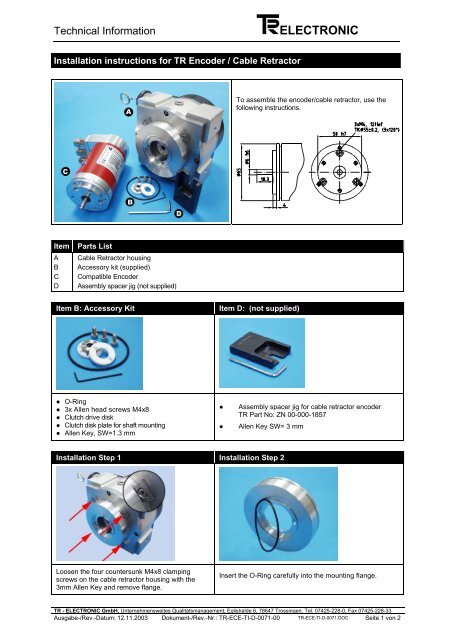
Technical InformationELEC<strong>TR</strong>ONICInstallation instructions for <strong>TR</strong> Encoder / Cable RetractorTo assemble the encoder/cable retractor, use thefollowing instructions.ItemABCDParts ListCable Retractor housingAccessory kit (supplied)Compatible EncoderAssembly spacer jig (not supplied)Item B: Accessory KitItem D: (not supplied)● O-Ring● 3x Allen head screws M4x8● Clutch drive disk● Clutch disk plate for shaft mounting● Allen Key, SW=1.3 mm●●Assembly spacer jig for cable retractor encoder<strong>TR</strong> Part No: ZN 00-000-1857Allen Key SW= 3 mmInstallation Step 1 Installation Step 2Loosen the four countersunk M4x8 clampingscrews on the cable retractor housing with the3mm Allen Key and remove flange.Insert the O-Ring carefully into the mounting flange.<strong>TR</strong> - ELEC<strong>TR</strong>ONIC GmbH, Unternehmensweites Qualitätsmanagement, Eglishalde 6, 78647 Trossingen, Tel. 07425-228-0, Fax 07425-228-33Ausgabe-/Rev.-Datum: 12.11.2003 Dokument-/Rev.-Nr.: <strong>TR</strong>-ECE-TI-D-0071-00 <strong>TR</strong>-ECE-TI-D-0071.DOC Seite 1 von 2
Technical InformationELEC<strong>TR</strong>ONICInstallation Step 3Postion the assembly spacer jig on the encoder: Clutch disk will be positioned at a distance of2.8mm + 0.1 (see picture)Fasten the two M2,5x5 grub screws to the encoder shaftwith the Allen Key.Remove assembly spacer.Installation Step 4Line up the O-ring side of the mounting flange with theEncoder and fasten the three M4x8 Allen head screws.Warning!Screws must be secured with Loctite 241 Cat.No 24112.Installation Step 5Insert the Clutch drive disk into the plate on the cableretractor unit.Position the encoder mounting flange (with clutch plate)against the O-Ring of the Cable RetractorWarning!Gently pull the Cable Retractor cable until the clutch drivedisk engages correctly and the encoder and CableRetractor flanges are flat against each other.Connect encoder for rotational direction required.Installation Step 6Fasten the four M4x8 Allen screws on the Cable Retractorclamping ring.Warning!Screws must be secured with Loctite 241 Cat.No 24112.<strong>TR</strong> - ELEC<strong>TR</strong>ONIC<strong>TR</strong>-ECE-TI-D-0071_NA.pdf 3 Jun 04