Minor Rebuild for All 37U, 37H and 37F Series Wheels - JOST ...
Minor Rebuild for All 37U, 37H and 37F Series Wheels - JOST ...
Minor Rebuild for All 37U, 37H and 37F Series Wheels - JOST ...

Create successful ePaper yourself
Turn your PDF publications into a flip-book with our unique Google optimized e-Paper software.
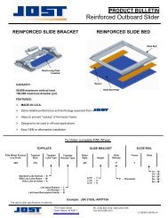
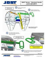
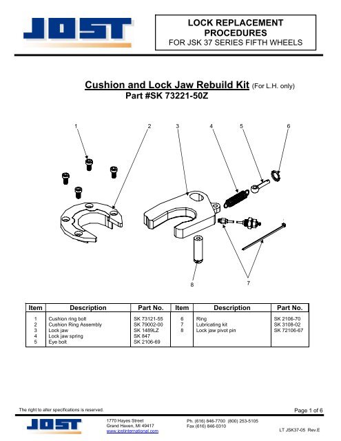
LOCK REPLACEMENTPROCEDURESFOR JSK 37 SERIES FIFTH WHEELSCushion <strong>and</strong> Lock Jaw <strong>Rebuild</strong> Kit (For L.H. only)Part #SK 73221-50Z1 2 3 4 5687Item Description Part No. Item Description Part No.12345Cushion ring boltCushion Ring AssemblyLock jawLock jaw springEye boltSK 73121-55SK 79002-00SK 1489LZSK 847SK 2106-69678RingLubricating kitLock jaw pivot pinSK 2106-70SK 3108-02SK 72106-67The right to alter specifications is reserved.Page 1 of 61770 Hayes StreetGr<strong>and</strong> Haven, MI 49417www.jostinternational.comPh. (616) 846-7700 (800) 253-5105Fax (616) 846-0310LT JSK37-05 Rev.E
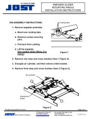
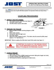
DISASSEMBLY1. CLOSE THE LOCKING MECHANISM.Pull the release h<strong>and</strong>le out <strong>and</strong> swingthe lock jaw into the closed position(see figure 1a).Now let the release h<strong>and</strong>le slideslowly to the closed position(see figure 1b).FIGURE 1aFIGURE 1b2. REMOVE DOUBLE COIL SPRING.Using a suitable tool remove the springfrom casting lug first (see figure 2).FIGURE 23. OPEN THE LOCKING MECHANISM.Slide the release h<strong>and</strong>le to theopened position (see figure 3).FIGURE 3The right to alter specifications is reserved.Page 2 of 61770 Hayes StreetGr<strong>and</strong> Haven, MI 49417www.jostinternational.comPh. (616) 846-7700 (800) 253-5105Fax (616) 846-0310LT JSK37-05 Rev.E
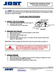
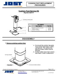
4. REMOVE THE CIRCLE RING.DISASSEMBLY con’tRemove the circle ring securing the lock jaw spring (see figure 4a) <strong>and</strong> allowextension spring to relax (see figure 4b).FIGURE 4aFIGURE 4b5. REMOVE THE CUSHION RING AND RETAINER.Remove the (4) cushion ring bolts using a 5/16” <strong>All</strong>en wrench (see figure 5a).Then, pry out the cushion ring retainer from the casting <strong>and</strong> remove the cushionring (see figure 5b).FIGURE 5aFIGURE 5b6. REMOVE THE LOCK JAW PIVOT PIN.Thread one of the cushion ring bolts into the lock jaw pivot pin (see figure 6a) <strong>and</strong>lift the pin from the casting (see figure 6b).FIGURE 6aFIGURE 6bThe right to alter specifications is reserved.Page 3 of 61770 Hayes StreetGr<strong>and</strong> Haven, MI 49417www.jostinternational.comPh. (616) 846-7700 (800) 253-5105Fax (616) 846-0310LT JSK37-05 Rev.E
DISASSEMBLY con’t7. REMOVE THE LOCK JAW.FIGURE 7Remove the lock jaw by reaching underthe top plate <strong>and</strong> sliding the lock out ofthe casting (see figure 7).8. REMOVE THE LUBRICATION LINE.FIGURE 8Remove the lubrication line from thelock jaw.RE-ASSEMBLY1. INSTALL THE LUBRICATION LINE.FIGURE 9Re-attach the lubrication line to the lock jaw.2. INSTALL THE LOCK JAW.FIGURE 10Be sure to install the lock jaw in the sameorientation it was removed (see figure 10).3. INSTALL THE CIRCLE RING.FIGURE 11Place the end of the eye bolt throughthe casting rib <strong>and</strong> secure with thecircle ring (see figure 11).The right to alter specifications is reserved.1770 Hayes StreetGr<strong>and</strong> Haven, MI 49417www.jostinternational.comPh. (616) 846-7700 (800) 253-5105Fax (616) 846-0310Page 4 of 6LT JSK37-05 Rev.E
RE-ASSEMBLY con’t4. INSTALL THE LOCK JAW PIVOT PIN.FIGURE 12Lubricate the lock jaw pivot pin <strong>and</strong>secure the lock jaw by inserting it intothe casting through the slot in the lockjaw (see figure 12).5. INSTALL THE CUSHION RING AND RETAINER.Carefully line up the bolt holes (see figure 13a), <strong>and</strong> then install (4) new cushion ringbolts. Tighten <strong>and</strong> torque bolts to 45 ft-lbs (see figure 13b).45 FT/LBSFIGURE 13aFIGURE 13b6. CLOSE THE LOCKING MECHANISM.Pull the release h<strong>and</strong>le out <strong>and</strong> swingthe lock jaw into the closed position(see figure 14a).Now slide the release h<strong>and</strong>leinto the closed position(see figure 14b).FIGURE 14aFIGURE 14b7. ATTACH DOUBLE COIL SPRING.Using a suitable tool attach the spring as shown (see figure 2).The right to alter specifications is reserved.1770 Hayes StreetGr<strong>and</strong> Haven, MI 49417www.jostinternational.comPh. (616) 846-7700 (800) 253-5105Fax (616) 846-0310Page 5 of 6LT JSK37-05 Rev.E
RE-ASSEMBLY con’t8. CHECK ADJUSTMENT - Lock <strong>and</strong> unlock several times using a lock tester.A. THE LOCK IS PROPERLY ADJUSTED IF:The wheel locks <strong>and</strong> unlocks easily eachtime <strong>and</strong> the lock tester rotates freely.B. THE LOCK IS TOO LOOSE IF: You feel <strong>for</strong>eaftplay when pulling <strong>and</strong> pushing on thelock tester h<strong>and</strong>le (see figure 4)C. THE LOCK IS TOO TIGHT IF: The lock testerdoes not rotate freely when attempting torotate it in the lock. (See figure 5)Look <strong>for</strong> movementof kingpin in lockDisengage HookRotate LockTesterPull & PushH<strong>and</strong>leFIGURE 4FIGURE 59. CORRECT IMPROPER ADJUSTMENTA. IF IT IS TOO TIGHT: loosen the jam nut, turn theadjustment screw clockwise one full turn <strong>and</strong> resetthe jam nut. Then, lock <strong>and</strong> unlock several times,repeat if necessary.TURN ADJUSTMENT SCREWCLOCKWISE COUNTER CLOCKWISEB. IF IT IS TOO LOOSE: loosen the jam nut, turn theadjustment screw counterclockwise one full turn<strong>and</strong> reset the jam nut. Then, lock <strong>and</strong> unlockseveral times, repeat if necessary.IF TOO TIGHTIF TOO LOOSEThe right to alter specifications is reserved.1770 Hayes StreetGr<strong>and</strong> Haven, MI 49417www.jostinternational.comPh. (616) 846-7700 (800) 253-5105Fax (616) 846-0310Page 6 of 6LT JSK37-05 Rev.E